Volume 2010, Article ID 528378,13pages doi:10.1155/2010/528378
Research Article
Computationally Efficient Power Allocation
Algorithm in Multicarrier-Based Cognitive Radio Networks:
OFDM and FBMC Systems
Musbah Shaat and Faouzi Bader
Centre Tecnol`ogic de Telecomunicacions de Catalunya (CTTC), Parc Mediterrani de la Tecnolog´ıa (PMT), Avenida Carl Friedrich Gauss 7, Castelldefels, 08860 Barcelona, Spain
Correspondence should be addressed to Musbah Shaat,[email protected]
Received 4 June 2009; Revised 19 October 2009; Accepted 23 December 2009
Academic Editor: Behrouz Farhang-Boroujeny
Copyright © 2010 M. Shaat and F. Bader. This is an open access article distributed under the Creative Commons Attribution License, which permits unrestricted use, distribution, and reproduction in any medium, provided the original work is properly cited.
Cognitive Radio (CR) systems have been proposed to increase the spectrum utilization by opportunistically access the unused spectrum. Multicarrier communication systems are promising candidates for CR systems. Due to its high spectral efficiency, filter bank multicarrier (FBMC) can be considered as an alternative to conventional orthogonal frequency division multiplexing (OFDM) for transmission over the CR networks. This paper addresses the problem of resource allocation in multicarrier-based CR networks. The objective is to maximize the downlink capacity of the network under both total power and interference introduced to the primary users (PUs) constraints. The optimal solution has high computational complexity which makes it unsuitable for practical applications and hence a low complexity suboptimal solution is proposed. The proposed algorithm utilizes the spectrum holes in PUs bands as well as active PU bands. The performance of the proposed algorithm is investigated for OFDM and FBMC based CR systems. Simulation results illustrate that the proposed resource allocation algorithm with low computational complexity achieves near optimal performance and proves the efficiency of using FBMC in CR context.
1. Introduction
Federal Communications Commission (FCC) has reported that many licensed frequency bands are severely under-utilized in both time and spatial domain [1]. Assigning frequency bands to specific users or service providers exclusively does not guarantee that the bands are being used efficiently all the time. Cognitive radio (CR) [2–4], which is an intelligent wireless communication system capable of learning from its radio environment and dynamically adjust-ing its transmission characteristics accordadjust-ingly, is considered to be one of the possible solutions to solve the spectrum
efficiency problem. By CR, a group of unlicensed users
(referred to as secondary users (SUs)) can use the licensed frequency channels (spectrum holes) without causing a harmful interference to the licensed users (referred to as primary users (PUs)) and thus implement efficient reuse of the licensed channels.
Multicarrier communication systems have been sug-gested as a candidate for CR systems due to its flexibility to allocate resources between the different SUs. As the SU and PU bands may exist side by side and their access
technologies may be different, the mutual interference
implementation has to be imposed among the network nodes [6].
The filter bank multicarrier system (FBMC) does not require any CP extension and can overcome the spectral leak-age problem by minimizing the sidelobes of each subcarrier and therefore lead to high efficiency (in terms of spectrum and interference) [6,7]. Moreover, efficient use of filter banks for spectrum sensing when compared with the FFT-based preiodogram and the Thomson’s multitaper (MT) spectrum sensing methods have been recently discussed in [6,8].
The problem of resource allocation for conventional (noncognitive) multiuser multicarrier systems has been widely studied [9–12]. The maximum aggregated data rate in downlink can be obtained by assigning each subcarrier to the user with the highest signal-to-noise ratio (SNR) and then the optimal power allocation that maximizes the channel capacity is waterfilling on the subcarriers with a given total power constraint [9]. In cognitive radio systems, two types of users (SU and PU) and the mutual interference between them should be considered. The use of the power allocation based on conventional waterfilling algorithm is not always efficient. An additional constraint should be introduced due to the interference caused by the sidelobes in different subcarriers. The transmit power of each subcarrier should be adjusted according to the channel status and the location of the subcarrier with respect to the PU spectrum.
Wang et al. in [13] proposed an iterative partitioned single user waterfilling algorithm. The algorithm aims to maximize the capacity of the CR system under the total power constraint with the consideration of the per subcarrier power constraint caused by the PUs interference limit. The per subcarrier power constraint is evaluated based on the pathloss factor between the CR transmitter and the PU protection area. The mutual interference between the SU and PU was not considered. In [14, 15], the authors proposed an optimal and two suboptimal power loading schemes using the Lagrange formulation. These loading schemes maximize the downlink transmission capacity of the CR system while keeping the interference induced to only one PU below a prespecified interference threshold without the consideration of the total power constraint. In [16], an algorithm called RC algorithm was presented for multiuser resource allocation in OFDM-based CR systems. This algorithm uses a greedy approach for subcarrier and power allocations by successively assigning bits, one at a time, based on minimum SU power and minimum interference to PUs. The algorithm has a high computational complexity and a limited performance in comparison with the optimal solution. In [17], a low complexity suboptimal solution is proposed. The algorithm initially assumes that the maximum power that can be allocated to each subcarrier is equal to the power found by the conventional waterfilling and then modifies these values by applying a power reduction algorithm in order to satisfy the interference constraints. Experimental results like [18] emphasize the need of low interference constraints where this algorithm has a limited performance. Moreover, the nontransmission of the data over the subcarriers below the waterfilling level or the deactivated subcarriers due to the power reduction algorithm
Secondary user (SU1)
(SU2)
(SU3)
(SU4)
Primary user (PU1)
(PU2)
(PU3)
(PU4)
Primary system base
station CR base station(CBS)
Figure1: Cognitive Radio Network.
decreases the overall capacity of the CR system. In [19], we give some preliminary research results for resource allocation in OFDM-based CR systems. This preliminary work consid-ers a simple model with one PU. The performance of the algorithm was not compared with neither the optimal nor the existed suboptimal algorithms.
In this paper, considering more realistic scenario with several primary user interference constraints, a computation-ally efficient resource allocation algorithm in multicarrier-based CR systems is proposed. The proposed algorithm maximizes the downlink capacity of the CR system under both total power and interference induced to the PUs constraints. The CR system can use the nonactive and active
PU bands as long as the total power and the different
interference constraints are satisfied. The simulation results demonstrate that the proposed solution is very close to the optimal solution with a good reduction in the computational complexity. Moreover, the proposed algorithm outperforms the previously presented algorithms in the literature. The efficiency of using FBMC in CR systems is investigated and compared to OFDM-based CR systems. The rest of this paper is organized as follows. Section 2 gives the system model whileSection 3formulates the problem. The proposed algo-rithm is presented inSection 4. Selected numerical results are presented inSection 5. Finally,Section 6concludes the paper.
2. System Model
B1 B2 BL
Active PU1band
Non-active band
Active PU2band
Active PULband
Frequency
1 2 · · · Δf N
. . .
. . .
Figure2: Frequency distribution of the active and nonactive primary bands.
subcarriers each having aΔf bandwidth. The side by side frequency distribution of the PUs and SUs will be assumed (see Figure 2). The frequency bands B1,B2,. . .,BL have been occupied by the PUs (active PU bands) while the other bands represent the nonactive PU bands. Its assumed that the CR system can use the nonactive and active PU bands provided that the total interference introduced to thelthPU band does
not exceedIl
thwhereIthl =Tthl Bldenotes that the maximum
interference power that can be tolerated by thePUlandTl th
is the interference temperature limit forPUl.
The interference introduced by theith subcarrier to lth
PU, Il
i(di,Pi), is the integration of the power spectrum
density (PSD),Φi, of theithsubcarrier across thelthPU band, Bl, and can be expressed as [5]
Iil(di,Pi)=
di+Bl/2
di−Bl/2
gil
2
Φi
fdf =PiΩli, (1)
where Pi is the total transmit power emitted by the ith
subcarrier and di is the spectral distance between the ith
subcarrier and thelthPU band.gl
i denotes the channel gain
between the ith subcarrier and the lth PU. Ωl
i denotes the
interference factor of theithsubcarrier.
The interference power introduced by thelth PU signal
into the band of theithsubcarrier is [5]
Jl i
di,PPUl
=
di+Δf /2
di−Δf /2
yl
i 2
ψlejωdω, (2)
whereψl(ejω) is the power spectrum density of thePUlsignal
and yil is the channel gain between theith subcarrier and lthPU signal. The PSD expression,Φ
i, depends on the used
multicarrier technique. The OFDM and FBMC PSDs are described in the following subsections.
2.1. OFDM System and Its PSD. The OFDM symbol is formed by taking the inverse discrete Fourier transform (IDFT) to a set of complex input symbols{Xk}and adding a cyclic prefix. This can be written mathematically as
x(n)= k
w∈Z
Xk,wgT(n−wT)ej2π(n−wT−C)k/N,
(3)
where{k}is the set of data subcarrier indices and is a subset of the set{0, 1,. . .,N−1},Nis the IDFT size,Cis the length of the cyclic prefix in number of samples, andT = C+N
is the length of the OFDM symbol in number of samples.
gT denotes the pulse shape, whilewdenotes thewthOFDM
symbol.
Following the derivation of the PSD for general baseband signal given in [20], it can be shown that the OFDM PSD is
ΦOFDM
f=σx2 T
k
GT f − k N
2, (4)
where GT(f) is the Fourier transform ofgT(n), and σ2 x is
the variance of the zero mean (symmetrical constellation) and uncorrelated input symbols. The assumption of the uncorrelated input symbols can be justified because of coding and interleaving in practical symbols [21].
gT(n) can be chosen as
gT(n)=
⎧ ⎨ ⎩
1, n=0, 1,. . .,T−1,
0, otherwise, (5)
and hence its Fourier transform is
GT
f2=T+ 2
T−1
r=1
(T−r) cos2π f r. (6)
2.2. FBMC System and Its PSD. Each subcarrier in FBMC
system is modulated with a staggered QAM (offset QAM)
[22]. The basic idea is to transmit real-valued symbols instead of transmitting complex-valued ones. Due to this time staggering of the in-phase and quadrature components of the symbols, orthogonality is achieved between adjacent subcarriers. The modulator and the demodulator are imple-mented using the synthesis and analysis filter banks. The filters in the synthesis and analysis filter bank are obtained by frequency shifts of a single prototype filter.Figure 3depicts the structure of the synthesis and analysis filter bank at the transmitter and receiver in FBMC-based multicarrier systems.
The FBMC, also called OQAM/OFDM, signal can be written mathematically as [23]
x(n)= k
w∈Z
ak,wh(n−wτo)ej2π(k/N)nejφk,w,
(7)
Input
symbols Channel
Re
jIm
jIm
Re 2
2
2
2
2
2
jIm
Re
Z−1
Z−1
Z−1
OQAM modulation
IFFT
H0
H1
HN−1
Z−1
Z−(N−1)
P/S S/P
Polyphase filtering
··· ··· ···
··· ···
(a)
Channel S/P
H0
H1
HN−1
Z−1
Z−(N−1)
FFT
2
2
Z−1
2
2
Re Z−1
Z−1 jIm
jIm Z−1
Z−1 2 Re
jIm Z−1
2 Re
P/S
Output
Polyphase
filtering OQAM modulation
··· ···
··· ··· ···
(b)
Figure3: FBMC system’s transmitter and receiver.
σ2
x. Hence, the FBMC symbols have a zero mean and finite
varianceσ2
r =σx2/2. The PSD of the FBMC can be expressed
by [23]
ΦFBMC=σ 2 r τ◦
k
H f − k N
2, (8)
where H(f) is the frequency response of the prototype filter with coefficients h[n] with n = 0,. . .,W − 1,
where W = KN and K is the length of each polyphase
components (overlapping factor) while N is the number
of the subcarriers. Assuming that the prototype coefficients
have even symmetry around the (KN/2)thcoefficient, and the first coefficient is zero [21], we get
H
f=h
W
2
+ 2
W/2−1
r=1
h W
2
−r
cos2π f r. (9)
To make a parallel between OFDM and FBMC, we place ourselves in the situation where both systems transmit the same quantity of information. This is the case if they have the same number of subcarriersNtogether with duration of
τosamples for FBMC real data andT=2τofor the complex QAM ones [21,23].
−0.2 0 0.2 0.4 0.6 0.8 1 1.2
4 5 6 7 8 9 10 11 12
A
m
plitude
Filter bank
OFDM
Sub-channel
Figure4: Single subcarrier PSDs of the OFDM and FBMC systems.
the individual subcarriers. Using the PHYDYAS prototype filter [24],Figure 4plots a single subcarrier power spectral densities of the OFDM and FBMC systems. It can be noted that the FBMC system has very small side lobes in comparison with that of the OFDM system. Note that in order to solve the large sidelobes problem in OFDM system, many methods have already been employed, such as the insertion of guard subcarriers [25] or cancelation subcarriers [26], windowing (in time domain) [27,28], and filtering before transmitting [29]. It is known that the guard subcarriers decrease the spectral efficiency, while windowing reduces the delay spread tolerance and filtering is more complex and introduces distortion in the desired signals [30].
3. Problem Formulation
The transmission rate of the ith subcarrier, Ri, with the
transmit power Pi can be evaluated using the Shannon
capacity formula and is given by
Ri(Pi,hi)=Δflog2
1 +Pi|hi|
2
σi2
, (10)
wherehiis the subcarrier fading gain from the CBS to the user.σ2
i =σAWGN2 +
L
l=1JilwhereσAWGN2 is the mean variance
of the additive white Gaussian noise (AWGN) andJl i is the
interference introduced by the lth PUs band into the ith
subcarrier. The interference from PUs to theith subcarrier
is assumed to be the superposition of large number of independent components, that is, Ll=1Jil. Hence, we can
model the interference as AWGN. This assumption may not be valid for low number of PU bands but can be considered as a good approximation for large number of PU bands. The same model can be found in [6,15,17]. Remark that the nature of the PUs interference on SUs band is the same
on both OFDM and FBMC systems. The difference is only
in the SUs interference to the PU bands, which is in that case FBMC has significantly lower interference, because of its significantly smaller sidelobes as compared to those of OFDM.
Assuming that each subcarrier band is narrow, subcar-riers can be approximated as channel with flat fading gains
[31,32]. It will be assumed that the channel changes slowly so that the channel gains will be constant during transmission. The total achievable rate for OFDM and FBMC systems is evaluated by summing the transmission rate across the different subcarriers [7, 33]. All the instantaneous fading gains are assumed perfectly known at the CR system and there is no intercarrier interference (ICI). Let vi,m to be a subcarrier allocation indicator, that is,vi,m = 1 if and only if the subcarrier is allocated to themth user. It is assumed
that each subcarrier can be used for transmission to at most one user at any given time. Our objective is to maximize the total capacity of the CR system subject to the instantaneous interference introduced to the PUs and total transmit power constraints. Therefore, the optimization problem can be formulated as follows:
P1 : max
Pi,m M
m=1 N
i=1
υi,mRi,mPi,m,hi,m (11)
subject to
υi,m∈ {0, 1}, ∀i,m, (12)
M
m=1
υi,m≤1, ∀i, (13)
M
m=1 N
i=1
υi,mPi,m≤PT, (14)
Pi,m≥0, ∀i∈ {1, 2,. . .,N}, (15)
M
m=1 N
i=1
υi,mPi,mΩli≤Ithl , ∀l∈ {1, 2,. . .,L}, (16)
where N denotes the total number of subcarriers, M is
the number of users,Ithl denotes the interference threshold
prescribed by the lth PU, and PT is the total SUs power
budget.Lis the number of the active PU bands. Inequality (13) ensures that any given subcarrier can be allocated to at most one user.
The optimization problem P1 is a combinatorial opti-mization problem and its complexity grows exponentially with the input size. In order to reduce the computational complexity, the problem is solved in two steps by many of the suboptimal algorithms [9–12]. In the first step, the subcarriers are assigned to the users and then the power is allocated for these subcarriers in the second step. Once the subcarriers are allocated to the users, the multiuser system can be viewed virtually as a single user multicarrier system. As proved in [9], the maximum data rate in downlink can be obtained if the subcarriers are assigned to the user who has the best channel gain for that subcarrier as described in
Algorithm 1.
can be determined from the subcarrier allocation step as follows:
hi= M
m=1
υi,mhi,m. (17)
Therefore, problem P1 in (11) can be reformulated as follows:
P2 : max
Pi N
i=1
log2
1 +Pi|hi|
2 σ2 i (18) subject to N
i=1
PiΩli≤Ithl ∀l∈ {1, 2,. . .,L}, (19)
N
i=1
Pi≤PT, (20)
Pi≥0 ∀i∈ {1, 2,. . .,N}. (21)
The problem P2 is a convex optimization problem. The
Lagrangian can be written as [17]
G= − N
i=1
log2
1 +P ∗
i |hi|2 σ2 i + L
l=1 αl
⎛ ⎝N
i=1
Pi∗Ωli−Ithl
⎞ ⎠
+β
⎛ ⎝N
i=1 P∗i −PT
⎞ ⎠−N
i=1 Pi∗μi,
(22)
where αl,l ∈ {1, 2,. . .,L},μi,i ∈ {1, 2,. . .,N}, and βare the Lagrange multipliers. The Karush-Kuhn-Tucker (KKT) conditions can be written as follows:
Pi∗≥0, ∀i∈ {1, 2,. . .,N},
αl≥0, ∀l∈ {1, 2,. . .,L},
β≥0,
μi≥0, ∀i∈ {1, 2,. . .,N},
αl
⎛ ⎝N
i=1
Pi∗Ωli−Ithl
⎞
⎠=0, ∀l∈ {1, 2,. . .,L},
β
⎛ ⎝N
i=1 Pi∗−PT
⎞ ⎠=0,
μiP∗i =0, ∀i∈ {1, 2,. . .,N},
∂G ∂Pi∗
= −1 σi2/|hi|2+P∗i
+
L
l=1 αlΩl
i+β−μi=0,
(23)
and also the solution should satisfy the total power and interference constraints given by (20) and (19). Rearranging the last condition in (23) we get
P∗i =
1 L
l=1αlΩli+β−μi − σi2
|hi|2. (24)
Initialization:
Setυi,m=0 ∀i,m
Subcarrier Allocation:
fori=1 toN do
m∗=argmax
m {
hi,m};υi,m∗=1
end for
Algorithm1: Subcarriers to user allocation.
SincePi∗≥0, we get
σi2 |hi|2 ≤
1 L
l=1αlΩli+β−μi
. (25)
Ifσi2/|hi|2<1/(
L
l=1αlΩi+β), thenμi=0 and hence
Pi∗=
1 L
l=1αlΩli+β − σi2
|hi|2. (26)
Moreover, ifσi2/|hi|2>1/(
L
l=1αlΩli+β), from (24) we get
1 L
l=1αlΩli+β−μi ≥ σi2
|hi|2 ≥
1 L
l=1αlΩli+β
, (27)
and sinceμiP∗i =0 andμi≥0, we get thatPi∗=0.
Therefore, the optimal solution can be written as follows:
Pi∗=
⎧ ⎪ ⎪ ⎪ ⎪ ⎨ ⎪ ⎪ ⎪ ⎪ ⎩ 1 L
l=1αlΩli+β − σi2
|hi|2 if σi2 |hi|2 <
1 L
l=1αlΩli+β
,
0 if σ
2 i |hi|2 ≥
1 L
l=1αlΩli+β
,
(28)
or more simply, (28) can be written as the follows:
Pi∗=
1 L
l=1αlΩli+β − σi2
|hi|2
+
, (29)
where [x]+ = max(0,x). Solving for L + 1 Lagrangian multipliers is computational complex. These multipliers can be found numerically using ellipsoid or interior point method with a complexityO(N3) [17,34]. In what follows
we will propose a low complexity algorithm that achieves near optimal performance.
4. Proposed Algorithm
As described in [5, 17], most of the interference introduced to the PU bands is induced by the cognitive transmission in the subcarriers where the PU is active as well as the subcarriers that are directly adjacent to the PU bands. Considering this fact, it can be assumed that each subcarrier is belonging to the closest PU band and only introducing interference to it, then the optimization problemP2 can be reformulated as follows:
P3 : max
P i
N
i=1
log2
1 +P
i|hi|2 σ2 i (30) subject to
i∈Nl
PiΩli≤Ithl ∀l∈ {1, 2,. . .,L},
N
i=1
Pi ≤PT,
Pi≥0 ∀i∈ {1, 2,. . .,N},
(31)
whereNldenotes the set of the subcarriers belong to thelth
PU band. Using the same derivation leading to (29), we get
Pi=
1
αlΩli+β − σi2
|hi|2
+
, (32)
where αl and β are the non-negative dual variables
corresponding to the interference and power constraints respectively. The solution of the problem still has high computational complexity which encourages us to find a faster and efficient power allocation algorithm.
If the interference constraints are ignored inP3, the solu-tion of the problem will follow the well-known waterfilling interpretation [35]
P(PT) i =
λ− σi2 |hi|2
+
, (33)
whereλis the waterfilling level. On the other side, if the total power constraint is ignored, the Lagrangian of the problem can be written as [15]
G(Int)= − i∈Nl
log2
1 +P
(Int) i |hi|2
σ2 i
+αl(Int)
⎛
⎝
i∈Nl
Pi(Int)Ωli−Ithl
⎞ ⎠,
(34)
whereαlis the Lagrange multiplier. Equating∂G(Int)/∂Pi(Int)
to zero, we get
Pi(Int)=
⎡
⎣ 1
αl(Int)Ωli − σi2
|hi|2
⎤ ⎦
+
, (35)
where the value ofαl can be calculated by substituting (35) intoi∈NlP
(Int)
i Ωi=Ithl to get
αl(Int)=
|Nl| Ithl +
i∈Nl
Ωliσi2/|hi|2
. (36)
It is obvious that if the summation of the allocated power under only the interference constraints is lower than or equal the available total power budget, that is, N
i=1P (Int)
i ≤ PT, for all i ∈ {1, 2,. . .,N}, then (35)-(36)
will be the optimal solution for the optimization problemP3. In most of the cases, the total power budget is quite lower than this summation, and hence the Power Interference (PI) constrained algorithm, referred to as PI-Algorithm, is proposed to allocate the power under both total power and interference constraints.
In order to solve the optimization problem P3, we can start by assuming that the maximum power that can be allocated for a given subcarrierPMax
i is determined according
to the interference constraints only by using (35)-(36) for every set of subcarriers Nl, for all l ∈ {1, 2,. . .,L}. By such an assumption, we can guarantee that the interference introduced to PU bands will be under the prespecified
thresholds. Once the maximum powerPMax
i is determined,
the total power constraint is tested. If the total power constraint is satisfied, then the solution has been found and is equal to the maximum power that can be allocated to each subcarrier, that is,Pi =PiMax. Otherwise, the available power
budget should be distributed among the subcarriers giving that the power allocated to each subcarrier is lower than or equal to the maximum power that can be allocated to each subcarrierPMaxi , and hence the following problem should be
solved:
P4 : max
PW.F i
N
i=1
log2
1 +P
W.F i |hi|2
σ2 i (37) subject to N
i=1
PiW.F≤PT,
0≤PiW.F≤PiMax.
(38)
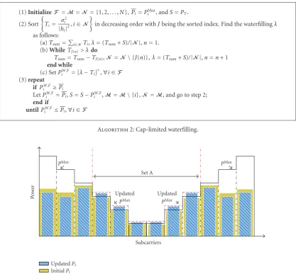
The problem P4 is called “cap-limited” waterfilling [36]. The problem can be solved efficiently using the concept of the conventional waterfilling. Given the initial waterfilling solution, the channels that violate the maximum powerPMax
i
are determined and upper bounded with PMax
i . The total
power budget is reduced by subtracting the power assigned so far. At the next step, the algorithm proceeds to successive waterfilling over the subcarriers that did not violate the
maximum power PMax
i in the last step. This procedure is
repeated until the allocated power PW.F
i does not violate
the maximum power PMax
i in any of the subcarriers in
the new iteration. The “cap-limited” waterfilling algorithm implementation is described inAlgorithm 2.
The solution PW.Fi of the problem P4 is satisfying the
total power constraint of the problem P3 with equality
which is not the case for the different interference constraints
Ithl . Since it is assumed that PW.Fi ≤ PiMax, some of the
powers allocated to subcarriers will not reach the maximum allowable values. This will make the interference introduced to the PU bands below the thresholdsIthl . In order to take
(1)InitializeF =M=N = {1, 2,. . .,N},Pi=PMax
i , andS=PT.
(2) Sort
Ti= σi2
|hi|2,i∈N
in decreasing order withJbeing the sorted index. Find the waterfillingλ
as follows:
(a)Tsum=i∈NTi,λ=(Tsum+S)/|N|,n=1.
(b)WhileTJ(n)> λdo
Tsum=Tsum−TJ(n),N =N\ {J(n)},λ=(Tsum+S)/|N|,n=n+ 1 end while
(c) SetPW.F
i =[λ−Ti]+,∀i∈F
(3)repeat
if PW.F
i ≥Pi LetPW.F
i =Pi,S=S−PiW.F,M=M\ {i},N =M, and go to step 2;
end if
untilPW.F
i ≤Pi,∀i∈F
Algorithm2: Cap-limited waterfilling.
InitialPi UpdatedPi
Po
w
er
Subcarriers
PMax
Set A
PMax
Updated
PMax
Updated
PMax
Figure5: An Example of the SUs allocated power using PI-Algorithm.
maximum power that can be allocated to each subcarrier
PMax
i should be updated depending on the left interference.
The left interference can be determined as follows:
Il
Left=Ithl −
i∈Nl PW.F
i Ωli. (39)
Assuming thatAl⊂Nlis the set of the subcarriers that reach its maximum, that is, PiW.F = PiMax, for all i ∈ Al, then, PMax
i , for alli∈Alcan be updated by applying (35)-(36) on
the subcarriers in the setAlwith the following interference constraints:
Ithl=ILeftl +
i∈Al
PiW.FΩli. (40)
After determining the updated values of PiMax, the “cap-limited” waterfilling is performed again to find the final solution Pi = PiW.F. Now, the solution Pi is satisfying
approximately the interference constraints with equality as well as guaranteing that the total power used is equal to
PT. A graphical description of thePI-Algorithmis given in
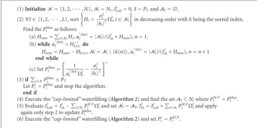
Figure 5while the implementation procedures are described inAlgorithm 3.
The computational complexity of Step 2 in the pro-posed PI-Algorithm (Algorithm 3) isLl=1O(|Nl|log|Nl|)≤ O(NlogN). Steps 4 and 6 of the algorithm execute the “cap-limited”waterfilling which has a complexity ofO(NlogN+
ηN), whereη≤Nis the number of the iterations. Step 5 has a complexity ofLl=1O(|Al|log|Al|) +O(L)≤O(NlogN) +
O(L). Therefore, The overall complexity of the algorithm is lower than O(NlogN+ηN) +O(L). The value of η is estimated via simulation to be lower than five, that is,η ∈
[0, 5]. Comparing to the computational complexity of the optimal solution,O(N3), the proposed algorithm has much
lower computational complexity specially when the number of the subcarriersNincreased.
5. Simulation Results
The simulations are performed under the scenario given in Figure 1. A multicarrier system of M = 3 cognitive
(1)InitializeN= {1, 2,· · ·,N},Nl=Nl,ILeftl =0,S=PTandAl= ∅.
(2)∀l∈ {1, 2,· · ·,L}, sort
Hi= σi2
|hi|2Ωli,i∈Nl
in decreasing order withkbeing the sorted index.
Find thePMax
i as follows: (a)Hsum=i∈NlHi,α
(Int)
l = |Nl|/(Ithl +Hsum),n=1.
(b)whileαl(Int)> H−1
k(n) do
Hsum=Hsum−Hk(n),Nl=Nl\ {k(n)},α (Int)
l = |Nl|/(Ithl +Hsum),n=n+ 1 end while
(c) SetPMax
i =
1 αl(Int)Ωli
− σi2
|hi|2 +
(3)if i∈NPiMax≤PT
LetPi =PiMaxand stop the algorithm.
end if
(4) Execute the“cap-limited”waterfilling (Algorithm 2) and find the setAl⊂NlwherePW.Fi =PMaxi . (5) EvaluateIl
Left=Ithl −
i∈NlP W.F
i Ωliand setNl=Al,Ithl =ILeftl +
i∈AlP W.F
i Ωliand apply again only step 2 to updatePMax
i .
(6) Execute the“cap-limited”waterfilling (Algorithm 2) and setPi =PiW.F.
Algorithm3: PI-Algorithm.
of Δf and PT are assumed to be 0.3125 MHz and 1 watt, respectively. AWGN of variance 10−6 is assumed. Without
loss of generality, the interference induced by PUs to the SUs band is assumed to be negligible. The channel gainsh
andg are outcomes of independent, identically distributed (i.i.d) Rayleigh distributed random variables (rv’s) with mean equal to “1” and assumed to be perfectly known at the (CBS). OFDM and FBMC-based cognitive radio systems are evaluated. The OFDM system is assumed to have a 6.67% of its symbol time as cyclic prefix (CP). For FBMC system, the prototype coefficients are assumed to be equal to PHYDYAS coefficients with overlapping factorK=4 and are defined by [24,37]
h[n]=1−1.94392 cos 2πn 128
+√2 cos 4πn 128
−0.470294 cos 6πn 128
, 0≤n≤127,
(41)
The optimal solution is implemented using the interior point method. We refer to the method proposed in [17] by Zhang algorithm. All the results have been averaged over 1000 iterations.
Two interference constraints belonging to two active PU bands, that is,L= 2, is assumed as given inFigure 6. Each active PU band is assumed to have six subcarriers where
|N1| = |N2| = 16. The achieved capacity using optimal, PI and Zhang algorithms for different interference constraints whereIth1 = Ith2 is plotted in Figure 7. It can be noted that
the proposed PI-algorithm approaches the optimal solution and outperforms Zhang algorithm. The effect of assuming that every subcarrier is belonging to the closest PU band and introducing interference to it only on the net interference introduced to the active PU bands is studied in Figures 8
and 9 for PU1 and PU2, respectively. It can be observed that the net interference induced using the PI-algorithm
is approximately satisfying the prespecified interference constraints which makes the assumption reasonable. Unlike the OFDM-based CR system, the interference induced by the FBMC-based system does not reach the pre-specified thresholds. This is because the FBMC-based CR system reaches to the maximum interference that can be introduced to the PU using the given power budget. Moreover, the interference induced by the proposed algorithm is less than that using Zhang algorithm. Returning toFigure 7, one can notice that the interference constraints afterIl
th =10mWatt
start to have no effect on the achieved capacity of the FBMC system. This indicates also that the FBMC system reaches the maximum interference for the given power budget. The small difference between the net interference values afterIthl =10m
Watt is due to averaging over different channel realizations. The achieved capacity of the different algorithms is plotted in
Figure 10with lower values of the interference constraints. It can be noticed that Zhang algorithm has a limited performance with low interference constraints because the algorithm turns off the subcarriers that have a noise level more than the initial waterfilling level and never uses these subcarriers again even if the new waterfilling level exceeds its noise level. Moreover, the algorithm deactivates some subcarriers, that is, transmit zero power, in order to ensure that the interference introduced to PU bands is below the prespecified thresholds. The lower the interference con-straints, the more the deactivated subcarriers which justifies the limited performance of this algorithm in low interference constraints.
To show the efficiency of transmitting over the active
PU bands as well as the nonactive bands, Figures 11 and
Non-active band
Active PU1band
Non-Active band
Active PU2band
Non-active band
B1 B2
N1 N2
N
1 2
Frequency
· · ·
Δf
Figure6: Frequency distribution with two active PU bands.
13 13.5 14 14.5 15 15.5 16 16.5 17
Optimal-OFDM PI-OFDM Zhang-OFDM
Optimal-FBMC PI-FBMC Zhang-FBMC
Ith1 (Watt)
Capacit
y
(bit/Hz/s)
2 4 6 8 10 12 14 16 18 20
×10−3
Figure7: Achieved capacity versus allowed interference threshold for OFDM- and FBMC-based CR systems—two active PU bands.
2 4 6 8 10 12 14 16 18 20
×10−3
2 4 6 8 10 12 14 16 18 20 22
×10−3
N
et
int
erfer
enc
e
(
I
1 th)
Threshold (Ith1)
PI-OFDM Zhang-OFDM
PI-FBMC Zhang-FBMC
Figure8: Total interference introduced to thePU1versus
interfer-ence threshold.
2 4 6 8 10 12 14 16 18 20
×10−3
2 4 6 8 10 12 14 16 18 20 22
×10−3
N
et
int
erfer
enc
e
(
I
2 th)
Threshold (I2 th)
PI-OFDM Zhang-OFDM
PI-FBMC Zhang-FBMC
Figure9: Total interference introduced to thePU2versus
interfer-ence threshold.
0.2 0.4 0.6 0.8 1 1.2 1.4 1.6 1.8 2
×10−5
0 2 4 6 8 10 12 14
Capacit
y
(bit/Hz/s)
Ith(Watt)
Optimal-OFDM PI-OFDM Zhang-OFDM
Optimal-FBMC PI-FBMC Zhang-FBMC
10 11 12 13 14 15 16 17
2 4 6 8 10 12 14 16 18 20
×10−3
Ith(Watt)
Capacit
y
(bit/Hz/s)
PI-OFDM PI-OFDM without PU band PI-FBMC PI-FBMC without PU band
Figure11: Achieved capacity versus allowed interference threshold with and without transmitting over active bands—two active PU bands.
0.2 0.4 0.6 0.8 1 1.2 1.4 1.6 1.8 2
×10−5
4 5 6 7 8 9 10 11 12 13 14
Capacit
y
(bit/Hz/s)
Ith(Watt)
PI-OFDM PI-OFDM without PU band PI-FBMC PI-FBMC without PU band
Figure12: Achieved capacity versus allowed interference threshold (low) with and without transmitting over active bands—two active PU bands.
more interference to the PUs than the other subcarriers, low power levels can be used in these bands with low interferences constraints. This justifies why the difference between the two systems decreases when the interference constraints decrease.
RC algorithm can be used if there is only one active
PU band, that is, L = 1. The RC algorithm allocates
the subcarriers and bits considering the relative importance between the power needed to transmit and the interference induced to the PU band. In order to compare the proposed PI-algorithm with RC algorithm, One active PU band with “12” subcarriers will be assumed as given inFigure 13. For
Non-active band
Active PU band
Non-active band
B
1 2 Δf N
Frequency
· · ·
Figure13: Frequency distribution with one active PU band.
11.5 12 12.5 13 13.5 14 14.5 15 15.5 16 16.5
2 4 6 8 10 12 14 16 18 20
×10−3
Ith(Watt)
Capacit
y
(bit/Hz/s)
Optimal-OFDM PI-OFDM Zhang-OFDM RC-OFDM
Optimal-FBMC PI-FBMC Zhang-FBMC RC-FBMC
Figure14: Achieved capacity versus allowed interference threshold for OFDM- and FBMC-based CR systems—one active PU band.
fair comparison, the same bit mapping used in [16] is
considered as follows:
bi= log2
1 +P
i|hi|2 σ2
i
!
, (42)
wherebidenotes the maximum number of bits in the symbol transmitted in theith subcarrier and ·denotes the floor
function. Figures 14 and15 show that the proposed algo-rithm performs better than the RC and Zhang algoalgo-rithms. In low interference constraints, RC algorithm performs better than Zhang algorithm because of the limited performance of Zhang algorithm with low interference constraints.
0.2 0.4 0.6 0.8 1 1.2 1.4 1.6 1.8 2
×10−5
0 2 4 6 8 10 12 14
Capacit
y
(bit/Hz/s)
Ith(Watt)
Optimal-OFDM PI-OFDM Zhang-OFDM RC-OFDM
Optimal-FBMC PI-FBMC Zhang-FBMC RC-FBMC
Figure15: Achieved capacity versus allowed interference threshold (low) for OFDM- and FBMC-based CR systems—one active PU band.
6. Conclusion
In this paper, a low complexity suboptimal resource allo-cation algorithm for multicarrier-based CR networks is presented. Our objective was to maximize the total downlink capacity of the CR network while respecting the available power budget and guaranteeing that no excessive interference is caused to the PUs. With a significant reduction in the computational complexity fromO(N3) toO(NlogN+ηN)+ O(L),η∈[0, 5], It is shown that the proposed PI-algorithm achieves a near optimal performance and outperforms the suboptimal algorithms proposed so far. It is found that the net total interference introduced to the PUs band is relatively not affected by assuming that each subcarrier is belonging to the closest PU band and only introducing interference to it. Its demonstrated also that capacity of the CR system uses the nonactive as well as the active bands is more than that only uses the nonactive bands. Simulation results prove that the FBMC-based CR systems
have more capacity than OFDM-based ones. FBMC offers
more spectral efficiency and introduces small interference to the PUs. The obtained results contribute in recommending the use of FBMC physical layer in the future cognitive radio systems. Developing a resource allocation algorithm that considers the fairness among different users as well as their quality of service (QoS) will be the guideline of our future research work towards better radio resource management.
Acknowledgment
This work was partially supported by the European ICT-2008-211887 project PHYDYAS.
References
[1] Federal Communication Commission, “Spectrum Policy Task Force,” Report of ET Docket 02-135, November 2002. [2] J. Mitola III, “Cognitive radio for flexible mobile multimedia
communications,” inProceedings of IEEE International Work-shop on Mobile Multimedia Communications (MoMuC ’99), pp. 3–10, San Diego, Calif, USA, November 1999.
[3] T. A. Weiss and F. K. Jondral, “Spectrum pooling: an innova-tive strategy for the enhancement of spectrum efficiency,”IEEE Communications Magazine, vol. 42, no. 3, pp. S8–S14, 2004. [4] S. Haykin, “Cognitive radio: brain-empowered wireless
com-munications,”IEEE Journal on Selected Areas in Communica-tions, vol. 23, no. 2, pp. 201–220, 2005.
[5] T. Weiss, J. Hillenbrand, A. Krohn, and F. K. Jondral, “Mutual interference in OFDM-based spectrum pooling systems,” in
Proceedings of the 59th IEEE Vehicular Technology Conference (VTC ’04), vol. 59, Milan, Italy, May 2004.
[6] B. Farhang-Boroujeny and R. Kempter, “Multicarrier commu-nication techniques for spectrum sensing and commucommu-nication in cognitive radios,”IEEE Communications Magazine, vol. 46, no. 4, pp. 80–85, 2008.
[7] H. Zhang, D. L. Ruyet, and M. Terre, “On spectral effi -ciency analysis between OFDM/OQAM and OFDM based CR networks,” in Proceedings of the IEEE Vehicular Technology Conference (VTC ’09), Barcelona, Spain, 2009.
[8] B. Farhang-Boroujeny, “Filter bank spectrum sensing for cognitive radios,”IEEE Transactions on Signal Processing, vol. 56, no. 5, pp. 1801–1811, 2008.
[9] J. Jang and K. B. Lee, “Transmit power adaptation for multiuser OFDM systems,”IEEE Journal on Selected Areas in Communications, vol. 21, no. 2, pp. 171–178, 2003.
[10] D. Kivanc, G. Li, and H. Liu, “Computationally efficient bandwidth allocation and power control for OFDMA,”IEEE Transactions on Wireless Communications, vol. 2, no. 6, pp. 1150–1158, 2003.
[11] Z. Shen, J. G. Andrews, and B. L. Evans, “Optimal power allocation in multiuser OFDM systems,” inProceedings of IEEE Global Telecommunications Conference (GLOBECOM ’03), vol. 1, pp. 337–341, San Francisco, Calif, USA, December 2003. [12] C. Y. Wong, R. S. Cheng, K. B. Letaief, and R. D. Murch,
“Multiuser OFDM with adaptive subcarrier, bit, and power allocation,”IEEE Journal on Selected Areas in Communications, vol. 17, no. 10, pp. 1747–1758, 1999.
[13] P. Wang, M. Zhao, L. Xiao, S. Zhou, and J. Wang, “Power allocation in OFDM-Based cognitive radio systems,” in
Proceedings of IEEE Global Telecommunications Conference (GLOBECOM ’07), pp. 4061–4065, 2007.
[14] G. Bansal, M. J. Hossain, and V. K. Bhargava, “Adaptive power loading for OFDM-based cognitive radio systems,” in Pro-ceedings of IEEE International Conference on Communications (ICC ’07), pp. 5137–5142, Glasgow, UK, 2007.
[15] G. Bansal, M. J. Hossain, and V. K. Bhargava, “Optimal and suboptimal power allocation schemes for OFDM-based cognitive radio systems,”IEEE Transactions on Wireless Com-munications, vol. 7, no. 11, pp. 4710–4718, 2008.
[16] T. Qin and C. Leung, “Fair adaptive resource allocation for multiuser OFDM cognitive radio systems,” in Proceedings of the 2nd International Conference on Communications and Networking in China (ChinaCom ’07), August 2007.
[18] G. Stuber, S. Almalfouh, and D. Sale, “Interference analysis of TV-band whitespace,”Proceedings of the IEEE, vol. 97, no. 4, pp. 741–754, 2009.
[19] M. Shaat and F. Bader, “Power allocation with interference constraint in multicarrier based cognitive radio systems,” in
Proceedings of the 7th International Workshop on Multi-Carrier Systems and Solutions (MCSS ’09), Herrsching, Germany, May 2009.
[20] J. G. Proakis and M. Salehi,Communication Systems Engineer-ing, Prentice-Hall, Upper Saddle River, NJ, USA, 2nd edition, 2002.
[21] L. G. Baltar, D. S. Waldhauser, and J. Nossek, “Out-of-band radiation in multicarrier systems: a comparison,” in
Proceedings of the International Workshop on Multi-Carrier Systems & Solutions (MC-SS ’07), pp. 107–116, Springer, May 2007.
[22] B. Hirosaki, “An orthogonally multiplexed QAM system using the discrete fourier transform,” IEEE Transactions on Communications Technology, vol. 29, no. 7, pp. 982–989, 1981. [23] A. Skrzypczak, P. Siohan, and J.-P. Javaudin, “Power spectral density and cubic metric for the OFDM/OQAM modulation,” in Proceedings of the 6th IEEE International Symposium on Signal Processing and Information Technology (ISSPIT ’06), Vancouver, Canada, August 2006.
[24] “PHYDYAS-Physical layer for dynamic spectrum access and cognitive radio,”http://www.ict-phydyas.org/.
[25] A. Jayalath and C. Tellambura, “Reducing the out-of-band radiation of OFDM using an extended guard interval,” in Proceedings of the 53rd Vehicular Technology Conference (VTC ’01), vol. 2, pp. 829–833, Rhodes, Greece, May 2001. [26] S. Brandes, I. Cosovic, and M. Schnell, “Reduction of
out-of-band radiation in OFDM systems by insertion of cancellation carriers,”IEEE Communications Letters, vol. 10, no. 6, pp. 420– 422, 2006.
[27] Y.-P. Lin and S.-M. Phoong, “Window designs for DFT-based multicarrier systems,”IEEE Transactions on Signal Processing, vol. 53, no. 3, pp. 1015–1024, 2005.
[28] H. A. Mahmoud and H. Arslan, “Sidelobe suppression in OFDM-based spectrum sharing systems using adaptive symbol transition,”IEEE Communications Letters, vol. 12, no. 2, pp. 133–134, 2008.
[29] A. Vahlin and N. Holte, “Optimal finite duration pulses for OFDM,”IEEE Transactions on Communications, vol. 44, no. 1, pp. 10–14, 1996.
[30] R. Xu and M. Chen, “Spectral leakage suppression of DFT-based OFDM via adjacent subcarriers correlative coding,” inProccedings of IEEE Global Telecommunications Conference (GLOBECOM ’08), pp. 3029–3033, December 2008.
[31] A. Amini, R. Kempter, L. Lin, and B. Farhang-Boroujeny, “Fil-ter bank multitone: a candidate for physical layer of cognitive radio,” inProceedings of the Software Defined Radio Technical Conference and Product Exhibition (SDR ’05), Orange County, Calif, USA, November 2005.
[32] A. Amini, R. Kempter, and B. Farhang-Boroujeny, “A compar-ison of alternative filterbank multicarrier methods in cognitive radios,” inProceedings of the Software Defined Radio Technical Conference and Product Exhibition (SDR ’06), Orlando, Fla, USA, November 2006.
[33] H. Zhang, D. Le Ruyet, and M. Terre, “Spectral efficiency comparison between OFDM/OQAM- and OFDM-based CR networks,”Wireless Communications and Mobile Computing, vol. 9, no. 11, pp. 1487–1501, 2009.
[34] S. Boyd and L. Vandenberghe, Convex Optimization, Cam-bridge University Press, CamCam-bridge, UK, 2004.
[35] A. Leke and J. Cioffi, “A maximum rate loading algorithm for discrete multitone modulation systems,” in Proceedings of the IEEE Global Telecommunications Conference (GLOBE-COM ’97), vol. 3, pp. 1514–1518, 1997.
[36] N. Papandreou and T. Antonakopoulos, “Bit and power allocation in constrained multicarrier systems: the single-user case,”EURASIP Journal on Advances in Signal Processing, vol. 2008, Article ID 643081, 14 pages, 2008.