© 2015, IRJET.NET- All Rights Reserved Page 1316
System Identification Using Neural Network Model for Speed Control of
DC Motor
Dinesh L. Mute
1, Khushal Chaudhari
2, Ramesh Khamari
3, Abhijit Singare
41,4
Asst. Prof, Electrical Engineering Department, DMIETR, Sawangi (Meghe),Wardha(MH), India
2Asst. Prof, Electrical Engineering Department, ADCET, Ashta, Sangli(MH), India
3
Student, Electrical Engineering Department, NIT Rourkela , Odisha, India
---***---Abstract -
This paper proposed identification by using Artificial Neural Networks (ANNs) model for speed control of DC Motor. The output waveform trajectory of the dc motor model can be made to follow a reference model with fine accuracy. The purpose is to achieve accurate identified model of DC motor. The identified neural network model is for designing controller for speed control of DC motor. Such neural networks are trained by Levenberg-Marquardt back-propagation algorithm. ANNs used in this paper are the standard three layers feed-forward neural network with sigmoid activation functions in the input and hidden layers while linear activation function is employed for the output layer.Key Words
: Artificial Neural Networks (ANNs), DC Motor, Identification.1. INTRODUCTION
The DC Motor is widely used for speed application because of this controlling the DC Motor at specified speed or desired speed is to be achieved. For speed control of DC Motor conventional constant gain feedback controller fails to maintain the performance of the system at acceptable levels under unknown dynamics. On the other hand, ANNs act as an effective tool to implement the model and adaptive control in a complicated non-linear system having expansive allocations. The adaptive learning algorithm is formed in such a way that the learning rate is as large as possible while maintaining the stability of the learning process. This simplifies the learning process in terms of computation time, which is main parameter in real-time implementation.
The organization of the paper is as follows: Section II represents the dynamic model of a DC Motor. In section III, the Neural Network basic is described. Section IV gives the Neural Network model representation of system. Section V contains the simulation results of Neural Network model identification. Finally section VII provides the conclusion.
2. DYNAMIC MODEL OF DC MOTOR
DC Motor is widely used in various applications such as in industries, rotation of limbs in robot etc. DC motors are most suitable for wide range speed control. In the case of motor, the input is electrical energy and the output is the mechanical energy, with an air gap torque of Te at a rotational speed of ωm .The field windings are used to
excite the field flux. The input is supplied in the form of armature current to the rotor via brush and commutator for the mechanical operation. Interaction of field flux and armature current in the rotor produces torque. When a motor is excited by a field current of if and an armature current of ia flows in the circuit and the motor produces a back emf and a torque to balance the load torque at a particular speed. The circuit diagram of DC Motor shown in figure 1.
Fig.1 Circuit Diagram of DC Motor
© 2015, IRJET.NET- All Rights Reserved Page 1317 Where,
= Rotor Speed (rad/sec)
= Terminal Voltage (v)
= Armature Current
= Load Torque (Nm)
= Rotor Inertia (Nm2)
= Torque & Back emf Constant (Nm/A)
= Viscous friction Coefficient (Nm)
= Armature Resistor (Ω)
= Armature Inductor (H)
3. NEURAL NETWORKS
The neural network consists of junctions which are connected with LINKS, also called processing blocks. For each and every junction a number is given, this number is called weight. The weights are the tools for the long distance information storing in the neural network, the learning process occurring with the appropriate changes of weights. These weights are changed so that the network input/output behavior is in consonance with the environment, which provide the input data. The calculation algorithm consists of two basic steps such as calculation of the output of the network, with inputs, weights and modification of weights with learning algorithm.
A single input neuron consists of a scalar input “p” multiplied by the scalar weight “w” to form “wp” which is feed to the summer along with bias “b” multiplied by “1”. The net input is “wp+b” and the output “a” is;
(3)
where,
f- Transfer function
W & b can be adjusted by learning rule.
Fig.2. Basic Neural Network
4. SYETEM IDENTIFICATION
It is to train a neural network to represent the forward dynamics of the plant. The estimation error between the plant output and the neural network output is used as the neural network training signal. In the control design stage, you use the neural network plant model to design (or train) the controller. For model reference control, the controller is a neural network that is trained to control a plant so that it follows a reference model. The neural network plant model is used to assist in the controller training. The schematic block diagram of system identification by using neural network model of DC motor is given in figure 3. The identified model of DC Motor is used for designing control architecture.
© 2015, IRJET.NET- All Rights Reserved Page 1318 (4)
where,
W = Speed of motor;
Va= voltage supplied;
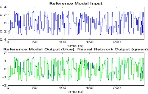
Reference Model of DC Motor:
(5)
The reference model shown in equation 5 is selected to achieve objective of the control system that is to drive the motor so that its speed, w(k), follows are specified trajectory, wm (k). This is done by allowing the dc motor to follow the output of a selected reference model throughout the trajectory.
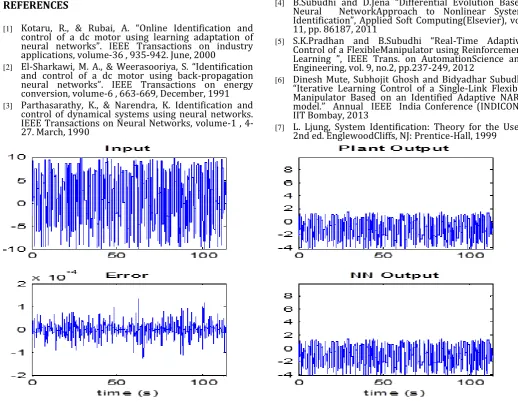
5. RESULT AND DISCUSSION
For Identification of Neural Network Model for DC Motor the input signal is selected as random reference block having the range -10 to +10. The input and plant output for above input signal is shown in figure 5 along with the identification Neural Network Model output and the error between the Plant output and the identified Neural Network Model. The parameter present in equation 4 is estimated from result of identification. The value of estimated parameter are as follows, k1=0.34366,
k2=-0.1534069, k3=-2.286928*10-3, k4=3.5193358*10-4, k5=0.2280595 and k6=-0.105184. Estimated Parameter is used to train neural network based control structure of MRAC. In table 1 shows the parameter value used for plant Identification.
Table 1.Plant Identification
Network architecture
Size of Hidden Layer 20
No. Delayed Plant Input 2
No. Delayed Plant Output 2
Sampling Interval(sec) 0.05
Training Data
Training Samples 10000
Maximum Plant Input 10
Minimum Plant Input -10
Maximum Interval Value (sec) 2
Minimum Interval Value (sec) 0.1
Maximum Plant Output 3.1
Minimum Plant output -3.1
Training Parameter
Training Epochs 300
Training Function Trainlm
Figure 5 shows the response of plant for applied reference model.
6. CONCLUSION
© 2015, IRJET.NET- All Rights Reserved Page 1319
REFERENCES
[1] Kotaru, R., & Rubai, A. “Online Identification and
control of a dc motor using learning adaptation of neural networks”. IEEE Transactions on industry applications, volume-36 , 935-942. June, 2000
[2] El-Sharkawi, M. A., & Weerasooriya, S. “Identification
and control of a dc motor using back-propagation neural networks”. IEEE Transactions on energy conversion, volume-6 , 663-669, December, 1991
[3] Parthasarathy, K., & Narendra, K. Identification and
control of dynamical systems using neural networks. IEEE Transactions on Neural Networks, volume-1 , 4-27. March, 1990
[4] B.Subudhi and D.Jena “Differential Evolution Based
Neural NetworkApproach to Nonlinear System Identification”, Applied Soft Computing(Elsevier), vol. 11, pp. 86187, 2011
[5] S.K.Pradhan and B.Subudhi “Real-Time Adaptive
Control of a FlexibleManipulator using Reinforcement Learning ”, IEEE Trans. on AutomationScience and Engineering, vol. 9, no.2, pp.237-249, 2012
[6] Dinesh Mute, Subhojit Ghosh and Bidyadhar Subudhi
“Iterative Learning Control of a Single-Link Flexible Manipulator Based on an Identified Adaptive NARX model.” Annual IEEE India Conference (INDICON), IIT Bombay, 2013
[7] L. Ljung, System Identification: Theory for the User,
2nd ed. EnglewoodCliffs, NJ: Prentice-Hall, 1999