R E S E A R C H
Open Access
Optimum low complexity filter bank for
generalized orthogonal frequency division
multiplexing
Mohammad Hadi Abbaszadeh
1, Babak H. Khalaj
2,3*and Afrooz Haghbin
1Abstract
Generalized frequency division multiplexing (GFDM) is one of the multicarrier modulation candidates proposed for the 5th generation of wireless networks. Among GFDM linear receivers, GFDM MMSE receiver achieves the best error performance for multipath fading channels at the cost of high numerical complexity. Hence, the combination of GFDM match filter (MF) receiver and double-side successive interference cancellation (DSIC) method is used instead. However, there is a significant gap between the error performance of GFDM MMSE and DSIC/MF receivers for the case of employing modern channel coding. Recently, we have proposed a new multicarrier scheme based on GFDM architecture called generalized orthogonal frequency division multiplexing (GOFDM). This study derives an optimized cyclic tree-structured perfect reconstruction-quadrature mirror filter (PR-QMF) bank for GOFDM transceiver and then introduces a novel method for implementation of the optimum filter bank in the frequency domain. Employing such a fast and optimum filter bank provides several advantages for GOFDM transceiver. GOFDM transmitter mitigates out-of-band spectrum leak to the level of that of GFDM. In addition, choosing an appropriate configuration of filter bank yields lower peak to average power ratio in transmit signal of GOFDM compared to that of OFDM. On the other hand, while GOFDM MMSE receiver has lower numerical complexity compared with GFDM DSIC/MF receiver, its coded bit error rate curve is close to that of GFDM MMSE receiver. The aforementioned advantages envision GOFDM as a competitive candidate to be employed in the physical layer of new wireless applications.
1 Introduction
Spectrum is a limited media for growing demand of radio communications, and hence, spectrum efficiency is one of the important parameters to be taken into ac-count for any modulation proposed as the air interface of the 5th generation (5G) wireless networks. Low com-putational complexity of the transceiver algorithm is an-other important parameter especially for use cases that require low battery consumption. OFDM has been widely used in wireless transmission due to its low com-putational complexity and good performance for multi-path channels [1, 2]. In order to provide the possibility of using a simple one-tap frequency domain equalizer
(FDE) at the receiver side of OFDM, cyclic prefix (CP) is generally added to OFDM symbols. Since CP length should, at least, be equal to the channel length, CP over-head ratio is high for large channel spreads. Moreover, OFDM suffers from high out-of-band spectrum leak [3] which forces many subcarriers to be left vacant in order to fit the OFDM spectrum in an emission spectrum mask. Therefore, OFDM achieves low spectral efficiency due to large guard time and guard band and thus could not be recommended as an appropriate choice for new wireless applications.
Among the alternative filtered multicarrier schemes [4, 5], general frequency division multiplexing (GFDM) is known as a versatile multicarrier modulation being able to address many of the requirements of new wireless applica-tions [6]. GFDM was first introduced in [7] and then has been widely investigated in the 5GNOW project [8, 9]. Three common linear receivers, i.e., zero-forcing (ZF), * Correspondence:[email protected]
2
Department of Electrical Engineering, Sharif University of Technology, Tehran, Iran
3School of Computer Science, Institute for Research in Fundamental Sciences
(IPM), Tehran, Iran
Full list of author information is available at the end of the article
matched filter (MF), and minimum mean square error (MMSE) receivers, are evaluated for the receiver side of GFDM. Among GFDM linear receivers, GFDM MMSE receiver yields the lowest error rate at the cost of the high-est complexity which makes it unusable for many applica-tions [10]. Therefore, matched filter (MF) receiver in combination with the double-side successive interference cancellation (DSIC) algorithm is used instead to provide a trade-off between computational complexity and bit error rate (BER) performance [11].
On the basis of GFDM architecture, we have recently in-troduced a generic cyclic filtered multicarrier scheme called extended-GFDM. Employing perfect reconstruction-quadrature mirror filter (PR-QMF) bank in the generic scheme yields generalized orthogonal frequency division multiplexing (GOFDM). GOFDM benefits from architec-tural advantages of GFDM including flexibility of the struc-ture, high spectral efficiency, and low latency. We have shown GOFDM MMSE outperforms GFDM ZF receiver in terms of error performance on the assumption of perfect synchronization. In addition, we have proved GOFDM MMSE receiver has a simple structure that consists of one-tap MMSE-FDE prior to PR-QMF receiver filter bank [12].
The first contribution of this paper is to propose an op-timized tree-structured PR-QMF bank in order to achieve low out-of-band (OOB) spectrum emission. Simulation re-sults show that employing proposed optimized PR-QMF bank in GOFDM structure results in OOB spectrum leak as low as that of GFDM transmitter. In addition, it is shown GFDM and GOFDM transmitters which employ an appropriate configuration of filter bank can improve peak to average power ratio (PAPR) compared with that of OFDM transmit signal. As the second contribution, a novel method for implementing the cyclic tree-structured filter bank in the frequency domain is introduced. Such implementation results in a lower computational com-plexity for GOFDM MMSE receiver compared with exist-ing implementation techniques proposed for GFDM DSIC/MF receiver under multipath fading channels. Fur-ther, it will be seen GOFDM MMSE receiver yields better error performance compared with OFDM for multipath fading channel where modern error control coding is pre-sented in the setup. In the similar conditions, GFDM en-counters complexity and error performance challenges for MMSE and DSIC/MF receivers, respectively. The remaining parts of the paper are organized as follows. In
Section 2, the extended-GFDM scheme is described. In Section 3, the first optimum low-complexity PR-QMF bank is derived and then the GOFDM transceiver block diagram based on such filter bank is introduced. Simula-tion results presented in SecSimula-tion 4 compare GOFDM and GFDM in terms of spectrum localization, computational complexity, error performance, and PAPR considering OFDM as a benchmark. The paper is concluded in Section 5.
2 Extended-GFDM scheme
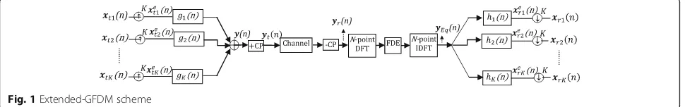
Figure 1 illustrates a general form of baseband multicar-rier modulation inspired from GFDM architecture; there-fore, it is called extended-GFDM scheme. At the transmitter side,xti(n) fori= 1 :KareKblocks ofM com-plex symbols generated by a QAM mapper. Up-sampling
xti(n) sequences by the factor of K generates xetið Þn se-quences ofN = MKsymbols whose symbols are given as
xetið Þ ¼n xti
sponses of transmitter and receiver filters with length less than or equal toN, we have
yðnÞ ¼XKi¼1xe tiðnÞ⊛
N
giðnÞ; ð2Þ
where⊛NdenotesN-point circular convolution.
Substitut-ing forxe
after extending toNsymbols through zero padding. Next,
inserting CP at the beginning of y(n) sequence generates
yt(n) sequence. At the receiver side, removing CP symbols
yieldsyr(n) sequence that may be expressed as the cyclic
convolution ofy(n) and the impulse response of multipath
fading channel. Employing FDE for yr(n) yields yEq(n),
where FDE needs anN-point DFT to transfer symbols to
frequency domain and anN-point IDFT to return them
back to time domain. Subsequently,xerið Þn fori= 1 :Kare
N-symbol sequences obtained as
xe
riðnÞ ¼yEqðnÞ⊛
N
hiðnÞ; ð4Þ
and then K-factor down-sampling operations yieldxri(n)
symbols as
xrið Þ ¼n xeriðnKÞforn¼0:M−1: ð5Þ
Since each gk(n) is a band-passed filter located at a
separate part of frequency domain, it can be considered as a subcarrier waveform. Assuming the sampling time to beTs, (3) shows that it will takeKTsseconds to
trans-mit one symbol of each subcarrier, and thus,Msymbols of each branch are carried within M time slots taking the total duration of MKTs seconds. Therefore, the
scheme isK-subcarrier andMtime slot modulation with block based output ofN = MK symbols. This result is in contrast with OFDM block (OFDM symbol) in which each subcarrier transmits one symbol during one time slot. The generic scheme gains some architectural ad-vantages that are described as follows:
Low latency: Since equalization is processed within one block, extended-GFDM has the advantage of low delay. In addition, cyclic filtering used in extended-GFDM scheme prevents to generate tail symbols, and thus, it has lower latency compared to linear filtered multicar-rier modulations.
Spectral efficiency: Extended-GFDM improves guard time overhead ratio compared with OFDM through sharing one CP among multiple time slots.
Flexible structure: In wireless cellular networks, small-M, large-Kconfigurations can be employed for downlink to provide multiple access and large-M, small-Kconfigurations may be used for uplink to mitigate PAPR.
Assumep(n) to be the impulse response of a prototype
filter. Substituting gið Þ ¼n p nð Þexp j2πði−K1Þn
In GFDM transmitter, data of i branch is filtered by use of a prototype filter and shifted in the frequency do-main through multiplying by exp j2πði−K1Þnfactor [13];
It is straightforward to show (6) and (7) are equal, and
therefore, employing gið Þ ¼n p nð Þexp j2πði−K1Þn
in the
extended-GFDM scheme leads to GFDM structure.
3 Filter bank design for GOFDM transceiver
GOFDM emerges through employing synthesis and ana-lysis PR-QMF banks at the transmitter and receiver sides of extended-GFDM scheme, respectively. Since GOFDM follows extended-GFDM structure, it takes the common architectural advantages of extended-GFDM described in previous section. In this section, we will address the design of PR-QMF bank to achieve low OOB spectrum leak and low order of computational complexity when employed in the GOFDM structure.
3.1 Background
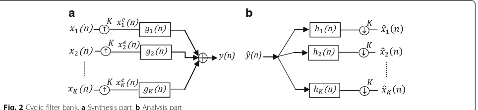
As seen in Fig. 2, PR-QMF bank consists of synthesis filter bank as multiplexing part and analysis filter bank as de-multiplexing part. Connecting the output of the synthesis part directly to the input of the analysis part will completely reconstruct the original inputs of the filter bank. Further-more, in PR-QMF bank, synthesis filters are matched to corresponding analysis filters [14]. In addition, perfect re-construction property is preserved even when the convolu-tions are performed circularly, and thus, PR-QMF banks can also be classified as cyclic orthogonal filter banks [15]. Two-band QMF banks are the simplest form of PR-QMF banks which are easily designed by using a prototype filter. Assumeh(n) to beL-tap prototype filter-derived such thatLis an even number and itsZtransform satisfies the following condition:
a
b
H zð ÞH z−1 þHð ÞH−z −z−1¼R zð Þ þRð Þ−z
¼Constant: ð8Þ
Perfect reconstruction property yields [16]
h1ð Þ ¼n h nð Þ; ð9Þ
and high-pass filters at the analysis part of 2-band
PR-QMF bank, respectively. Based on (8), considering R(z)
=H(z)H(z−1), the L-tap prototype filter of 2-band
PR-QMF bank can be obtained as the causal part of 2L-tap
half-band filterR(z). The half-band filterR(z) is a linear
phase FIR filter, and thus, we may use the
Parks-McClellan algorithm to derive R(z) so as to provide the
desired features for prototype filterH(z) [17].
Using a uniform tree structure of log2Klevels, 2-band
filter banks can be used for building K-band filter banks for the case where K is a power of two. By using the same prototype filter for generating 2-band filter banks in all levels of the tree, we may obtain the conventional tree-structured filter bank. However, 2-band filter banks used in different levels of a tree, even at each node of the same tree level, can be different for the most general case. Figure 3 shows 4-band tree-structured filter bank in which the filters with superscripts 1 and 2 belong to the first and second levels of the tree, respectively.
3.2 Optimized tree-structured PR-QMF bank
In this part, we introduce the tree-structured PR-QMF filter bank with localized frequency response sub-band filters. Our approach is the design of non-conventional tree struc-ture wherein different levels of tree have different 2-band filter banks but 2-band filter banks of the same level are similar. LetMbe the size of input sequences at the synthe-sis part of K-band tree-structured filter bank andhi(n) be the impulse response of the prototype filter employed to derive 2-band filter banks used inith level of the tree. The OOB spectrum leak depends on the behaviour of the filters within the passband and stopband. The optimization is thus aimed in designinghi(n) fori= 1 : log2Ksuch that the
fol-lowing optimization problem is satisfied
min Ei
subsequently, the optimizedK-band tree-structured filter
will be established when the 2-band filter banks used in
the ith level of tree are obtained by use of the derived
impulse responses gi
1ð Þn ;gi2ð Þn ;h1ið Þn and hi2ð Þn for i= 1 : log2K.
In our approach, first, the Parks-McClellan algorithm is used to design Ri(n) where the designing parameters are length, cut-off frequency and maximum ripple of the filter and then, hi(n) is derived as the causal part of Ri(n). We determine the designing parameters of Ri(n) so thatEiis minimized forhi(n). Noting that going from
each level to the successive higher one, the sequence size is duplicated, and hence, the size of input sequences at the ith level of tree is 2i−1M which is changed to 2iM after up-sampling by the order of two. In order to pre-serve the size of filtered sequences through cyclic filter-ing, the filters length has to be less than or equal to the size of filtered sequences, and thus, we have
Li≤2iM; ð14Þ
whereLiis the length ofhi(n). Since more spread in the time
domain permits designing of more localized sub-band filters in the frequency domain, the length of hi(n) is chosen to have the maximum possible value, i.e.,Li= 2iM. As a
conse-quence, the order of respective half-band filterRi(n) will be 2 × 2iM−1. In addition, cut-off frequency is set at the middle of frequency space (i.e., 0.5 for normalized frequency space).
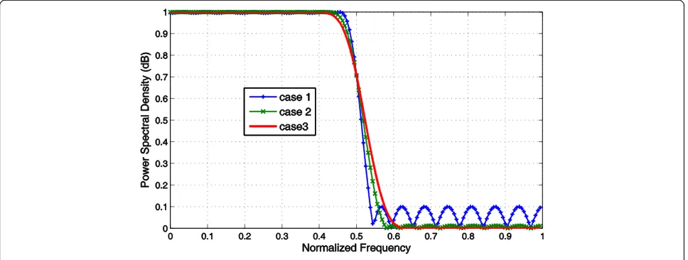
Ri(n) is then derived by use of Parks-McClellan algorithm and on the conditions that the order and cut-off frequency are fixed and the maximum ripple is numerically determined such that the achievedhi(n) minimizesEi. Figure4compares
frequency response of 32-tap optimum prototype filter (case 2) versus two non-optimum 32-tap prototype filters of cases 1 and 3 with larger and smaller maximum-ripples, respect-ively. The filters are derived as the causal parts of 64-tap half-band filters with the order and cut-off frequency equal to 61 and 0.5, respectively. For case 2, the maximum-ripple of respective half-band filter is numerically derived as 0.0121 while the maximum-ripples of cases 1 and 3 are chosen as 0.1 and 0.001, respectively. The values of Ei for cases 1, 2,
and 3 are 0.0944, 0.064, and 0.0712, respectively. The results
maximum-ripple compared to non-optimum prototype filters.
3.3 Low-complexity tree-structured PR-QMF bank
In this section, we propose a practical implementation algorithm in order to reduce the computational com-plexity of the optimum cyclic tree-structured filter bank. In order to reach this goal, the cyclic tree-structured fil-ter bank is implemented in the frequency domain using Discrete Fourier Transform (DFT) and Inverse DFT (IDFT), whereM-point DFT and IDFT are defined as:
X kð Þ ¼ 1ffiffiffiffiffi M p XM−1
n¼0x nð ÞW
kn
M fork¼0:M−1 ð15Þ
x nð Þ ¼ 1ffiffiffiffiffi M
p XMk¼0−1X kð ÞWM−kn forn¼0:M−1; ð16Þ
where WM ¼e−j
2π M
ð Þ. Time domain operations for a
2-band cyclic filter bank are cyclic convolution, up-sampling, and down-sampling by the order of two. Throughout the paper, we will denote the frequency do-main operations equivalent to the time dodo-main factor 2 up-sampling and down-sampling as 2-Copy and 2-Fold,
respectively, where the definitions of 2-Copy and 2-Fold are derived in the following lemmas.
Lemma 1 If the M-symbol sequence x(n)is up-sampled by the factor of 2 to generatexe(n), thenXe(k)=2-Copy{X(k)}, whereX(k)is a sequence of M-point DFT coefficients of x(n),
Xe
(k)is a sequence of 2M-point DFT coefficients ofxe(n)and
XeðkÞ ¼2−CopyfXðkÞg ¼
f
1
ffiffiffi
2
p XðkÞ f or k¼0:M−1
1
ffiffiffi
2
p Xðk−MÞf or k¼M:2M−1 .
Lemma 2If 2M-symbol sequencex(n)is down-sampled by the factor of 2 to generate xd(n), then Xd(k)=2-Fold {X(k)}, whereX(k)is a sequence of 2M-point DFT coefficients ofx(n) andXd(k)is a sequence of M-point DFT coefficients ofxd(n)
and2−Fold Xð Þg ¼k 1ffiffi 2
p ½X kð Þ þX kð þMÞfork¼0;1;…;M
n
.
Proof In the earlier study, we have expressed up- and down-sampling by the factor Kin the frequency domain by use of DFT coefficients [11]. Substituting Kwith 2 in the derived results yields the results of Lemmas 1 and 2.
Further, we know that cyclic convolution of the M -symbol sequence x(n) with the M-coefficient filter g(n) is equivalent to the multiplication of DFT coefficients ofx(n) and frequency domain coefficients ofg(n) given by
a
b
Fig. 3Four-band tree-structured filter bank.aSynthesis part.bAnalysis part
G kð Þ ¼XM−1
n¼0g nð ÞW
kn
M fork¼0:M−1: ð17Þ
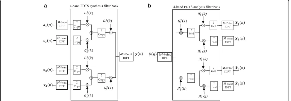
Substituting up-sampling, down-sampling, and cyclic convolution operations of K-band tree-structured filter bank with 2-Copy, 2-Fold, and multiplication operations yields a new structure that we call it as frequency domain tree structure (FDTS) filter bank. Consequently, in order to completely implement the filter bank in the frequency do-main, at the first stage of synthesis part, a set ofKblocks of M-point DFT are required to transfer input blocks to the frequency domain. TheK-band FDTS synthesis filter bank is the subsequent stage, and then,N-point IDFT is required to return these symbols from the frequency domain back to the time domain. At the analysis part, the first stage is an N-point DFT. TheK-band FDTS analysis filter bank andK blocks ofM-point DFT are the subsequent stages.
Figure 5 shows how to implement a 4-band tree-structured filter bank in frequency domain where xið Þn
andx^ið Þn for i= 1 : 4 areM-symbol sequences andyð Þn
andy^ð Þn are 4M-symbol sequences, respectively. In gen-eral case, based on the results of the previous section de-rived for optimum filter bank, when the inputs at the synthesis part are M-symbol sequences, gi
1ð Þn ;gi2ð Þn ;h quency domain coefficients of the filters to be employed at theith level of FDTS filter bank, i.e.,Gi
1ð Þk ;Gi2ð Þk ;Hi1 k
ð ÞandHi
2ð Þk . Finally, it should be noted that since cyc-lic filtering creates a clockwise circular shift, outputs of the analysis part of PR-QMF bank are not exactly equal to the corresponding inputs of synthesis part. In order to compensate such shifts and obtain full re-construction cyclic filter bank, it is enough to change frequency domain coefficients of the synthesis filters for i= 1 : log2K as
In this part, the complexities of frequency and time domain implementations of tree-structured filter bank are com-pared. The complexity is calculated in terms of the number of needed basic operations of additions and multiplications to generate one output block. The filter bank is the optimal K-band tree-structured filter bank where the inputs at the synthesis part are sequences ofM symbols. In general, the coefficients of the filters may be complex numbers, and so, all multiplications and additions are generally complex in-structions. We assume that the filter coefficients and the DFT coefficients of the filters are known at the receiver side and they are registered in the buffer in the initialization step.
3.4.1 Frequency domain implementation
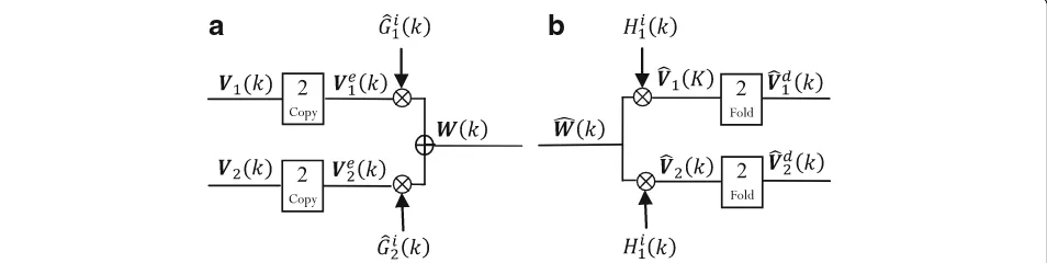
Figure 6a, b shows a typical 2-band frequency domain syn-thesis and analysis filter banks used at the ith level of the synthesis and analysis parts of optimum FDTS filter bank, respectively. Let V1(k),V2(k) be 2i−1M-symbol input
se-quences of 2-band synthesis filter bank. Based on Lemma 1, the next 2-Copy operations generate 2iM-symbol se-quences whose symbols are given as
1e
and, subsequently, the output symbols of synthesis part are obtained as
b a
W kð Þ ¼Ve subsequently, based on Lemma 2, output symbols of 2-band analysis filter bank are obtained as
^
Based on (22), the 2-band frequency domain synthesis filter banks used at theith level of FDTS synthesis filter bank require 2 × 2iM multiplications and 2iM additions. TheK-band FDTS synthesis filter bank consists of log2K
levels, and there areK
2i2-band filter banks at theith level.
Therefore, the number of multiplications and additions performed in the synthesis part of FDTS is
P
log2KIn order to implement K-band synthesis filter bank in the frequency domain, the total basic operations needed consists of basic operations for the calculation ofKblocks of M-point DFT,K-band FDTS, and N-point IDFT.Kis always a power of two andN=MK, thus assuming thatM to be a power of two yieldsNto be also a power of two. Therefore based on the radix-2 FFT algorithm, the overall number of basic operations is obtained as
KM
On the other hand, referring to Eqs. (23–26), 2-band ana-lysis filter banks used at ith level of analysis part need 2 × 2iMmultiplications for two multiplication operators and 2 × 2i−1Madditions for two Fold operators. Therefore, the 2-band analysis and synthesis filter banks used at theith level of FDTS filter bank need equal number of basic mathemat-ical calculations, and consequently, the total number of basic mathematical operations of synthesis and analysis parts of frequency domain implementation are similar.
3.4.2 Time domain implementation
The inputs of theith level of synthesis part are blocks of 2i−1M symbols, and thus, after up-sampling, the size of input blocks is changed to 2iM where half of them are zeroes. Two-band filter banks used at the ith level of analysis part require two 2iM-point cyclic convolutions and one 2iM-point addition at the end. Therefore, num-ber of basic operations performed for the 2-band synthe-sis filter banks used atith level of synthesis part is
22iM2 mults
2iM2iM−1 adds:
8 <
: ð29Þ
The tree is built of log2Klevels where the ith level at
the synthesis part consists of K2i 2-band synthesis filter
bank. Therefore, the total number of basic operations of the synthesis part yields as
P
log2KIn a similar approach, it can be shown that the num-bers of basic operations at the analysis part is equal to
a
b
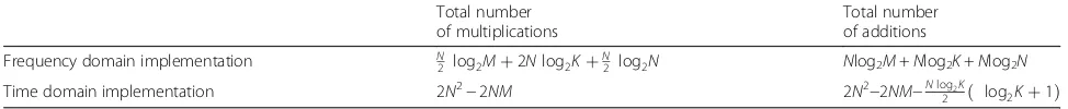
those of the synthesis part. The results are presented in Table 1. It is seen that the complexity of frequency and time domain implementations are of the order of Nlog2NandN2, respectively.
3.5 GOFDM system model based on optimum low-complex filter bank
Deploying the optimum low-complexity tree-structured PR-QMF bank in the generic scheme of Fig. 1 yields the block diagram of Fig. 7 wherein lower case letters denote time domain symbols and higher case letters denote frequency domain symbols. As stated before, the advantage of implementing tree-structured PR-QMF filter bank in frequency domain instead of time domain is reducing the computational complexity of the structure. This advantage is more highlighted at the receiver side wherein the existing FDE implies that the received symbols are transferred to the frequency domain even in case of time domain implementation.
4 Simulation results 4.1 Simulation setup
In what follows, we compare GOFDM with GFDM in terms of spectrum localization, error performance, numerical complexity, and peak to average power ra-tio. Optimum tree-structured PR-QMF bank is employed for GOFDM. In the GFDM structure, the prototype filter is root-raised cosine (RRC) filter with roll-off factor of 0.3. Setting up the configuration pa-rameters of filter banks needs some consideration. Provided that M and K being even numbers GFDM transmit matrix becomes singular [13] but PR-QMF bank does not face such a problem and we are per-mitted to use M and K both as a power of 2. In the simulations, we evaluate two configurations where the number of subcarriers in GFDM and GOFDM schemes for configuration cases 1 and 2 are 256 and
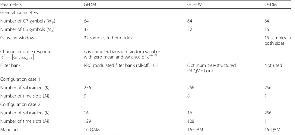
16, respectively. Therefore, we encounter the GFDM limitation of using odd number for M values. Hence, M is chosen as 9 and 129 for GFDM scheme and the nearest power 2 numbers, i.e., 8 and 128 are chosen for GOFDM scheme in the configuration cases 1 and 2, respectively. In two GOFDM configurations, M×K = 2048 and the number of CP symbols is equal to 64; thus, both configurations have similar spectral effi-ciency. When OOB emission is analyzed, configur-ation with large number of subcarriers, i.e., case 1 is taken into account while PAPR is analyzed for config-uration with small number of subcarriers, i.e., case 2. Both configurations are evaluated in terms of error performance and numerical complexity. The channel profile and other simulation parameters are presented in Table 2.
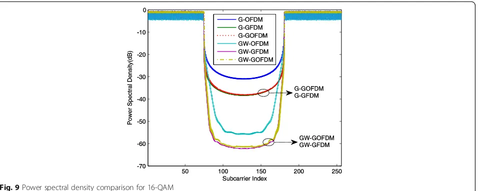
4.2 OOB leakage
In order to reduce OOB emission, the normal ap-proach is to use empty subcarriers at the corner sides of assigned bandwidth. For block-based modulations, abrupt changes of signal between successive blocks result in high OOB emission. Windowing is thus exploited at the transmitter side by multiplying out-put blocks with a window function to smooth abrupt changes and combat the OOB emission. For the case of windowed waveforms in addition to CP, cyclic suf-fix (CS) is also inserted. Through the simulations, G prefix denotes windowed waveform and GW prefix denotes windowing and guard subcarriers are simul-taneously applied for a waveform. According to LTE standard for the case of 256 subcarriers, 150 subcar-riers are occupied as allocated bandwidth. We con-sider six empty subcarriers of each side as guard band and, consequently, power spectral densities (PSDs) leak to other empty subcarriers may be con-sidered as OOB emission. For the case of GOFDM, despite what might be expected, frequency responses of sub-band filters of the K-band tree-structured filter
Fig. 7GOFDM block diagram based on optimum low-complexity tree-structured PR-QMF bank
Table 1Computational complexity of optimum tree-structured analysis/synthesis filter bank
Total number of multiplications
Total number of additions
Frequency domain implementation N
2 log2Mþ2Nlog2KþN2 log2N Nlog2M+Nlog2K+Nlog2N
Time domain implementation 2N2−2NM 2N2−2NM−Nlog2K
bank are disorderly arranged in the spectrum for the case where K is higher than 2. The 4-band frequency split of the spectrum is illustrated in Fig. 8 for ideal band-pass filters. As explained, 4-band tree-structured filter bank has two stages, stage 1 consists of two 2-band filter banks and stage 2 consists of one 2-2-band filter bank. It is seen in Fig. 8 that filter bank of stage 2 reverses the arrangement of two higher sub-bands and the fre-quency response of sub-band 3 comes before sub-band 4. Therefore, the order of 4-band tree-structured filter bank in the spectrum may be shown as {1, 2, 4, 3}. Similarly, 8-band tree-structured filter bank may be considered as a stage of two 4-band tree-structured filter banks prior to one 2-band filter bank. Combining two 4-band tree-structured filter banks using next 2-band filter bank re-verses the order of higher 4-band filter bank, and thus, the sub-bands are ordered in the spectrum as {1,2,4,3,7,8,6,5}.
Following such approach, one can find the order of sub-band filters of K-band tree-structured filter bank in the spectrum is matched to a sequence of gray numbers. In our case study, the 256-number gray sequence starting from 1 shows the order of subcarriers in the spectrum.
Figure 9 compares PSDs of OFDM, GFDM, and GOFDM. In order to evaluate OOB emission, OOB radiation parameter is defined as the ratio of the en-ergy that is emitted into the OOB range and the amount of energy within the allocated bandwidth, i.e.,
OOB radiation¼ jBWj
OOB
j j: R
f∈OOBP fð Þdf R
f∈BWP fð Þdf
ð31Þ
where BW and OOB are the set of frequencies that
are considered as in-band and out of band, respect-ively. The OOB radiations of G-OFDM, G-GFDM,
Fig. 8The frequency split of spectrum in 4-band synthesis tree-structured filter bank of ideal filters
Table 2Simulation parameters
Parameters GFDM GOFDM OFDM
General parameters
Number of CP symbols (Ncp) 64 64 64
Number of CS symbols (Ncs) 32 32 16
Gaussian window 32 samples in both sides 16 samples in
both sides
Channel impulse response
c
! ¼ c0…cNcp−1
ciis complex Gaussian random variable with zero mean and variance ofe−i/10
Filter bank RRC modulated filter bank roll-off = 0.3 Optimum tree-structured PR-QMF bank
Not used
Configuration case 1
Number of subcarriers (K) 256 256 256
Number of time slots (M) 9 8 1
Configuration case 2
Number of subcarriers (K) 16 16 256
Number of time slots (M) 129 128 1
and G-GOFDM are calculated as −25.7, −34.2, and
−33.9 dB, respectively. In case of applying both
win-dowing and guard subcarriers, the OOB radiations of GW-OFDM, GW-GFDM, and GW-GOFDM are
re-duced to −35.6, −50.5, and −49.8 dB, respectively. As
expected, the OOB emissions of cyclic multicarrier modulations are significantly less than that of OFDM. Furthermore, the optimized PR-QMF bank causes GOFDM OOB radiations to be only 0.3 and 0.7 dB more than that of GFDM for the cases of inserting guard subcarriers and employing window and insert-ing guard subcarriers together, respectively. We now compare the bandwidth efficiency for three modula-tions. Noting that the overhead symbols are CP and CS guard symbols in the time domain and empty guard subcarriers in the frequency domain, we define the spectral efficiency as the ratio of useful symbols to the total transmitted symbols during each output block, and then, the spectral efficiency of OFDM, GOFDM, and GFDM are 256þ25664þ16¼0:76;2562569þ649þ32¼0:96 and 2562568þ648þ32¼0:95 , respectively. The results show that GOFDM transmitter yields almost the same level of OOB leakage and spectral efficiency as those of GFDM transmitter.
4.3 Error performance
In the case of GFDM MMSE receiver, an inverse matrix has to be calculated according to changes in noise power. Therefore, GFDM MMSE receiver suffers from high complexity, and DSIC/MF receiver is suggested to use instead. In the earlier study, we have proved, on the assumption of perfect synchronization, GOFDM MMSE receiver which simply consists of one-tap MMSE-FDE and analysis PR-QMF bank is the best GOFDM linear receiver in terms of error performance
[12]. On the other hand, GFDM DSIC/MF receiver is the combination of ZF-FDE, matched filters and DSIC algorithm. One-tap coefficients of MMSE-FDE and ZF-FDE for k= 1:N are defined as 1
C kð Þ and Cð Þk C kð Þ j j2þσ2
w
,
respectively, whereC(k) andσ2
wareN-point DFT
coeffi-cients of channel impulse response and the power of white Gaussian noise, respectively.
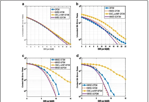
In this study, OFDM, GFDM DSIC/MF with four iter-ations of DISC algorithm, and GFDM MMSE and GOFDM MMSE receivers are compared in terms of error performance for transmitting windowed signals through multipath fading channel when complete synchronization is assumed. At the first step, uncoded BER is analyzed. As seen in Fig. 10a for the case of con-figuration 1, while GOFDM MMSE slightly outperforms OFDM, the BER curves of GFDM MMSE and DSIC/MF receivers are tightly close to that OFDM. For the config-uration case 2 shown in Fig. 10b, GOFDM and GFDM MMSE receivers outperform OFDM in terms of error performance for signal to noise ratio (SNR) larger than 12 and 15 dB, respectively, and the situations are re-versed for SNR smaller than these thresholds. However, there is a considerable gap between GFDM DSIC/MF and OFDM error performance curves which means the negative effect of self-interference at the receiver side of GFDM MF receiver is more serious for configuration case 2 compared with configuration case 1. At the sec-ond step, the parallel concatenated convolutional code (PC-CC) with code rate R= 1/3 is employed for trans-mitter side, and a soft demapper in combination with a turbo decoder with 10 iterations is employed at the re-ceiver side. It is known that the performance of employed advanced receiver depends on the mean square error in the received symbols. Therefore, as seen in Fig. 10c, d, while GOFDM MMSE outperforms
OFDM, there are significant gaps between coded BER curves of DSIC/MF GFDM and OFDM in both configu-rations. On the other hand, the coded error performance of GOFDM MMSE receiver compared to GFDM MMSE receiver depends on the configuration of filter bank and SNR value. It can be verified that BER curve of GOFDM MMSE is slightly lower/higher than that of GFDM MMSE for SNR smaller/larger than 9.7 and 7.5 dB for the configuration cases 1 and 2, respectively.
4.4 Computational complexity
Among the methods introduced to implement GFDM receivers, authors in [18] proposed the lowest complex-ity modem for GFDM zero-forcing and matched filter receivers. However, the proposed method does not sup-port DSIC/MF receiver for the case of multipath fading channel. Therefore, sparse frequency domain processing method introduced in [19] still leads to lowest complex-ity for our case study. Based on this method, the number of multiplications in GFDM DSIC/MF receiver with the configuration ofKsubcarriers andMtime slots ignoring the equalizer complexity is reduced to
N½ð2Jþ1Þlog2MþðJþIÞ þ log2N; ð32Þ
where I is the number of adjacent sub-bands wherein
the frequency response of prototype filter has significant
values and J is the number of iterations for DSIC
algo-rithm.Idepends on the frequency response of prototype
filter and usually is small; however, J depends on the
order of QAM constellation and for the case of large
QAM constellation, large J is required to achieve good
error performance [19].
Ignoring the equalizer part, the complexity of GOFDM receiver with the configuration of K subcarriers and M time slots is equivalent to the complexity ofK-band ana-lysis filter bank with an input block of N = MKsymbols. WhenM andKare a power of two, numerical complex-ity for such configuration is derived in (28).
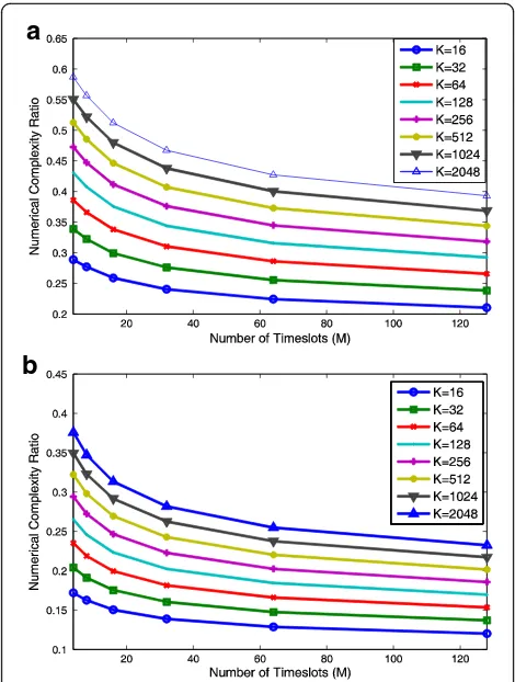
We compare numerical complexity of GFDM DSIC/ MF and GOFDM MMSE receivers in terms of the num-ber of multiplications. In the case of GOFDM,KandM are power of 2 numbers where K is ranged from 16 to 2048 and M is ranged from 4 to 128. For the case of GFDM,Khas the same range butMvalues increased by 1, i.e., M = 5, 9, 17, 33, 65, 129. The values of M in
a
b
c
d
GFDM and GOFDM configurations are not equal; thus, we consider GOFDM configuration parameters as the reference and calculate its complexity relative to GFDM complexity with equalKbutMvalues increased by 1. As seen in Fig. 11a, b, GOFDM MMSE receiver achieves less numerical complexity compared to GFDM DSIC/ MF receiver especially for the case of largeMand largeJ values. For example, in configuration case 1, GOFDM to GFDM complexity ratio for J= 4 and J= 8 are 0.4474 and 0.2724, respectively, and in configuration case 2, this
parameter equals 0.2106 and 0.1203 for J= 4 and J= 8, respectively.
4.5 PAPR
The PAPR of yt(n) sequence is defined as
PAPRðytð Þn Þ ¼
maxjytð Þnj2
averagejytð Þn j2 ð33Þ
Larger PAPR values demand a higher linear range amplifier which is a challenge for designing low-cost terminals. Complementary cumulative density function (CCDF) of PAPR, i.e., the probability that the PAPR ex-ceeds a certain value, is the typical measure to compare different systems in terms of PAPR. PAPR value of mul-ticarrier schemes depends on the number of subcar-riers, and the schemes with a few number of subcarriers perform better than the schemes with large number of subcarriers [20] in terms of PAPR. Authors in [21] showed considering GFDM multicarrier scheme for the uplink of a cellular network wherein only one subcarrier assigned to each user yields smaller PAPR compared to OFDM scheme. Therefore, we consider GFDM and GOFDM with the configuration case 2 for an uplink scenario where one subcarrier assigned to each of 16th users. For the case of OFDM, 16 contigu-ous subcarriers are allocated to each user. As the benchmark, single-carrier FDM system is considered. Then, a pulse-shaping raised cosine filter with roll-off = 0.5 is applied in all schemes. The average values of CCDF of PAPR of transmit signals of the waveforms are shown in Fig. 12. It is seen, OFDM is significantly outperformed by GFDM and GOFDM in terms of PAPR. It can also be verified that GOFDM is superior to single-carrier FDM but it is outperformed by GFDM in terms of PAPR. According to results of previous parts, GFDM transmitter achieves such superiority at the costs of more computational complexity or lower error performance of the receiver side.
a
b
Fig. 11The complexity of GOFDM MMSE receiver relative to GFDM DSIC/MF receiver withI= 2 andaJ= 4 andbJ= 8
5 Conclusions
GOFDM encompasses the architectural advantages of GFDM including high spectral efficiency, low latency, and flexible structure. The novelty of current work relies on exploiting a fast and optimized PR-QMF bank to be employed in the GOFDM structure. As a consequence, GOFDM transmitter yields the same level of OOB leak-age as that of GFDM transmitter and GOFDM receiver yields lower computational complexity compared with GFDM DSIC/MF receiver. Further, it was shown that GOFDM MMSE receiver is superior to OFDM in terms of error performance when modern channel coding is used in the setup. In the similar conditions, GFDM DSIC/MF receiver could not perform adequately, and thus, it was required to use high complexity MMSE re-ceiver for GFDM to achieve acceptable error perform-ance. Furthermore, it was shown employing the configurations of small numbers of subcarriers, large numbers of time slots in GOFDM architecture preserves good spectral efficiency and, besides, yields PAPR even lower than single-carrier FDM scheme. For such config-urations, although GFDM transmitter is superior to GOFDM transmitter in terms of PAPR, GFDM MMSE and DSIC/MF receivers suffer from significant cost of numerical complexity and error performance, respect-ively. In spite of aforementioned advantages, GOFDM has to be precisely evaluated for the case of asynchron-ous transmitters which is a challenging issue for new 5G applications.
Abbreviations
5G:5th generation; CCDF: Complementary cumulative density function; CP: Cyclic prefix; CS: Cyclic suffix; DSIC: Double-side successive interference cancellation; FDE: Frequency domain equalizer; FDTS: Frequency domain tree structure; GFDM: Generalized frequency division multiplexing;
GOFDM: Generalized orthogonal frequency division multiplexing; MF: Matched filter; MMSE: Minimum mean square error; OOB: Out-of-band; PAPR: Peak to average power ratio; PR-QMF: Perfect reconstruction-quadrature mirror filter; PSD: Power spectral density; RRC: Root-raised cosine; ZF: Zero-forcing
Acknowledgements
This work was supported in part by a grant from IPM and in part by a grant from the Iran National Science Foundation under grant 95824827.
Funding
There is no funding for the current research.
Availability of data and materials
The custom codes are available via email to corresponding author.
Authors’contributions
MHA and BHK have been responsible for providing the idea of the paper. MHA has also been responsible for implementation of ideas and performing simulations. MHA, BHK, and AH have been involved in writing the manuscript and proofreading it.
Authors’information
Mohammad Hadi Abbaszadeh received his B.Sc. and M.Sc. degrees from Shiraz University and Iran University of Science and Technology, respectively. He is currently pursuing the Ph.D. degree in Tehran Science and Research
Branch, Islamic Azad University, Tehran, Iran. His research interests include MIMO wireless communications and multicarrier modulations.
Babak Hossein Khalaj received his M.Sc. and Ph.D. degrees from Stanford University. At Stanford, he has been among the pioneering team working on adoption of multi-antenna arrays in mobile networks. He has also been a se-nior member of Advanced Communications Research Institute (ACRI) at Sha-rif University, Tehran, Iran, and the recipient of Alexander von Humboldt Fellowship in 2007–2008.
Afrooz Haghbin received her M.Sc. and PhD degrees from Tehran University and Tarbiat Modares University, respectively. She is currently with the electrical and computer department of Science and Research Branch in Islamic Azad University, Tehran, Iran, as an assistant professor. Her research interests include MIMO wireless communications, channel coding, pre-coding, multicarrier modulation, and estimation theory.
Competing interests
The authors declare that they have no competing interests.
Publisher’s Note
Springer Nature remains neutral with regard to jurisdictional claims in published maps and institutional affiliations.
Author details
1Department of Electrical Engineering, Science and Research Branch, Islamic
Azad University, Tehran, Iran.2Department of Electrical Engineering, Sharif
University of Technology, Tehran, Iran.3School of Computer Science, Institute for Research in Fundamental Sciences (IPM), Tehran, Iran.
Received: 5 June 2017 Accepted: 21 December 2017
References
1. SA Fechtel, A Blaickner, Efficient FFT and equalizer implementation for OFDM receivers. IEEE Trans. Consum. Electron.45(4), 1104–1107 (1999) 2. M Mirahmadi, A Al-Dweik, A Shami, BER reduction of OFDM based
broadband communication systems over multipath channels with impulsive noise. IEEE Trans. Commun.61(11), 4602–4615 (2013)
3. JVD Beek, F Berggren, Out-of-band power suppression in OFDM. IEEE Commun. Lett.12(9), 609–611 (2008)
4. B Farhang-Boroujeny, OFDM versus filter bank multicarrier. IEEE Signal Process. Mag.28(3), 92–112 (2011)
5. V Vakilian, T Wild, F Schaich, St Brink, JF Frigon, in2013 IEEE Globecom Workshops (GC Wkshps). Universal-filtered multi-carrier technique for wireless systems beyond LTE (2013)
6. M Van Eeckhaute, A Bourdoux, P De Doncker, F Horlin, Performance of emerging multi-carrier waveforms for 5g asynchronous communications. EURASIP J. Wirel. Commun. Netw.2017(1), 29 (2017)
7. G Fettweis, M Krondorf, S Bittner, inVTC spring 2009 - IEEE 69th Vehicular Technology Conference. GFDM—generalized frequency division multiplexing (2009)
8. N Michailow, M Matthe, IS Gaspar, AN Caldevilla, LL Mendes, A Festag, G Fettweis, Generalized frequency division multiplexing for 5th generation cellular networks. IEEE Trans. Commun.62(9), 3045–3061 (2014)
9. G Wunder, P Jung, M Kasparick, T Wild, F Schaich, Y Chen, ST Brink, I Gaspar, N Michailow, A Festag, L Mendes, N Cassiau, D Ktenas, M Dryjanski, S Pietrzyk, B Eged, P Vago, F Wiedmann, 5gnow: non-orthogonal, asynchronous waveforms for future mobile applications. IEEE Commun. Mag.52(2), 97–105 (2014)
10. N Michailow, S Krone, M Lentmaier, G Fettweis, in2012 IEEE Vehicular Technology Conference (VTC Fall). Bit error rate performance of generalized frequency division multiplexing (2012)
11. R Datta, N Michailow, M Lentmaier, G Fettweis, in2012 IEEE Vehicular Technology Conference (VTC Fall). GFDM interference cancellation for flexible cognitive radio PHY design (2012)
12. MH Abbaszadeh, BH Khalaj, A Haghbin, Error performance analysis for generalized orthogonal frequency division multiplexing. Computers & Electrical Engineering61, 139–150 (2017)
14. PP Vaidyanathan,Multirate Systems and Filter Banks(Prentice-Hall, Englewood Cliffs, 1993)
15. PP Vaidyanathan, A Kirac, in1997 IEEE International Conference on Acoustics, Speech, and Signal Process.. Theory of cyclic filter banks (1997)
16. AN Akansu, R.A.H.,Multiresolution Signal Decomposition: Transforms, Subbands, and Wavelets(Academic pres, Inc, 1992)
17. AV Oppenheim, RWSchafer, JR Buck, Discrete-Time Signal Processing Upper. Saddle River, N.J., Prentice Hall, (18th ed.). (1999)
18. A Farhang, N Marchetti, LE Doyle, Low-complexity modem design for GFDM. IEEE Trans. Signal Process.64(6), 1507–1518 (2016)
19. I Gaspar, N Michailow, A Navarro, E Ohlmer, S Krone, G Fettweis, in2013 IEEE 77th Vehicular Technology Conference (VTC Spring). Low complexity GFDM receiver based on sparse frequency domain processing (2013) 20. H Seung Hee, L Jae Hong, An overview of peak-to-average power ratio
reduction techniques for multicarrier transmission. IEEE Wirel. Commun.
12(2), 56–65 (2005)