Available Online atwww.ijcsmc.com
International Journal of Computer Science and Mobile Computing
A Monthly Journal of Computer Science and Information Technology
ISSN 2320–088X
IJCSMC, Vol. 5, Issue. 2, February 2016, pg.117 – 124
Orthogonal Frequency Division Multiplexing &
Measurement of its Performance
Rajkumar L. Biradar
Electronics & Telematics Department, G. Narayanamma Institute of Technology & Science, Hyderabad, INDIA
Abstract— OFDM is defined as a form of multi-carrier modulation where the carrier spacing is carefully selected so that each sub carrier is orthogonal to the other sub carriers. As the sub carriers are orthogonal, the spectrum of each carrier has a null at the center frequency of each of the other carriers in the system. Orthogonal Frequency Division Multiplexing (OFDM) is a promising technique to perform multicarrier modulation with maximum utilization of bandwidth and high performance characteristics profile against fading in multipath communication. OFDM has become very popular since its inception. This is used in many communication systems. OFDM is one of the dominant techniques of present day wireless communication and also for future usage in mobile industries. The key requirements for future mobile communications include much higher peak data rate, spectrum efficiency, and user capacity in high mobility environments. OFDM is a kind of Multi Carrier Transmission system where a single data stream is transmitted over a number of subcarriers. OFDM can be used to convert frequency-selective channel into a set of parallel frequency-flat sub channels.
Keywords— Multiplexing, performance, bit error rate, orthogonality.
I. INTRODUCTION
Electronics communication system has revolutionized the face of the world. Communication with someone a mere century back was only possible by physical mode. But now that can be done just by clicking a switch on the telephone pad or by just a click of the mouse. Even live television report, live games telecast could not be possible without wireless communication. A simple communication system consists of a transmitter end which send the data and a receiver end at which the data is received. Usually there received data is not the same as the data sent. Because of the noise present in the medium the signal gets affected and distortion is observed in the signal. Various modulation techniques are under taken in order to ensure that the signal sent is safely available at the receiver end.
Although OFDM was first developed in the 1960s, only recently has it been recognized as an outstanding method for high-speed cellular data communication where its implementation relies on very high-speed digital signal processing, and this has only recently become available with reasonable prices of hardware implementation.
II. LITERATURE SURVEY
The techniques used for wireless communication before Orthogonal Frequency Division Multiplexing are:
Frequency Division Multiplexing (FDM)
Time Division Multiplexing (TDM)
A. Frequency Division Multiplexing (FDM):
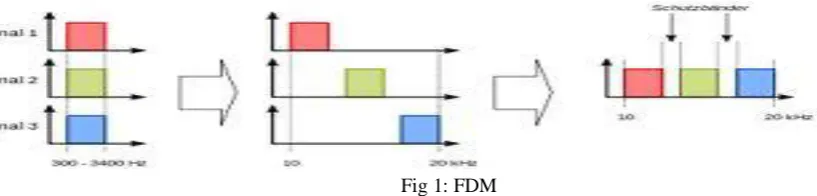
Frequency division multiplexing (FDM) is a technique by which the total bandwidth available in a communication medium is divided into a series of non-overlapping frequency sub-bands, each of which is used to carry a separate signal. This allows a single transmission medium such as a cable or optical fiber to be shared by many signals. An example of a system using FDM is cable television, in which many television channels are carried simultaneously on a single cable. FDM is also used by telephone systems to transmit multiple telephone calls through high capacity trunk lines, communications satellites to transmit multiple channels of data on uplink and downlink radio beams, and broadband DSL modems to transmit large amounts of computer data through twisted pair telephone lines, among many other uses.
In Telephony, the most widely used method of modulation in FDM is single side band modulation, which, in the case of voice signals, requires a bandwidth that is approximately equal to that of the original voice signal. Each voice input is usually assigned a bandwidth of 4 KHz.
Fig 1: FDM
The band pass filters following the modulators are used to restrict the band of each modulated signal to its prescribed range. The resulting band pass filter outputs are combined in parallel to form the input to the common channel.
At the receiving terminal, a bank of band pass filters, with their inputs connected in parallel, is used to separate the message signals on a frequency-occupancy basis. The original message signals are recovered by individual demodulators.
B. Time Division Multiplexing (TDM):
Time-division multiplexing (TDM) is a type of digital (or rarely analog) multiplexing in which two or more bit streams or signals are transferred appearing simultaneously as sub-channels in one communication channel, but are physically taking turns on the channel. The time domain is divided into several recurrent time slots of fixed length, one for each sub-channel. A sample byte or data block of sub-channel 1 is transmitted during time slot 1, sub-channel 2 during time slot 2, etc. One TDM frame consists of one time slot per sub-channel plus a synchronization channel and sometimes error correction channel before the synchronization. After the last sub-channel, error correction, and synchronization, the cycle starts all over again with a new frame, starting with the second sample, byte or data block from sub-channel 1, etc.
III.ORTHOGONAL TIME DIVISION MULTIPLEXING
OFDM is a combination of modulation and multiplexing. Multiplexing generally refers to independent signals, those produced by different sources. So it is a question of how to share the spectrum with these users. In OFDM the question of multiplexing is applied to independent signals but these independent signals are a subset of the one main signal. In OFDM the signal itself is first split into independent channels, modulated by data and then re-multiplexed to create the OFDM carrier. The principle of OFDM system is discussed below.
A. Basic Structure of a Multi-Carrier Transmission Scheme
To overcome the frequency selectivity of the wideband channel experienced by single-carrier transmission, multiple carriers can be used for high rate data transmission. The wideband signal is analyzed (through multiple narrowband filters) into several narrowband signals at the transmitter and is synthesized at the receiver so that the frequency-selective wideband channel can be approximated by multiple frequency-flat narrowband channels. The frequency-non selectivity of narrowband channels reduces the complexity of the equalizer for each sub channel. As long as the orthogonality among the sub channels is maintained, the ICI (inter-carrier interference) can be suppressed, leading to distortion less transmission.
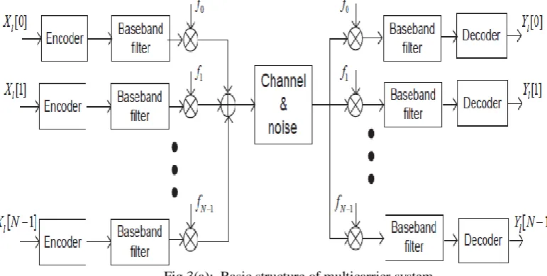
In the multichannel system, let the wideband be divided into N narrow band sub channels, which have the subcarrier frequency of fk, k = 0, 1,2, …. N-1. Figure 3(a) shows the basic structure of a multi-carrier communication scheme, which is one specific form of the multichannel system, where the different symbols are transmitted with orthogonal sub channels in parallel form.
Fig 3(a): Basic structure of multicarrier system
Fig 3(b): Spectral characteristics of multicarrier system
does not use individual band limited filters and oscillators for each sub channel and furthermore, the spectra of subcarriers are overlapped for bandwidth efficiency, unlike the FMT scheme where the wideband is fully divided into N orthogonal narrowband sub channels. The multiple orthogonal subcarrier signals, which are overlapped in spectrum, can be produced by generalizing the single-carrier Nyquist criterion into the multi-carrier criterion.
Fig 4: OFDM transmission scheme implemented using IDFT/DFT
In practice, discrete Fourier transform (DFT) and inverse DFT (IDFT) processes are useful for implementing these orthogonal signals and DFT and IDFT can be implemented efficiently by using fast Fourier transform (FFT) and inverse fast Fourier transform (IFFT), respectively. Since each sub carrier signal is time-limited for each symbol (i.e. not band-limited) an OFDM signal may incur out-of-band radiation, which causes non-negligible adjacent channel interference (ACI). It is clearly seen from figure 4 that the first side lobe is not so small as compared to the main lobe in the spectra. Therefore, OFDM scheme places a guard band at outer subcarriers, called virtual carriers (VCs), around the frequency band to reduce the out-of-band radiation. The OFDM scheme also inserts a guard interval in the time domain, called cyclic prefix (CP), which mitigates the inter-symbol interference (ISI) between OFDM symbols.
C. Modulation
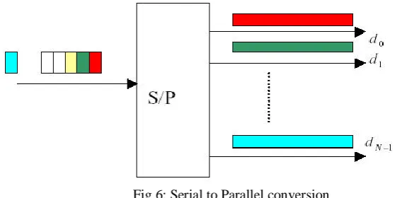
As depicted in figure 6, the input data stream is converted into N parallel data streams through a serial-to-parallel port. The duration of the data is elongated by N times. The OFDM modulation technique is generated through the use of complex signal processing approaches such as fast Fourier transforms (FFTs) and inverse FFTs in the transmitter and receiver sections of the radio. One of the benefits of OFDM is its strength in fighting the adverse effects of multipath propagation with respect to inter symbol interference in a channel. OFDM is also spectrally efficient because the channels are overlapped and contiguous. OFDM is well tested and has been adopted by a number of standards bodies for several applications, including a wired global standard for asymmetric digital subscriber line (ADSL) and for digital audio broadcasting (DAB) in the European market.
Fig 6: Serial to Parallel conversion D. Orthogonal sub carriers
When the parallel symbol streams are generated, each stream would be modulated and carried at different center frequencies as the traditional FDM scheme. The subcarriers centered at frequencies f0, f1, f2 , ... fN - 1 must be orthogonal to each other. The definition of the orthogonality was given in as
Fig 7: An illustration of subcarrier waveforms
where, δ(n-m) is the Dirac-Delta function. In OFDM modulation, the subcarrier frequency fnis defined as, f n = n ∆ f ,
Where,
Here, fs=1/T, ∆f is the entire bandwidth, and Nis the number of subcarriers. Orthogonality can easily be justified for all subcarrier waveforms.
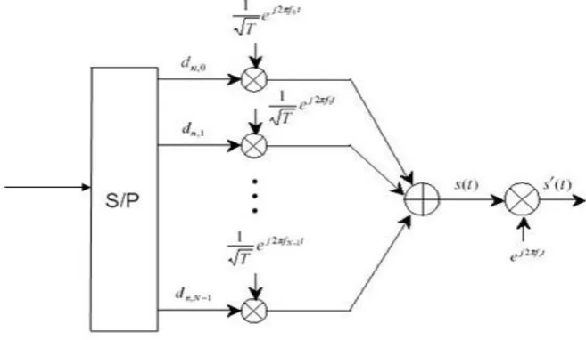
E. Band pass Signaling:
After the modulation by orthogonal sub carriers, all Nsubcarrier waveforms were added together to be up-converted to the pass-band. This resulting signal waveform will be transmitted with a carrier frequency at 2.4G Hz, 5G Hz, 11G Hz or 60 G Hz. Then the band-pass OFDM signal waveform would be sent to power amplifier and antennas. Thus, the transmitted OFDM signal x(t) can be expressed as:
Fig 8: OFDM receiver
At the receiver, the received signal is down-converted to form a base-band signal first. Then, low-pass filters and de-subcarriers are applied to separate subcarrier waveforms. Orthogonality of sub-carriers will ensure that only the targeted subcarrier waveform will be preserved in each sub-band. Ideally, the final detected symbols will be identical to those transmitted.
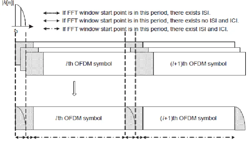
F. ISI and ICI problem
Fig 9: ISI/ICI effect depending on the FFT window start point
In the OFDM scheme if the length of the guard interval (CP) is set shorter than the maximum delay of a multipath channel, the tail part of an OFDM symbol (denoted by a quarter circle) affects the head part of the next symbol, resulting in the ISI. In practice, symbol timing offset (STO) may occur, which keeps the head of an OFDM symbol from coinciding with the FFT window start point.
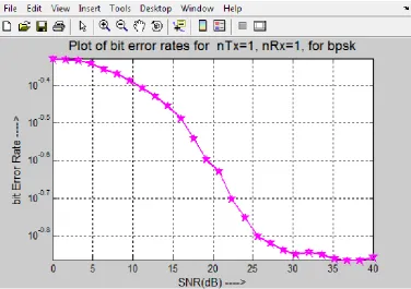
IV.RESULT ANALYSIS
Fig 10: BER Simulation for OFDM in AWGN Channel
Fig 11: BER Simulation for OFDM in Rayleigh Channel
BER performance is better in OFDM compared to FDM. According to simulation results BER performance is better in AWGN channel compared to Rayleigh channel.
A. SNR(dB) B. BER
C. (Rayleigh channel)
D. BER
E. (AWGN channel)
F. 6dB G. 0.4653 H. 0.4531
I. 12dB J. 0.4438 K. 0.3604
L. 18dB M. 0.3979 N. 0.1885
O. 28dB P. 0.2998 Q. 0.0091
Table-1: Comparison of OFDM under Rayleigh Fading Channel and AWGN channel
V. APPLICATIONS
After the IFFT/FFT technique was introduced, the implementation of OFDM became more convenient. The OFDM applications may be divided into two categories-wired and wireless technologies. In wired systems such as Asymmetric Digital Subscriber Line (ADSL) and high speed DSL, OFDM modulation may also be referred as Discrete Multitone Modulation (DMT). In addition, wireless OFDM applications may be shown in numerous standards such as IEEE 802.11 and HiperLAN.
OFDM was also applied for the development of Digital Video Broadcasting (DVB) in Europe, which was widely used in Europe and Australia. In the DVB standards, the number of subcarriers can be more than 8,000, and the data rate could go up as high as 15Mbps. At present, many people still work to modify the IEEE 802.16 standard, which may result in an even higher data rate up to 100Mbps.
VI.CONCLUSIONS
Orthogonal frequency division multiplexing is a form of multi carrier modulation technique with high spectral efficiency, robustness to channel fading, uniform average spectral density capacity of handling very strong echoes and less non linear distortion. But, the increase of the carrier number can decrease the system performance because of the interference between each sub-carrier.
In this proposed work the BER performance of a simple MIMO-OFDM wireless communication system in different fading channels is evaluated. The system structure is very simple. The proposed system has good performance when there are more antennas especially the number of the receiver antennas is greater than that of the transmitter antennas.
REFERENCES
[1]. T. S. Rappaport, Wireless Communications: Principles and Practice, 2nd ed. Singapore: Pearson Education, Inc., 2002.
[2]. K. Feher, Wireless Digital Communications: Modulation and Spread Spectrum Applications. Upper
Saddle River, NJ: Prentice Hall, 1995.
[3]. J. G. Proakis, Digital Communications, 4th ed. NY: McGraw Hill, 2000.
[4]. G. R. Cooper and C. D. McGillem, Modern Communications and Spread Spectrum, NY: McGraw Hill,