R E S E A R C H
Open Access
Cross-tier interference management with a
distributed antenna system for multi-tier
cellular networks
Massa Ndong
*and Takeo Fujii
Abstract
In a multi-tier cellular communication system, the interference from one tier to another, denoted as cross-tier interference, is a limiting factor for the system performance. In spectrum-sharing usage, we consider the uplink cross-tier interference management of heterogeneous networks using femtocells overlaid onto the macrocells. We propose a variation of the cellular architecture and introduce a novel femtocell clustering based on interference cancellation to enhance the sum rate capacity. Our proposal is to use a distributed antenna system (DAS) as an interface to mitigate the cross-tier interference between the macrocell and femtocell tiers. By placing a DAS remote antenna unit (RAU) near a set of femtocells that experience interference from a macrocell user, the DAS can retrieve the interference symbols and feed them back to the femtocells, where each cell can perform interference cancellation when necessary. In addition, the DAS can forward the recovered data to the macrocell base station (MBS); thus, the macrocell user can reduce its transmit power to reach a RAU located closer than the MBS. By distributing the sensor nodes within the macrocell coverage, the proposed scheme can mitigate the cross-tier interference at different locations for several femtocell clusters. Our simulation results show substantial improvement in the network sum rate capacity.
Keywords: Macrocell; Femtocell; DAS; Cross-tier interference mitigation; Heterogeneous networks; Spectrum sharing; Small cell networks
1 Introduction
Next-generation wireless communication demands
enhancement of the cooperation at the multi-tier level to improve the end-user data rate. Cooperation among wireless systems has been demonstrated to be a better alternative for coexisting networks [1]. Contemporary novel wireless network concepts such as heterogeneous networks (HetNets) and multi-tier networks such as femtocells overlaid onto the macrocells require advanced management of the cell load, cross-tier interference, and user access to the spectrum. Spectrum sharing increases to the complexity of meeting the demand in wireless broadband access, thus prompting the emergence of these networks. This process requires the design of spectrum-sharing self-enforcing rules compatible with each individual system [2]. Considering the differences in
*Correspondence: [email protected]
Advanced Wireless Communication Research Center (AWCC), The University of Electro-Communications, 1-5-1 Chofugaoka, Chofu-shi, Tokyo 182-8585, Japan
the transmit power and the near-far problem in two-tier networks [3], our proposal contributes to the design of a coordinator between the two systems, which manages the cross-tier interference and enhances the ergodic sum rate capacity scaling.
In this study, we focus on the cross-tier interference management between a primary system (PS) and a sec-ondary system (SS) in a spectrum-shared scenario. The PS or macrocell tier is composed of a macrocell base station (MBS) and the mobile users that communicate directly with the MBS by default, denoted as macrocell user equipment (MUE). The SS or femtocell tier consists of femtocells. A femtocell is a low-powered user-deployed base station (FBS) that operates in co-channel with the macrocell to deliver high spectral efficiency in closed- or open-access regime [3] to one or two indoor mobile users, denoted as femtocell user equipment (FUE). The femtocell tier constitutes the core technology of small cell networks [4-6].
Femtocells constitute an underlay cell network with the macrocells. Because each FBS is exclusively managed by its end-user, mitigating the cross-tier interference coor-dination similar to that in traditional cellular networks (individually handled by the operators) becomes difficult. Furthermore, the backhaul exchange information between the MBS and the FBSs becomes tedious for a large num-ber of femtocells because the MBS communicates with the femtocells through a gateway. Our proposal aims to address these challenges through the advanced HetNets scheme and innovative femtocell clustering consequent to the proposed introduction of the distributed antenna system (DAS) interface.
We consider the DAS as referred in our references such as [7]. A DAS consists of signal processing modules and remote radio frequency (RF) antenna element modules denoted as remote antenna units (RAUs). Multiple RAUs can share the same signal processing unit denoted as com-mon processing unit (CPU). Each RAU is connected to a CPU by optical fiber. The RAUs are located nearby premises which shelter FBSs. Therefore, different RAUs can cover several small areas in a heterogeneous coverage while sharing the same processing unit. The wired part of the system, made of optical fiber, presents a negligible error rate and delay. The DAS has a common platform role because it can accommodate different wireless ser-vice operators and different protocols. Thus, the DAS is an asset for heterogeneous small cell deployment and can be functionally compared to a radio access network (RAN) aggregation system [8]. As RAN aggregation is considered between operators in [8] to improve throughput and spec-trum efficiency; this study considers femtocell integration by the DAS interface.
In our system model, the FBSs are small base stations located inside the premises of the customers. In a close access operating regime, such FBSs allow communication with only their registered mobile users. The RAUs of the DAS are antenna elements located outside the premises sheltering the FBSs. We consider a path loss exponent dif-ference between the wireless communications of each FBS and its registered FUE and each RAU and an unregistered (to the FBS) MUE.
Reference [9] proposed a cellular architecture based on the DAS to address the coverage scarcity in HetNets. The sum rate of the network improved because of the DAS, which added more degrees of freedom to the network. Recently, HetNets have been considered [10] to imple-ment efficient architecture for broadband access in rela-tion to LTE [11] where DAS is used as HetNet technology enabling system. Interference mitigation in HetNets was considered in [12] through orthogonal resource allocation and relaying. The ergodic capacity analyses can be found in [7], where downlink DAS was considered in multicell environment. Analysis that features cooperation between
DAS antenna element modules and the femtocells located in tall building was presented in [13].
The study in [14] consisted of the cooperation of the base stations equipped with multiple antennas within a cellular system. The proposed interference cancelation was based on multiple antenna signal processing and the exchange of strongly interfering terminal data with the base stations where the received signal decoding remained unsuccessful. The latter base stations performed succes-sive interference cancellation, which used additional mul-tiple antenna processing. Reference [14] assumed that some base stations in the cell can decode multiple user data using their multiple antennas and then exchange the estimated data with the other base stations. Then, the for-warded data were used for interference cancellation when the signal-to-interference-plus-noise ratio (SINR) at the femtocell due to the MUE interference was negligible.
The concept in [14] reflected more of the version of the traditional successive interference cancellation com-bined with the network MIMO. The traditional successive interference cancellation involved the extraction of the estimated interfering signal from the combined signals and the estimation of the desired signal from the differ-ence. The system model in [14] lacked reliability because one of the base stations could be unable to estimate the signal of a strongly interfering terminal from the received combined signals. In contrast to [14], the study in this paper uses signaling without resorting to multiple anten-nas. Because femtocells are indoor systems managed by their end users, it is difficult to apply the schemes in [14] or network MIMO to the different femtocell base stations. In addition, given the recent ubiquity of small cell net-works [6], our proposal in this paper effectively addresses the cross-tier interference issue in a novel way to the best of the authors’ knowledge. Because DAS has already been introduced into cellular systems, we propose to use the DAS as an interface between the macrocell and femto-cell tiers, considering uplink transmission to mitigate the cross-tier interference as follows:
based on the evaluation of the SINR at each FBS in the cluster of femtocells.
• At the macrocell side, the interference from the MUE to the femtocells in the cluster can be mitigated by reducing the MUE transmit power because the DAS retrieves the symbols transmitted by the MUE through the nearby RAU located closer to the MUE than the MBS. Such reduction is constrained by the MUE outage probability at the RAU. The
introduction of the DAS shortens the radio transmission distance of the MUE. This implies a reduction of its transmit power [15].
In addition to the mitigation of the cross-tier inter-ference made possible by the DAS interface, we can derive consequent benefits from our proposal. Instead of exchanging the related information of the strongly interfering terminal as performed in [14] or resorting to network MIMO as done in [7], our proposed interface directly forwards the MUE transmitted symbols where needed in the femtocell cluster. The traditional MBS-FBS direct connection can be used for interference cancella-tion [16]; however, as the number of femtocell clusters increases, the macrocell off-loading role of the femto-cells [6] is compromised by the induced traffic delay in the backhaul. Furthermore, the signal decoding com-plexity individually involves each femtocell that requests interference cancellation, in contrast to the schemes in [7,14]. As stated in the outage analysis, to ensure that the feedback system retrieves the symbols of the MUE(s) causing interference at the FBSs, we propose a cross-tier interference avoidance which consists of prohibiting any FUE transmission susceptible of creating significant interference at the RAU involved in the feedback sys-tem. The overall novelty and contribution of our pro-posal is the use of the distributed direct (wired) links between the DAS (through CPUs and RAUs) and the femtocell tier (FBSs). Consequent to our proposal, the sum rate of the small cell networks improves substan-tially. Such result is confirmed in this study by computer simulations.
The rest of this paper is structured as follows. The sys-tem model and the proposed architecture are described in Section 2. The femtocell clustering concept based on the feedback request is presented in Section 3. Section 4 is devoted to the proposed interference management. The computer simulations are discussed in Section 5, and this paper ends with the conclusion in Section 6.
2 System model and proposed architecture
Figures 1 and 2 illustrate our conventional and pro-posed systems respectively.Opx,x =n,m,uare telecom-munications operators operating in the same region, each having his own MBS. For each operator, frequency
sharing between macrocell and femtocells is considered. Considering the work in [8], we assume that operators can share the DAS through wired optical links connected to the CPUs. We further assume that the RF part of the DAS sensor supports the operator frequency bands. We do not consider the situation where different MBSs share simul-taneously the same RAU. Therefore, this study focuses on a macrocell coexistence with femtocells with regard to the cross-tier interference mitigation in presence of the DAS which is an independent interface to the opera-tors. We assume TDD-OFDMA in this paper. The cases presented in this paper are feasible situations for our pro-posal performance evaluation. As the MUEs are managed by the MBS, if several MUEs are located in the same area, the MBS allocates different frequency bands or time slots for them to communicate. Consequently, we con-sidered one or two MUEs for the cases studied in this paper since we consider frequency sharing in our system model.
2.1 Conventional system: traditional coexistence of the femtocell and macrocell tiers
Each femtocell constitutes an FBS and an FUE (FUE + FBS) as shown in Figure 1. The FBS carries the radio access control of its FUE. Because we assumed a closed regime, the MUE is unable to communicate directly on the wireless link with any FBS. The femtocell radius is on the order of 10 to 50 m. The macrocell tier is com-posed of the MBS and each MUE randomly distributed in the tier. Each MUE attempts to transmit directly to the MBS.
2.2 Cellular architecture modification
Our proposed modification of the conventional system involves the insertion of the DAS in the benchmark. The DAS is represented in Figure 2 by the CPUs and the RAUs. Each RAU is connected directly to a CPU, which is linked to the MBS. We assume that all RAU-CPU and CPU-MBS links are fiber optic links with negligible delay. Signal processing such as minimum mean square estimation (MMSE) through recursive least square algo-rithm and symbol demodulation can be performed at each FBS, and each CPU. A logical implementation of a DAS that cooperates with a network operator can be found in [11].
3 Proposed concept of an femtocell clustering by
DAS
Figure 1Femtocells overlaid onto legacy macrocells.
3.1 Femtocell clustering concept
Our proposal considers a virtual cluster concept. Our concept of ‘cluster’ is defined as an aggregation of sev-eral femtocells (FBSs + FUEs) around a DAS sensor node which assists the FBS at the femtocells in the cross-tier interference cancellation. Due to the small radius of a fem-tocell, we can obtain several femtocells that form a cluster in a random location in the macrocell. Figure 2 shows such clusters, and we denote three of them as FCi, FCj, and FCk associated each with at least a RAU. In FCj,Fj is a femtocell andRj is a RAU. Considering such cluster, we derive the following femtocell clustering concept rel-ative to the DAS elements and the interfering MUE near
the cluster. The MUE transmission generates interference at the cluster. Each FBS evaluates its SINR to assess the need to mitigate the interference. We define a femtocell in outage as a femtocell whose FBS has a SINR below a threshold above which symbol decodability is possible. The femtocells in outage can request the cooperation of the DAS for interference mitigation. The DAS selects the femtocells that request interference mitigation. This selec-tion consists of the femtocell clustering by the DAS. The interference mitigation requires that the DAS retrieves the symbols transmitted by the MUE through its RAU(s) and feed them back to the set of selected femtocells. Thus, each femtocell in the femtocells clustered by the DAS
can retrieve its desired signal by interference cancellation which uses the feedback symbols of the interfering termi-nal(s). Given the distribution of the DAS elements within the macrocell-tier, such cross-tier interference manage-ment can be performed in different clusters. This concept generalizes the interference cancellation scheme in [16].
3.2 Interference cancellation patterns
The introduction of the DAS allows cross-tier interference management under different situations. The channel gains are modeled as independently and identically distributed variables with zero mean and a unit variance. The interfer-ence cancellation for the femtocells selected by the DAS is illustrated in the following cases:
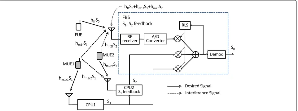
• Figure 3 showsMUE1andMUE2interference at the FBS. On the wireless link, the FBS receives its desired signalS0weighted by the channel gainhff in addition
to the signalsS1andS2which are weighted by the
channel coefficientshm1f andhm2f, respectively. Simultaneously, the feedback system constituted by
CPU1andCPU2retrieves the symbolsS1andS2
through signal processing and forward them to the FBS.CPU1receivesMUE1transmitted signalS1
without interference fromMUE2assumed to be located far enough fromCPU1. Then, it demodulates the received signal in order to forwardS1to both the
FBS andCPU2. After receivingS1,CPU2performs
interference cancellation as detailed in Figure 4 in order to retrieveS2from the wireless signal
hm1RS1+hm2RS2, wherehm1R(hm2R) is the channel
coefficient betweenMUE1(MUE2) and the RAU of
CPU1. The FBS can perform interference cancellation using the forwarded symbolsS1andS2to recoverS0.
• Figure 4 shows the feedback system composed of the MBS and a RAU, wherehm1R(hm2R) is the channel
coefficient betweenMUE1(MUE2) and the RAU of theCPU, andhm1Mis the channel coefficient
betweenMUE1and the MBS.MUE1is close to the MBS such that interference fromMUE2to MBS is negligible, andMUE2is close to the RAU linked to the CPU. When both MUEs interfere at the RAU, the MBS can recoverS1and forward it to the CPU, which
can recover the symbolS2ofMUE2. This process
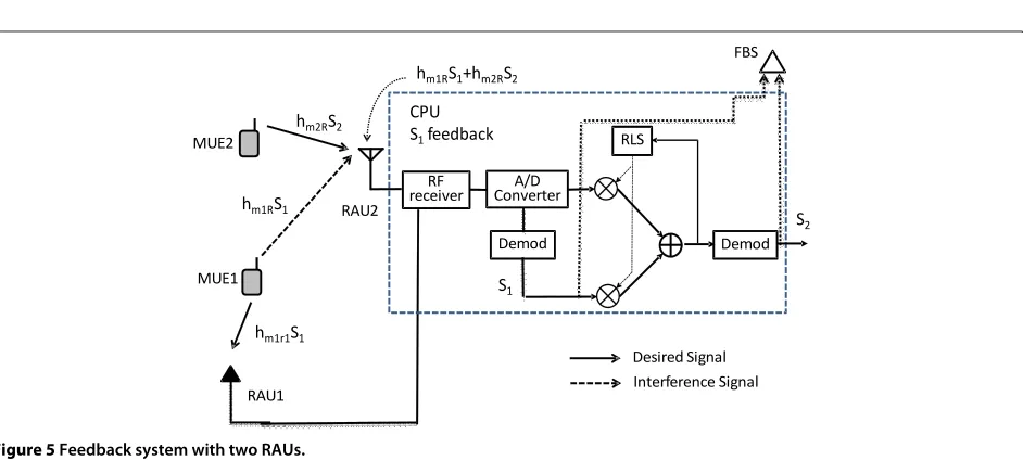
involves a single feedback scheme at the CPU. Then, the two MUE symbols can be forwarded at the femtocells (FBSs connected to the CPU) that experience the interference from the two MUEs. • Figure 5 shows a similar situation to Figure 4 with the
difference that the MBS in Figure 4 is replaced by a RAU. Owing to the presence of the two MUEs and two RAUs sharing a CPU, we propose a power control of the MUEs through the following scheme:
MUE2reduces its transmit power to reach its closest RAU,RAU2.MUE1transmits toRAU1. The CPU can demodulate the symbol received byRAU1
independently of the signal received atRAU2. The CPU connecting the two RAUs retrieves the MUE symbols to feed them back to the FBS for interference cancellation.
In Figure 5, RAU1 receives the symbolS1without
inter-ference. Thus, the RLS module can receive the symbolS1
after demodulation. The equation represents the signals received at the RLS input for interference cancellation. As represented in Figure 5, hm1r1 is not required at the RLS input, therefore is not necessary in the follow-ing matrix representation of the signals for modelfollow-ing the interference cancellation process. Such interference can-cellation scheme has been proposed in our previous work in [16]. In Figure 5, the signals received by the CPU can be represented as follows:
Figure 4Feedback system with CPU and MBS.
S2hm2R+S1hm1R+nR
S1
=
hm2R hm1R
0 1
S2
S1
+
nR
0
,
where hm2R andhm1R are the channel coefficients from MUE2 and MUE1, respectively, to RAU2; hm1r1 is the
channel coefficient from MUE1 to RAU1, and nR is an
AWGN. MUE1 signal at RAU1 is received without inter-ference.S1andS2can be independently decoded by the
signal processing at the CPU because the channel matrix
hm2R hm1M
0 1
is invertible.
Considering that the feedback system can be one of the situations represented in either Figures 4 or 5, we use the notation in Figure 3 to effectively describe the interfer-ence management schemes for the rest of this section. FUE transmits the symbol S0 under channel gain hff to its related FBS. S1 andS2 are transmitted from the two
MUE1 and MUE2, respectively.hm1f andhm2f represent the channel gains from MUE1 and MUE2 to the FBS. We consider MUE1 and MUE2 in Figure 3 for the analysis of theS0recovery under the interference of two MUEs. We
assume that the estimation process ofS0can be performed
as described in [16] by considering the signal feedback from the feedback system to the FBS that receives the combined signalS0hff+S1hm1f+S2hm2f. The interference case that must be considered before the recovery of S0
by the FBS is described as follows: (hm1r2S1+hm2r2S2)
represents the signal received at the RAU resulting from
the transmission of the two MUEs. The feedback of S1
from the MBS to CPU2 allows a single-symbol detec-tion as in [16]. Assuming correct recovery ofS1 andS2
at the CPU, each femtocell in the DAS femtocell cluster can perform interference cancellation using the following relationship:
vided to the FBS by the CPU. The FBS can retrieve S0
by channel matrix inversion. Such channel matrix inver-sion is approximated by the RLS algorithm with mini-mum mean square error equalization. Therefore, the FBS approximates hm1f andhm2f by the RLS algorithm. The detection of S0 using the above matrices notation was
explicitly derived in [16].
3.3 Reception at the RAUs and FBSs
On one hand, the proposed interference management based on the DAS relies on the correct reception of the interfering MUE symbols at the RAU located in the vicin-ity of both the femtocell cluster and the MUE. On the other hand, the inter-femtocell interference may remain at the FBS although the cross-tier interference is cancelled with our proposed feedback. The restriction on the femto-cells transmission due to their closeness to the DAS sensor node is made to allow the DAS sensor node to receive the interfering MUE signal without interference from the close femtocell users.
Thus, we evaluate the probability of successful reception of the transmission of an MUE (FUE) at a RAU (FBS). This evaluation is subject to the MUE (FUE) transmit power control and the combined interference from the set of femtocells that transmit within the cluster. We denote the cardinality of this set by||. We assume that the femto-cells involved in the outage derivation are each located at a distancerfrom the RAU. Such combined interference is subject to the following analysis:
We denote the set of transmission occurrences in the vicinity of the RAU as E = {x1,x2. . .}. Therefore, we
obtain = {∅,{x1},{x1,x2}. . .}as the set of the subsets
that can be constructed fromE, where∅is an empty set. We define the following function over:
f :→R+
→P(X∈), (1)
whereis the set of FUE transmission occurrences from the cluster,P(X ∈)is the total probability of the events constitutingandR+is the set of positive real numbers. To expressP(X∈), we must rely on the DAS femtocell clustering which defines the set of femtocells that request interference mitigation. The cardinality ofis given by:
|| = |{Xs∈M}| + |{Xn∈c}| = |M| + |c| − |M∩c|,
(2)
where s,n ∈ {1, 2, ..||} are the indexes, M is the set of transmission occurrences interfering at the RAU, and cis the set that requires symbol feedback from a CPU for interference cancellation. The probability of success-ful reception at the RAU denoted asPs(r,|M|)is derived
wherePi is the transmit power of the FUE whose trans-mission is received at the RAU considered in Equation 3, θ is the threshold SINR for successful reception, N0
is the noise power, Ptm is the transmit power of the
MUE, dis the distance from the MUE to the RAU, and
λoutandλin are the outdoor and indoor path loss expo-nents,respectively.
Proof.The SINR of the MUE at the RAU is expressed as
SINR= Ptmd
−λout|hM|2
N0+|i=M1|Pir−λin|hi|2
, (4)
wherehMis the channel coefficient between the MUE and the RAU and hi is the channel coefficient from the ith femtocell to the RAU. The outage probability is given by
P(SINR< θ )=1−P(SINR≥θ ), (5) tributed with a variance of one; thus, by computing the moment generating function [18], we can obtain
P(SINR≥θ )=e−θ
N0 PtmdλoutM
t(Y), (7)
wheretis a real number parameter of the moment gener-ating function andYis defined as:
Y = |M|
i=1
Mt(Y)is the moment generating function of the random variableYand parametertis defined as
Mt(Y)=E[etY]
= |M|
i=1
∞
0
e−ste−tdt
= |M|
i=1
1
s+1,
(9)
wheres = PθPir−λin
tmr−λout ande
−tis the density function of an
exponentially distributed random variable with a variance of one. ReplacingMt(Y) by its value in Equation 9 ends the proof.
4 Proposed interference management in
underlay macrocell
As||results partially from the cardinality of the termi-nals that interfere at the RAU, we propose to manage the interference by considering the situation where two differ-ent sets of DAS-selected femtocells are linked to differdiffer-ent DAS elements as denoted by FCjand FCkwhere the MUE denoted byMj interferes in both sets. Because interfer-ence cancellation can be performed at each element of the DAS femtocell clustered in{Xn ∈ c}, the resulting sum rate capacity can be written as follows:
Cc=
|c|
n=1
log2(1+SINRn), (10)
where SINRnis the SINR ofXn ∈ c. Because the feed-back option is unfeasible withMj interfering in FCk, we propose the following time slot based orthogonal resource allocation for the MUE transmissions to improve the network sum rate.
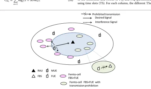
Considering the transmission of an FUE to its FBS, the previous analysis can be applied by substituting the MUE with the FUE and the RAU with the FBS. The set of femtocells surrounding the considered FBS can cause interference and degrade the FBS reception even in the case of feedback. Thus, for a perfect reception at the RAU, we propose to prohibit the FUE transmission close to the RAU as illustrated in Figure 6 used for our simulation model described in Section 5.
4.1 Proposed radio resource allocation for cross-tier interference management in the underlay macrocell In Figure 2, let us considerMjandMkare MUEs interfer-ing at FCj and FCk, respectively. In addition, we assume that Mj interferes at Fj and Fk whereas Mk interfer-ence is restricted to FCk. Rj and Rk are RAUs in FCj and FCk, respectively.Fj (resp.Fk) is a femtocell in FCj (resp. FCk). The interference management through feed-back can be achieved as follows: Rj (resp. Rk) retrieves
Mj (resp. Mk) transmitted symbols, then CPUj (resp. CPUk) feeds back the retrieved symbols toFj (resp.Fk). Such feedback process is enabled by the following radio resource allocation of the MUEs. Table 1 lists the access of the femtocells and MUEs to FCj and FCk partitioned using time slots (TS). For each column, the different TSs
Table 1 Proposed orthogonal radio resource allocation for interference management
Proposed Conventional
TS1:Mj,Fj TS1:Mj
TS2:Mk,Fj,Fk TS2:Mk,Fj
· · · TS3:Fj,Fk
are expressed as TSi, i = 1, 2, 3. At each column TSi, the simultaneously transmitting terminals are denoted as MUE and/or FUE.MjandFjcan transmit simultaneously during TS1becauseMjcan target the MBS or the RAU. The interference ofMjatFjcan be cancelled by the feed-back as illustrated by Figures 4 or 5. In TS2, the
interfer-ence fromMjtoFk is avoided and a transmission similar to TS1can occur inMk andFk whereasFjis beyond the interference range.FjandFkcan transmit simultaneously
in TS3. The DAS enables terminal access management
and permits cooperation if the MUE access to any femto-cell base station is restricted. In the conventional scheme, three TSs are required to avoid interference from the base stations. Because the transmit power decays with the dis-tance, the interference of Mk with Fj is assumed to be negligible.
4.2 Simultaneous transmission without the proposed radio resource allocation
This section describes the conventional scheme of the proposal in Subsection 4.1. We consider FCj and FCk in the absence of the proposed radio resource allocation. We assume a simultaneous transmission of all femtocells and MUEs. Considering the DAS elements, the MUEs can transmit at minimum power to reach the RAU. Although
FjandFk benefit from the interference cancellation from
MjandMk, respectively, in the DAS femtocell clustering,
Fkexperiences interference fromMj. In the conventional
system, Fj and Fk experience low SINR from the high
transmit power of the MUEs.
5 Simulation results and discussion
5.1 Simulation conditions
We use the C language for the simulations presented in this paper. The channel model is a five-path exponential Rayleigh fading. The noise is generated as AWGN. Each user transmits by QPSK modulation to generate the sym-bols from the binary output of the convolutional encoder. Then, OFDM is applied before the signals enter the chan-nel. The OFDM key parameters are listed in Table 2, and the simulation parameters related to the macrocell-femtocell two-tier network are presented in Table 3 which are similar to those in [3]. The noise is added during signal reception whereas the signal fed back to the base sta-tion or the DAS element is free from noise. We use the
Table 2 Simulation conditions
Parameter Value
Bandwidth 5 MHz
Number of subcarriers 512
Useful symbol time 6.4μs
Guard interval 1.25μs
Data modulation OFDM QPSK
Small-scale channel model Rayleigh flat fading
Weight estimation algorithm RLS
Noise AWGN
Convolutional code rate 1/2
Convolutional code constraint length 7
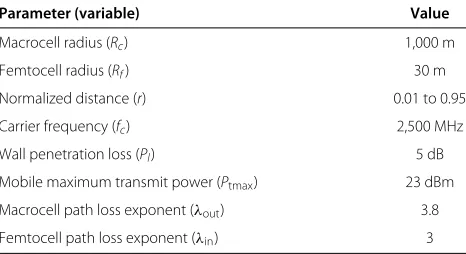
RLS-based MMSE algorithm to recover the data at the receiver for interference cancellation at CPU and/or FBS. The transmit power, positions, and details of the distance path loss model of each user are listed in Table 3. A fixed loss is chosen instead of considering a random lognor-mal shadowing. We use the SINR and capacity evaluation from [19]. The sum rate is then evaluated by Equation 10 whose cumulative distribution function (CDF) is used in the simulation results.
5.2 Performance evaluation and discussion
Our simulation system model is illustrated by Figure 6. In Figure 6, MUE is located at random distances from the femtocells in its vicinity. In our simulation, we con-sider different values ofrfor the variation of the distance between the MUE and different FBSs under the MUE cross-tier interference. Therefore, we evaluate the perfor-mance at the FBS with and without feedback from the feedback system. As represented in Figure 6, the recep-tion of the MUE symbols at the RAU is performed without femtocell interference. In the case of 2 MUEs, we apply the feedback system in Figures 4 or 5 where the MBS or RAU(s) are protected from femtocell interference.
The performance evaluation consists of the computa-tion of the sum rate that considers a femtocell cluster and
Table 3 HUE and MUE femtocell and macrocell parameters
Parameter (variable) Value
Macrocell radius (Rc) 1,000 m
Femtocell radius (Rf) 30 m
Normalized distance (r) 0.01 to 0.95
Carrier frequency (fc) 2,500 MHz
Wall penetration loss (Pl) 5 dB
Mobile maximum transmit power (Ptmax) 23 dBm
Macrocell path loss exponent (λout) 3.8
its neighboring MUE. The sum rate is evaluated using Equation 10 for a given number of mobile terminals. Thus, we add up the rates of the femtocells and MUEs chosen in the situations that illustrate our proposal and the bench-mark. For the two MUEs and two RAUs connected to the same DAS signal processing unit, the DAS can recover the MUE transmitted symbols and forward them to the FBSs that require interference cancellation. In the case of a one-sensor node and two MUEs, one MUE can target the RAU and the other transmits directly to the MBS. The DAS can demand data from the MBS for interference cancellation as depicted in Figure 4. In the presence of more than two MUEs, we assume a time slot-based orthogonal resource allocation for the MUE transmissions as explained in Subsection 4.1. Therefore, the FBS can synchronize with the MUE scheduling. We present the results through the CDF of the capacity.
5.3 Spectral bit rate at RAU and FBSs with|M|
The capacity of the MUE at the RAU or at any FBS is subject to the interference of the surrounding fem-tocells. Thus, we evaluate the capacity considering the transmitting femtocells, i.e.,{Xs ∈ M}. We present the performance of a receiver considering the presence of sur-rounding terminal interference and the proposed interfer-ence cancellation. In Figure 7,NFstands forNo Feedback, i.e., there is no interference cancellation of the cross-tier interference. The curves with NF represent the bench-mark.WF indicatesWith Feedback, i.e., the receiver per-forms interference cancellation using the feedback of the symbols of an interfering MUE.N = iindicates thatiFUEs are interfering at the receiver as in the situation where the FBS retrieves its FUE data with the MUE symbols feed-back and the interference of the neighboring femtocells.
0 1 2 3 4 5 6 7
The curves with WF represent the simulations with inter-ference cancellation by the CPU or the FBS using feedback symbols. The spectral bit rate performance improves with the reduction of the received interference power which decreases in these simulations with the path loss and the interfering terminals are farther located from the receiver.
NF, N = 1 evaluates the situation where the desired
signal of one mobile equipment is received with interfer-ence. Such cases is represented in this study by an MUE transmission received at the RAU while another MUE interference occurs at the reception. Another illustration of NF,N=1 is the interference of an MUE at an FBS receiv-ing the transmission of its FUE without inter-femtocell interference. WF, N=1 represents the interference can-cellation performance where the symbols of the single interfering terminal are fed back to the receiver. In this case, the interference is completely removed. This situa-tion illustrates the performance of the feedback system in Figures 4 or 5.
NF,N= 4 and NF,N= 25 evaluate each the performance at the receiver when the number of interfering mobile terminals increases and without interference mitigation.
WF,N=4 and WF,N= 25 are similar to NF, N= 4, and
NF,N= 25, respectively; with the difference that for NF,
N = 4 and NF,N= 25, the MUE interference at the FBS
has its interference cancelled at the receiver whereas the interference from neighboring femtocells affects the per-formance. The interference mitigation effectively reduces the cross-tier interference to enhance the spectral bit rate.
5.4 Sum rate capacity by proposed radio resource allocation
We consider two MUEs and two femtocells to evaluate the sum rate capacity, as shown in Figure 2 and described
in Subsections 4.1 and 4.2. The situation of FCj and
FCk requires our proposal in 4.1 to improve the sum
rate of the two MUEs (Mk andMj) and the two femto-cells (Fj and Fk). We evaluate the CDF of the sum rate capacity resulting from the performance of the MUEs at the RAUs and the corresponding |c| femtocells for the situation presented by FCj and FCk, as described in Subsections 4.1 and 4.2. conv1 and proposed1 rep-resent the performance of the conventional and pro-posed systems, respectively, as described in Table 1 and Subsection 4.1. conv2 and proposed2 represent the trans-mission without the proposed orthogonal radio resource allocation, i.e., MUE simultaneous transmissions pre-sented in Subsection 4.2. In conv2, FCkexperiences inter-ference from the two MUEs whereas in proposed2, it receives feedback fromMk.
0 5 10 15 20 25
Figure 8MUE interference management spectral bit rate at RAUs and FBSs with|M|.
power decay with the distance adopted for each inter-fering terminal, i.e., as the interinter-fering terminal moves away from the receiving terminal, the interference effect decreases. The proposed resource allocation enhances the DAS femtocell clustering interference mitigation to reduce the combined interference in order to lower the
outage probability at the RAU. With the increase in N
due to the number of terminals that experience high inter-ference mitigated by feedback, the joint interinter-ference can-cellation and DAS femtocell clustering yields significant sum rate improvement compared with the conventional system.
5.5 Average capacity across all users in two-tier network This section shows the effect of inserting the DAS in the two-tier network. The performance metric used in the simulations is the average capacity across all users in the underlay system. The sum rate capacity of the two-tier network can be rewritten as:
Cf =
where SINRi is the average SINR for each femtocell in the DAS clustering, SINRj is the SINR of an interfering MUE on the femtocells. Equation 11 is an expansion of Equation 10. The benchmark is the conventional system described in Subsection 5.3. We have Ni ∈ {4, 14, 25}. We use all the permutations of {4, 14, 25} to evaluate Equation 11 with the permutations of the SINRjs. In the
Figure 9 simulations, N1 = N2 = 3. Each element of
{4, 14, 25}is a number of femtocells clustered by the DAS selection described in Section 3.
0 1 2 3 4 5 6 7 8 9 10
Average capacity across all users (bps/Hz)
CDF
No Feedback MBS Feedback With DAS1 With DAS2
Figure 9Average capacity across all users in the underlay system.
Figure 9 shows the CDFs of the average capacity across all users in different scenarios. The average capacity across all users is defined by:
Cu=
Cf
N1+N2
. (12)
Without the insertion of the DAS, and N2 > 1,
we assume that the radio resource management (by the MBS) assigns orthogonal resource blocks for the MUESs because of their direct transmission to the MBS by default. Thus, there is MUE interference avoidance from the MUEs to the MBS. Each femtocell cluster experiences the interference from one or two MUEs. No Feedback and MBS Feedback represent each the conventional system without the DAS. With No Feedback, each femtocell expe-riences an MUE interference without interference mitiga-tion. MBS Feedback considers a feedback from the MBS; each cluster which experiences an MUE interference can receive a feedback from the MBS for interference cancel-lation. However, the feedback is subject to the orthogonal resource allocation applied for the MUEs directly trans-mitting to the MBS. Because of the MUE transmission scheduling (we assume different time slot allocations in the simulations), the sum rate decreases withN2. DAS1
and DAS2 represent our proposed modification of the two-tier network with the DAS insertion. With DAS1, the MUEs transmit to their respective RAUs. Thus, there is a simultaneous transmission of the MUEs; besides, the DAS can feedback the symbols of each interfering MUE to the femtocells which experience the interference. DAS2 is similar to DAS1 except that in DAS2, the interference cancellation removes all the cross-tier interference.
almost all users get each less than 2 bps/Hz. The per-formance gap obtained by the insertion of the DAS can be interpreted as the traffic unmanageable by the MBS without the DAS.
A synchronization of the transmitting terminals is required in order to achieve our proposed interference cancellation scheme. The FBS and sensor node can adopt the macrocell synchronization by listening to the closest MUE signaling with the MBS. We propose the use of the convex combination algorithm in [20] to update the FBS timing to their nearest neighbors in the wireless interface. Additionally, we propose to feedback the synchronization signaling to the cluster of femtocells from the CPU as the CPU is directly connected to the femtocell cluster without intermediate node.
6 Conclusion
We have presented a novel femtocell clustering in a multi-tier network which was made possible using a proposed HetNet consisting of a DAS on the macrocell and fem-tocell tiers. We proposed the use of DAS as an interface between the two tiers to manage the cross-tier interfer-ence. Consequently, the network cross-tier interference was effectively mitigated, and the sum rate capacity has improved substantially because the DAS femtocell clus-tering linearly scaled the capacity in proportion of the proposed femtocell clustering and its cardinality. The introduction of a DAS within the macrocell overlaid with the femtocells improved the cross-tier interference man-agement and can be used as a benchmark for future HetNet.
Abbreviations
AWGN, additive white Gaussian noise; DAS, Distributed antenna system; FC, femtocell clustering; HetNets, heterogeneous networks; LTE, long-term evolution; MMSE, minimum mean square error; MUE, macrocell user equipment; OFDM, orthogonal frequency division multiplexing; QPSK, quadrature phase shift keying; RAU, remote antenna unit; RF, radiofrequency; RLS, recursive least square; SINR, signal-to-interference-plus-noise ratio.
Competing interests
The authors declare that they have no competing interests.
Received: 9 September 2013 Accepted: 22 April 2014 Published: 7 May 2014
References
1. A Ozgur, O Leveque, D Tse, Hierarchical cooperation achieves linear capacity scaling in ad hoc networks, inIEEE International Conference on Computer Communications (INFOCOM),)Anchorage (IEEE, New York, 2007), pp. 382–390
2. R Etkin, A Parekh, D Tse, Spectrum sharing for unlicensed bands. IEEE J. Selected Topics Commun.25, 517–528 (2007)
3. V Chandrasekhar, M Kountouris, JG Andrews, Coverage in multi-antenna two-tier networks. IEEE Trans. Wireless Commun.8, 4316–4328 (2009) 4. H Claussen, LTW Ho, LG Samuel, An overview of femtocell concept. Bell
Labs Tech. J.13, 221–245 (2008). doi: 10.1002/bltj.20292
5. Y Li, A Maeder, L Fan, A Nigam, J Chou, Overview of femtocell support in advanced WiMAX systems. IEEE Commun. Mag.49, 122–130 (2011) 6. JG Andrews, H Claussen, M Dohler, S Rangan, M Reed, Femtocells: past,
present, and future. Selected Areas Commun. IEEE J.30(3), 497–508 (2012)
7. W Choi, JG Andrews, Downlink performance and capacity of distributed antenna systems in a multicell environment. IEEE Trans Wireless Commun.6, 69–73 (2007)
8. Y Kon, M Ito, N Hassel, M Hasegawa, K Ishizu, H Harada, Autonomous parameter optimization of a heterogeneous wireless network aggregation system using machine learning algorithms, inConsumer Communications and Networking Conference (CCNC),Las Vegas (IEEE, New York, 2012), pp. 894–898
9. D Castanheira, A Gameiro, Distributed antenna system capacity scaling [coordinated and distributed MIMO]. IEEE Wireless Commun.17, 68–75 (2010)
10. RQ Hu, Y Qian, S Kota, G Giambene, Hetnets - a new paradigm for increasing cellular capacity and coverage. IEEE Trans Wireless Commun.
18, 8–9 (2011)
11. H Li, J Hajipour, A Attar, VCM Leung, Efficient HetNet implementation using broadband wireless access with fiber-connected massively distributed antennas architecture. IEEE Trans. Wireless Commun.18, 72–78 (2011)
12. Y Peng, F Qin, Exploring Het-Net in, LTE-advanced system: interference mitigation and performance improvement in macro-pico scenario, in
Proceedings of the IEEE International Conference on Communications Workshops (ICC),Kyoto (IEEE, New York, 2011)
13. T Alade, Z Huiling, Joint signal processing in femtocell based distributed antenna systems in high buildings, inProceedings of the IEEE 72nd Vehicular Technology Conference Fall,Ottawa (IEEE, New York, 2010) 14. K Balachandran, JH Kang, K Karakayali, KM Rege, NICE: a network
interference cancellation engine for opportunistic uplink cooperation in wireless networks. IEEE Trans. Wireless Commun.10, 540–549 (2011) 15. T Alade, H Zhu, H Osman, Spectral efficiency analysis of distributed
antenna system for in-building wireless communication, in2011 IEEE 22nd International Symposium on Personal Indoor and Mobile Radio
Communications (PIMRC),San Francisco (IEEE, New York, 2011), pp. 2075–2079
16. M Ndong, T Fujii, Cross-tier interference mitigation for self organized-self optimized femtocells, inWireless Telecommunications Symposium,London (IEEE, New York, 2012)
17. M Vu, N Devroye, T Vahid, On the primary exclusive region of cognitive networks. IEEE Trans. Wireless Commun.6, 3380–3385 (2009) 18. A Goldsmith, Performance of digital modulation over wireless channels,
inWireless communications, 1st edition(university press, New York, USA, Cambridge, 2005), pp. 187–197
19. JG Andrews, A Ghosh, R Muhamed, Orthogonal frequency division multiple access, inFundamentals of WiMAX understanding broadband wireless networking, 1st edition.Edited by Rappaport TS (Prentice Hall, Massachusetts, 2007), pp. 210–211
20. S Lien, H Lee, S Shih, P Chen, K Chen, Network synchronization among femtocells, inthe second GLOBECOM workshop on femtocell networks,
Houston (IEEE, New York, 2011), pp. 248–252
doi:10.1186/1687-1499-2014-73