Davy-Faraday Research Laboratory,
The Royal Institution o f Great Britain
Department o f Geological Sciences, University College London,
University o f London
Computer Modelling o f Halocarbon Sorption in
Zeolite Y
Thesis submitted for the degree o f Doctor o f Philosophy
by
Naseem Ahmed Ramsahye
ProQuest Number: U642422
All rights reserved
INFORMATION TO ALL USERS
The quality of this reproduction is dependent upon the quality of the copy submitted.
In the unlikely event that the author did not send a complete manuscript and there are missing pages, these will be noted. Also, if material had to be removed,
a note will indicate the deletion.
uest.
ProQuest U642422
Published by ProQuest LLC(2015). Copyright of the Dissertation is held by the Author.
All rights reserved.
This work is protected against unauthorized copying under Title 17, United States Code. Microform Edition © ProQuest LLC.
ProQuest LLC
789 East Eisenhower Parkway P.O. Box 1346
Abstract
The question of cation mobility upon the adsorption o f polar molecules is cmcial in terms of understanding the fundamental chemistry o f basic zeolites, containing exchangeable alkali cations and electron-rich framework oxygen atoms. Experimental techniques have not as yet provided unambiguous answers.
Computational methods, such as molecular dynamics (MD), can help to find answers to some of these questions. The MD study conducted in this thesis (chapters 3 and 4) has shown that sodium cations in NaY are mobile upon sorption of various halocarbon molecules and that cations located in different sites exhibit different types o f mobility. The main migration activity takes place when an SII cation migrates from its site on a six-ring by interacting with the Cl atoms on the chloroform molecule. SI’ cations are then able to traverse a six-ring window to take a position in a vacant SII site.
The defect energy minimization technique has been used to study the energetic barriers to the cation motion throught zeolite six-rings, and the effect o f the aluminium content on these energetic barriers. It has been found that the greater the A1 content, the lower the energy barriers for sodium cations traversing the six-ring from the SIT to the SII site. The six-ring has been found to exhibit a ‘breathing’ motion as the cation traverses through it. The full results are described in chapter 5.
Acknowledgements
First and foremost, I would like to thank my supervisor, Dr. Rob Bell, for all his help, guidance, patience and encouragement throughout my PhD research. Thanks also to Prof Richard Catlow for taking an interest and giving me opportunities to travel to interesting places abroad (MSI trip to San Diego, USA and a NATO ASI on Computational Materials Science in Lucca, Italy). Prof David Price is my UCL supervisor, and I thank him for his assistance on various matters. I also thank the EPSRC for funding my PhD research.
Dr Alex Simperler, Dr Scott Woodley, Dr Sam French, Dr Alexei Sokol, Dr Ben Slater, Dr Dave Coombes, Dr Spencer Braithwaite and Dr Carolyn Barker have been great sources of help on the various computational chemistry theories I’ve used over the three years of my PhD research (as well as being good friends), and so I express my appreciation to them now. Thanks also to Dr Guillaume Maurin, Dr Sylvain Cristol, and Dr Manuel Sanchez-Sanchez. Dr Ben Slater has been very patient with me during the preparation of this thesis, and so extra thanks go out to him.
I must also thank Dr Stefan Bromley, firstly for his help and guidance through the quantum mechanical calculations, secondly for allowing me the chance to work at TUDelft in Holland for a few months (twice), and finally, for being a good friend throughout my PhD. On that note, I also thank Martijn, Mike, Sylvia, Luca, Angel, Bruno, Luuk, Heidi, Paolo, Leon and all the people at TUDelft who made me feel very welcome during my stays in Holland, and Prof Thomas Maschmeyer and TUDelft for allowing and funding my visits.
Table of Contents
A b stract...2
Acknowledgements...3
List of Figures...8
List of Tables... 12
C hapter 1: An Introduction to the Structure, C hem istry and Uses of Zeolites. 16 Introduction... 17
Structure and Composition...17
Cation Placement in Faujasite-structured Zeolites... 22
Uses o f Zeolites...25
Acidity and Basicity in Zeolites...27
Sorption in Zeolites... 29
Adsorption of Halocarbons... 32
Aims of the Thesis... 36
References... 38
C hapter 2: Ç eneral Overview of Some Com putational Chem istry M ethods 41 Introduction... 42
Molecular Mechanics and Atomistic Methods...45
Bond Stretch and Angle Terms... 45
Nan-Bonded Interactions...47
Other Terms...50
Energy M inimisation... 50
Steepest Descents...51
Conjugate Gradients...52
Second Derivative Methods...53
Periodic Boundary Conditions... 54
Long Range Forces: Ewald Summation... 55
Molecular Dynamics... 58
Monte Carlo M ethods... 64
Statistical Ensembles... 67
Electronic Stmcture (or Quantum Mechanical) Methods...6 8 B rief Background to Electronic Structure Methods and Hartree Fock Theory 69 Basis S ets...71
Density Functional Theory...73
Semi Empirical Methods...77
Population Analysis: Mulliken Population Analysis...80
References... 81
C hapter 3: M olecular Dynamics of Cation Motion Upon CHCI3 A dsorption... 83 Introduction... 84
The Forcefleld...8 8 Monte Carlo Simulations... 91
Molecular Dynamics Simulations... 92
Results... 93
Canonical Monte Carlo Simulations...93
Simulation o f the Adsorption Isotherm fo r CHC13 in NaY....97
Molecular Dynamics: Bare Zeolite...99
Cation Motion in Chloroform Loaded NaY Zeolite...103
Loading o f 10 Molecules per Unit Cell...121
Movement o f Chloroform Molecules...121
Effect o f a Rigid Framework on Cation Motion in Sorbate Loaded NaY....126
Evacuation o f the Sorbates...127
Prediction of Vibrational Frequencies... 128
Predictions fo r NaY in the Loaded and Unloaded Zeolite...129
Conclusions...136
Chapter 4: CCI2F2 and CHF3Molecules Adsorbed in NaY Zeolite: A Monte Carlo
and Molecular Dynamics Study... 141
Introduction...142
Methodology...143
Results and Discussion... 146
Docking o f the Molecules...146
Cation motions...149
Molecular Motions...154
Conclusions...158
References... 160
Chapter S: Calculation of the Energetic Barriers to Na Cation Motion through Zeolite Y Six Rings (SI’ to SII)... 161
Introduction...162
Methodology...164
The Shell Model, Defect Energy Minimisation and The Mott-Littleton Method. .164 Creating the Model...167
Potential Parameters...170
Results and Discussion...171
Energetic barriers - general features...173
Effect o f Differing Aluminium Content in the Six Ring...178
Conclusion... 183
References... 185
Chapter 6: Cluster and Periodic DFT Studies of CHCI3 Sorption on Aluminosilicates... 186
Introduction...187
The Cluster Model...187
Methodology... 194
The ONIOM Method...194
Building and Testing the Clusters...195
Embedded Cluster Calculations...199
Periodic D FT Calculations...200
Results and Discussion...201
ONIOM and DMol Cluster Calculations -Adsorption Geometries...201
Adsorption Energies: DMol and ONIOM...206
Cluster Calculation o f Original Monte Carlo Generated Geometry...207
Differences Between DMol and ONIOM....208
Relaxation o f the Cation Position...209
Periodic DFT Calculations - Adsorption Energies and Geometries...211
Periodic Single Point Calculation o f ONIOM Derived Adsorption Site...212
Effect o f the Sodium Relaxation on Six Ring ElectronicCharge...215
Contribution o f the Hydrogen—Oxygen Interaction to the Adsorption Energy...222
Conclusions...226
List o f Figures
1.1 : (a) A 6 ring in a zeolite, (b) An alternative representation of a six ring. 19
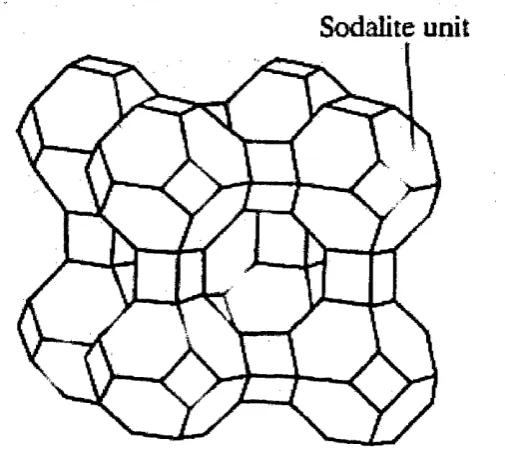
1.2: The mineral sodalite, made up of sodalite cages (units), also known as (3- 20 cages.
1.3: The structure of zeolite A (LT A) 21
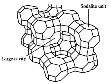
1.4: The structure of faujasite, showing the cavity with the 12 membered ring. 22 1.5: Cation positions and the names of the sites in FAU type zeolite structures. 24 1.6: Possible configurations of halocarbon interactions with cation containing 34 basic zeolites.
1.7: The adsorption isotherm for chloroform sorption on NaY zeolite measured 36 by Kawai et al.
2.1 : The Buckingham potential function for non-bonded interactions 48
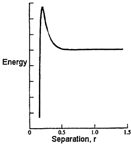
2.2: The Lennard-Jones Potential energy-separation plot, showing the repulsive 49 and attractive components.
3.1: The final configuration of the Monte Carlo mn of 500000 iterations. 95 3.2: The configuration showing the dual interaction whereby the molecule is 96 bound to the zeolite via a hydrogen bond to a framework oxygen atom, and via an electrostatic interaction between a chlorine atom (green spheres) and a sodium cation.
3.3 : A Monte Carlo generated configuration showing the hydrogen atom 97 (white sphere) on a CHCI3 molecule interacting with an oxygen atom on the zeolite framework.
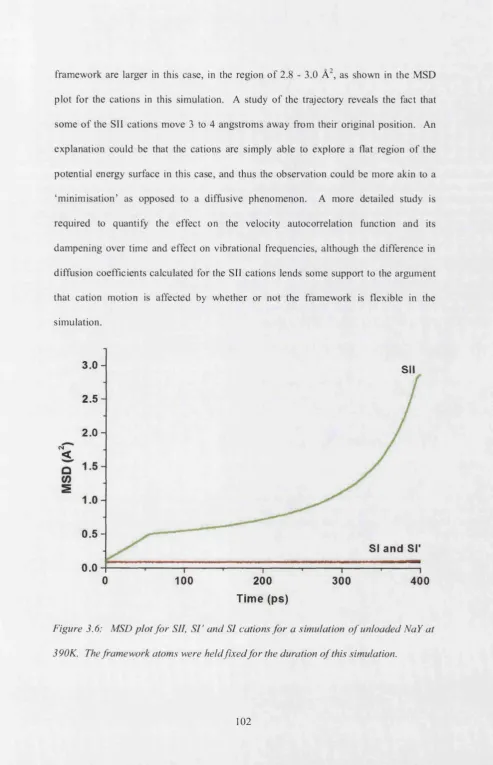
3.4: The calculated isotherm plot for chloroform sorption in NaY zeolite. 99 3.5 : MSD plots for the sodium cations at 390K in unloaded NaY. 101 3.6: MSD plot for SII, ST and SI cations for a simulation of unloaded NaY at 102 390K. The framework atoms were held fixed for the duration of this
simulation.
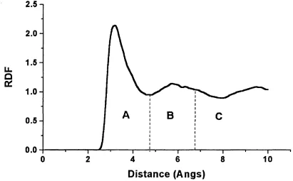
3.7: MSD plot for the SII cations between 0 and 100 ps of MD simulation 105 3.8: MSD plot for SII cations from 100 to 200 ps o f MD simulation 105 3.9: Radial Distribution Function plot for SII cations and Cl atoms between 0 106 and 100 ps of MD simulation.
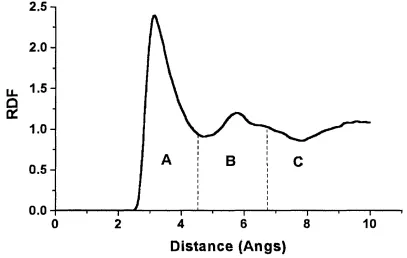
100 and 200 ps o f MD simulation.
3.11 : Movement of sodium cations from SII sites towards the middle of the. 108 supercage over the initial 100 ps of MD simulation.
3.12: MSD plot for SI’ cations between 0 and 100 ps o f MD simulation. I l l 3.13: MSD plot for Site I’ cations between 100 and 200 ps o f MD simulation. 111 3.14: Radial Distribution Function plot for SI’ cations and Cl atoms between 0 1 1 2
and 100 ps of MD simulation
3.15: Radial Distribution Function plot for SI’ cations and CL atoms between 0 113 and 100 ps of MD simulation
3.16: Migration path of sodium cation (yellow balls) from a Si’ site to a SII 115 site.
3.17: MSD plot for SI cations between 0 and 100 ps of MD simulation at 118 270K, 330Kand390K.
3.18: MSD plot for SI cations between 100 and 200 ps of MD simulation at 118 270K, 330Kand390K.
3.19: MSD plot for all cations between 0 and 100 ps o f MD simulation at 119 330K.
3.20: MSD plot for all cations between 100 and 200 ps of MD simulation at 119 330K
3.21 : Graphic showing the various cation motions described. 120
3.22: Orientation of a chloroform molecule adsorped in NaY. 124 3.23: MSD plot for carbon atoms for the MD simulations at 390K, 330K and 125 270K with a loading of 10 molecules per unit cell.
3.24: MSD plot for carbon atoms for the MD simulations at 390K, 330K and 125 270K with a loading of 40 molecules per unit cell.
4.2: A low energy docking configuration of a CFC-12 molecule. 148 4.3: MSD plot for the SI’ cations between 0 and 100 ps o f simulation of NaY 150 zeolite loaded with 40 molecules of CHF3
4.4: MSD plot for the SII cations between 0 and 50 ps of simulation of NaY 151 zeolite loaded with 40 molecules of CHF3
4.5: MSD (in Â^) plot for the SII cations between 50 and 100 ps of simulation 151 of NaY zeolite loaded with 40 molecules of CHF3
4.6: RDF plot for the F - Na interaction during the MD simulation o f CC12F2 153 adsorbed in zeolite NaY.
4.7: RDF plot for the Cl - Na interaction during the MD simulation of CC12F2 153 adsorbed in zeolite NaY.
4.8: Plot of number of sorbate molecules with halogen atoms that are within 156 3.2 Â of a cation for each molecule simulated over 500 picoseconds
4.9: Plot of number of sorbate molecules with hydrogen atoms that are within 156 2.6 À of a framework oxygen atom for each molecule simulated over 500 picoseconds
5.1 : An illustration of the shell model 165 5.2: The partitions of the Mott-Littleton method. 166 5.3 Three o f the migration paths used as points in the Mott-Littleton 168 calculations.
5.4: The diagram o f the six ring through which the migration occurs, showing 169 the A1 atoms(represented by the pink spheres) in the para positions (left) and the meta position (right)
5.5 : A plot of defect energy vs Region 1 radius 172 5.6: energetic barriers for .cation motion between SII’ and SII sites in NaY for 174
1 aluminium atom in a six ring.
5.7: energetic barriers for cation motion between SII’ and SII sites in NaY for 175
2 aluminium atoms in a six ring, arranged in a meta position.
5.8: energetic barriers for cation motion between SII’ and SII sites in NaY for 175
2 aluminium atoms in a six ring, arranged in a para position.
5.10: Labelling scheme of the oxygen atoms for the O - O distances reported 181 in tables 5.5-5.8.
6.1 : Sodalite cage cluster showing the site II cation. 196 6.2: Sodalite cage cluster showing the site I’ cation site. 197 6.3: ‘Extended SII cluster’ showing the site II cation site. 198 6.4: Sodalite cage cluster showing the binding site copied from Monte Carlo 202 docking
6.5: Sodalite cage cluster showing the new binding site. 203
6.6: DMol Optimised ‘Extended SII cluster’ showing the site II cation site and 205
the sorbate molecule in the newly found docking site.
6.7: Optimised ‘Extended SII cluster’ showing the site II cation site and the 208 sorbate molecule docked in the original Monte Carlo generated configuration.
6.8: The cation— oxygen distances are shown in this figure. 210
6.9: The geometry optimised primitive cell of NaY. 214 6.10: Adsorption geometry of the periodic DFT calculation using the PW91 215 functional.
6.11 : Partial charges on the six ring as calculated by the Mulliken scheme for 218 the DMol calculations on the extended cluster.
6.12: Partial charges on the chloroform molecule as calculated by the Mulliken 219 scheme for the DMol calculations on the extended cluster.
6.13: Partial charges on the zeolite SII six-ring as calculated by the Mulliken 220 scheme for the ONIOM calculations on the extended cluster.
6.14: The close-up docking configuration from the periodic DMol calculation 221
(PW91 with the DNP basis set) showing the charges on various atoms, as well as interaction distances
6.15: The T—O bond lengths before and after adsorption for the extended 222 cluster optimised with the DMol program.
6.16: The cluster used to calculate the energy due to the H-Ozeoiite interaction. 224 6.17: The optimised geometry of the calculation to determine the strength of 225
List of Tables
3.1: Partial charges on the atoms in MD simulation 90 3.2: Buckingham terms for the framework-framework and framework-cation 90 interactions
3.3: Lennard-Jones parameters for the sorbate-sorbate, zeoHte-sorbate and 90 cation-sorbate interactions
3.4: Harmonic bond terms from cvff forcefleld for bonding within the 90 chloroform molecules
3.5: Three body terms for the T atoms in the zeolites framework 91
3.6: Harmonic three body terms for chloroform
91
3.7: Simulated and experimental values of the NaY zeolite lattice parameters 93 and volume after optimisation with the new Bell potentials.
3.8: Table of results of the isotherm simulation for chloroform sorption on NaY 98 zeolite
3.9: Masses used to covert molecules/unit cell to mmol/g 99 3.10: Areas of region A from figures 3.9,3.10 and 3.14, 3.15 114 3.11: Areas of region B from figures 3.9,3.10 and 3.14, 3.15 114 3.12: Diffusion coefficients for 10 molecules diffusing through NaY zeolite 123 3.12: Diffusion coefficients for 40 molecules diffusing through NaY zeolite 123
4.1: Partial charges for the atoms in the CCI2F2 molecule 144
4.2: Partial charges for the atoms in the CHF3 molecule 144
4.3 : Lennard-Jones parameters for the non bonded interactions between the 145 sorbate molecule’s consitituent atoms and the cation / framework oxygen atom,
and also the sorbate - sorbate interactions
4.4: Harmonic bonding parameters for the CCI2F2 molecule 145
4.5 : Harmonic bonding parameters for the CHF3 molecule 145
4.6: Harmonic bonding parameters for the CCI2F2 molecule 146
4.8: Diffusion coefficients for CHF3 diffusing in NaY zeolite 158
4.9: Diffusion coefficients for CCI2F2 diffusing in NaY zeolite 158
5.1: The species and their charges used in the Mott-Littleton calculations 170 5.2: The Buckingham potential parameters used in the Mott-Littleton 170 calculations
5.3 : The three body potential parameters used in the Mott-Littleton calculations 170 5.4: Number o f ions corresponding to the various Region 1 radii tested 172 5.5 : Oxygen - oxygen distances (in Â) during the traverse of a Na cation from 181
Sir
site to SII site for the case where there is 1 aluminium in the six ring5.6: Oxygen - oxygen distances (in Â) during the traverse o f a Na cation from 182
Sir
site to SII site for the case where there are 2 aluminiums in the six ring (meta position)5.6: Oxygen - oxygen distances (in Â) during the traverse of a Na cation from 182
Sir
site to SII site for the case where there are 2 aluminiums in the six ring (para position)5.6: Oxygen - oxygen distances (in Â) during the traverse of a Na cation from 182
Sir
site to SII site for the case where there are 3 aluminiums in the six ringCopyright
The copyright o f this thesis rests with the author and no quotation from it or information derived from it may be published without the prior written consent o f the author.
Conventions
Unless otherwise stated, the following colour scheme is used to represent the various atoms in the diagram present in this thesis from chapters 3 to 6.
^
Silicon
^
Aluminium
Oxygen
Sodium
Carbon
O
Hydrogen
^
Chlorine
Chapter 1: An
Introduction to the
Structure, Chemistry and
Introduction
Catalysts essentially increase the rate of reaction, and can be defined as “Any substance that increases the rate o f attainment of chemical equilibrium without itself undergoing chemical chan ge..."/ Catalysts may be in the same phase as the reactants, in which case they are called a homogeneous catalyst, or the catalyst may be in a different phase, known as a heterogeneous catalyst, a prime example being zeolite and zeotype catalysts.
In the industrial world, zeolite catalysts are used on the megaton scale, especially in the petrochemical industry.^ The catalyst industry is said to be worth many millions of US dollars per annum due to the fact that this is the magnitude of monetary profit gained from using catalyst driven processes over alternative, non-catalyst driven processes.^ This is especially true in the case of zeolites. For instance, it is estimated that the use o f zeolite materials has reduced the cost of petroleum refining by ten billion US dollars per annum. The use of zeolites for catalytic purposes has also been driven by environmental concerns and legislation. The use of these solid materials means that there is less toxic waste because, for instance, one can easily separate the required product from the catalyst and by products. Furthermore, zeolites offer an environmentally friendly alternative to toxic and corrosive catalysts.
Structure and Composition
made, and examples include ZSM-5, zeolites A, X and Y, all o f which are commercially important materials/
These minerals are made up of [Si0 4]"^’ and [AlO#]^' tetrahedra, which are comer shared
via oxygen bridges/ Although the aluminium atoms are distributed randomly throughout the stmcture, their relative placings are subject to two mles. The first, Lowenstein's mle, dictates that AIO4 tetrahedra cannot be neighbours with each other,
although Si0 4 tetrahedra can be neighbours with either AIO4 other Si0 4 tetrahedra.
This mle comes about as a result of highly electrostatic repulsion between the negatively charged AIO4 tetrahedra. The second is Dempsey’s Rule, which essentially
states that the aluminium atoms will be distributed as far apart as possible, thereby minimising the number of Al-O-Si-O-Al bridges.
charge compensation is via the “bridging” hydrogen, bonded to a framework oxygen which usually possesses high Bronsted acidity.
The general formula for the composition of a zeolite is Mx/n[(A1 0 2)x(Si0 2)y].mH2 0,
where cations M of valence n neutrahse the negative charges on aluminosilicate framework.^ The Si and A1 atoms are sometimes referred to as T (tetrahedral) atoms.
The tetrahedra are linked at the comers via oxygen atoms, and these links are often represented by straight lines in the literature, with an oxygen in the middle of the line, and T atoms at the comers. It should be noted that in reality T— O—T bonds are rarely linear. This nomenclature is illustrated in figures 1.1a and b, where a 6-ring is shown.
It is also possible to form 4-rings and 5-rings. These rings can join together to form cages that can also join together, and hence the framework of the zeolite is built.
1
/
X o
(a) (b)
Figure 1.1 (a) A six-ring in a zeolite, (b) An alternative representation o f a six-ring.
(Figure taken from reference 3)
sodalite is made from (3-cages connected together via the four rings and packed in a cubic array (i.e. each 4-ring is shared by 2 P-cages).
0
V
a
If the 4-rings in p-cages were connected via oxygen bridges, then zeolite A would be formed. Zeolite A is a synthetic zeolite, and contains a large cavity of molecular dimensions. The cavity in zeolite A has an 8-ring window and has an aperture o f about
4 Angstroms. The stmcture of zeolite-A is shown in figure 1.3. The sodalite cages can be seen at each comer of the cubic array, with the 8-ring window, and the supercage. ^
Sodalite unit
Figure 1.3: The structure o f zeolite A (L T A f
Faujasite is a naturally occurring, but rare mineral, and is built up of sodalite units linked by oxygen bridges between the 6-rings in a tetrahedral array. There is a large
supercage enclosed by this array, and this cage has 1 2-ring windows, with an aperture
Sodalite unit
Figure 1.4: The structure o f faujasite, showing the cavity with the 12 membered ring.^
Cation Placement in Faujasite-structured Zeolites
sodalite cage. These are the three sites normally found to be occupied in dehydrated zeolite Y, Three other cation sites exist in faujasite structures, SIF, SIII and SIIF. SIF sites are located inside the sodalite cages, directly opposite the SII sites. SIII sites are to be found inside the supercage, sitting above a four ring, making up part o f the sodalite cages. They are coordinated to four oxygen atoms, and sit closer to the centre of the supercage than SII cations. SIIF cations are in a similar location to the SIII counterparts, except that they are coordinated to one oxygen atom, as opposed to four. These extra sites can be found occupied in zeolite X. The sites described above are “ideal” crystallographic sites which are useful as reference points. In reality the cations may be displaced from these sites depending on the cation and A1 distribution. The distribution o f the cations amongst the sites in the faujasite structure is also dependent on the exact Si:Al ratio. There is further a general assumption that the distribution is also dependent upon the repulsive Coulombic cation-cation interactions.
Various distributions of cations amongst the sites described above have been proposed for NaY zeolite with a number of Si:Al ratios, determined from both experiment and simulation. Some authors have proposed that sites other than SI, SF and SII are occupied in NaY, for example SIIF. Full occupation of SII sites equates to 32 SII cations in a unit cell. Monte Carlo simulations by Buttefey et al? investigating cation distributions in NaY and NaX have indicated that SI and SII sites are usually filled first, and any extra cations are distributed among SF sites, and SIII or SIIF thereafter.
The model of NaY used in the simulations had the composition Na56Sii36Als6 0 3 9 4, built
distributed among the various possible sites as follows: 6 on SI sites, 18 on SI’ and 32 on SII. Neighbouring SI and SI' sites were not allowed to be populated, due to the aforementioned electrostatic repulsive interactions that would prevent such a configuration of cations. Aluminium atoms were also randomly distributed among the framework T sites, subject to Lowenstein's rule.
Uses of Zeolites
Zeolites are widely used in industry for various purposes. Their ability to act as solid acids and bases makes them suitable for applications such as catalysis and as sorbent materials. Although only about a dozen o f the 126 existing zeolite structures are used for industrial applications, there is a number of different feasible hypothetical structures that are yet to be synthesised, but may have potential uses in the field of catalysis Each structure, either existing or hypothetical, has different shapes and sizes of pores and channels, which is an important factor for the use o f a specific zeolite for a specific purpose in the field of catalysis. In this application, the molecular sieve properties of a zeolite can control which reactant molecules have access to, and which product molecules can depart from the active site. The selection can be on the basis of the reactant shape, and this is known as shape selective catalysis. For example, a zeolite pore may only be big enough to accommodate an alkane o f a certain chain length or shape, and so the branched alkane may not be able to enter the zeolite, whereas a straight alkane could enter the zeolite.^
An example o f this type o f catalysis is in the dehydration o f butanols over zeolite-A with Ca as the extrafi-amework cation. Butan-l-ol can enter the zeolite and react to produce the corresponding alkene, whereas the branched butan-2-ol cannot enter the
zeolite.^
using the zeolite ZSM-5 (Zeolite Socony Mobil-5), where methanol and toluene are the reactants, and three possible products are formed, 1,2-xylene, 1,3-xylene and 1,4- xylene. Only the 1,4-xylene is allowed out o f the pore, as here the methyl groups are in a para position to each other, and this molecular shape means that it can exit the pore.^
Another selection ability of a zeolite is the ability to select on the basis of transition state. The transalkylation of dialkylbenzene serves as an example o f this. A diphenylbenzene is formed as a transition state, splitting to give either the 1,2,4-isomer or the 1,3,5-isomer. However, when this reaction is performed with mordenite, the 1,2,4-isomer is obtained in almost 100% yield, due to the fact that the transition state for the 1,3,5-isomer is too large to fit in the zeolite pore.
Zeolites can act as ion exchangers. For example, zeolite-A can readily exchange Na"^ ions for Ca^"^ ions, making it useful for water softening. It is present in detergents such as washing powder for this particular purpose. Clinoptilolite, a naturally occurring mineral, can exchange Na"^ ions for Cs^ ions, thereby making it useful for the separation and storage of radioactive waste. Zeolite-A can also be used for this purpose due to its ability to recover radioactive strontium.^ Other applications include the use o f the zeolite clinoptilolite in cat litter.
Another use for zeolites lies in the area of gas and solvent separation, making use o f the zeolite as a molecular sieve. Chabazite has been used commercially to absorb polluting SO2 emissions, illustrating the adsorbent property of zeolites. Work has also been
conducted by others in studying the sorption of various gases such as CO2, O2, N2 and
The sorption properties of zeolites can also be applied to removing chlorinated solvents from contaminated groundwater and soils. Separation and storage of halocarbons have important environmental implications.^^
Acidity and Basicity in Zeolites
The fact that zeohtes are important in the heterogeneous catalysis industry is due to their ability to act as solid acids and bases.
Acid zeolites have been widely studied in the past due to the huge number of applications they have in the field of catalysis, especially in the petrochemical industry. Acid sites can be Lewis acids sites, and these sites arise from the presence of extraframework cations in the framework, or the presence of A1 atoms. The acid sites in a zeolite may also be of the Bronsted type, and this is so when protons are present in the zeolite, bonded to the framework oxygen atoms.
Basic zeolites are so due to the fact that aluminium is substituted for silicon in the framework, a consequence of which is that alkali metal cations, such as sodium or lithium, are present in the zeolite to compensate the net negative charge left by this substitution/^ There is an increasing realisation that the distribution of the extra- framework cations may be substantially perturbed upon adsorption of different molecules, leading to changes in the framework electron density and in the mode of physical binding of the guest species. The distribution and siting of the extraframework cations therefore play a major role in the action of zeolites as adsorbents and catalysts, as this may affect the strength of the basic sites.
Group 1 of the periodic table, the basicity of the zeolite will increase. Therefore, if considering zeolites such as A, Y or X substituted with monovalent cations, then in decreasing order of basicity the cations might be Cs > Rb > K > Na > Li. Thus it can be seen that as the extraframework cation radius increase, the basicity o f the zeolite increases. It should also be remembered that the number of cations present will correspond directly to the number of aluminium atoms present, and so the basicity is also determined by the number of aluminium atoms present in the framework.
Sorption in Zeolites
“ ...Catalysis must always be preceded by a d s o r p t i o n . . . T h e term adsorption is applied to describing the accumulation of material (the adsorbate) at a surface. In constrast, the term absorption refers to a bulk phenonmenon. The term sorption has been coined to cover both adsorption and absorption.** In any case, before any catalytic activity can take place, some sort of sorptive phenomena must occur, and hence the importance placed on the study of sorption in zeolite materials.
The sorptive properties of a given zeolite are partly determined by steric factors.*^ The size and shape of the pores and channels of the zeolite structure will have a say in which type of molecule will be able to enter the cage and be adsorbed on the internal surface of the cage, and which type will not. Therefore, a zeolite has the ability to select sorbates on the basis of shape and size (known as shape selectivity).
zeolite either acidic or basic. Such factors will also control whether the sorption is physisorption (van der Waals, dipole, induced-dipole or quadmpole interactions) or chemisorption (where chemical bonds might be formed with the framework). The composition will also have an effect on the energetics o f the adsorption. The presence o f the cations and the aluminium atoms will generate an electric field.^^ This will have a contribution to the adsorption energy of any sorbates in the supercage. Other contributions come from the dispersion-repulsion energy (which can be calculated using a Lennard-Jones potential function, as described in chapter 2) and the polarisation energy of the zeolite. Further terms in the energy calculation depend on permanent dipole and quadmpole moments in the sorbate molecules, and also on sorbate-sorbate interactions.*^
One can measure adsorption isotherms by measuring the amount of adsorbate taken up by the zeolite at a fixed temperature. This can be done at different pressures, and so one can gain an idea of the maximum amount of adsorbate that can be adsorbed before the zeolite pores are saturated.*^'*^.
example, the work of Bell has successfully calculated sorption isotherms and sorption heats for CO2 and N2 adsorbing on NaA zeolite and CaA zeolite using the Grand
Canonical Monte Carlo technique.
The sorption o f krypton on silicalite has also been studied by Calmiano’* using Monte Carlo methods, and again, the results compared well with experimental values o f adsorption heats and isotherms. Molecular dynamics was also used to study the diffusion of small molecules in zeolites, and this allowed the calculation of diffusion coefficients.
ten-membered rings. The ortho-xylene molecules can diffuse through the twelve-ten-membered rings, as this diffusion path is energetically favourable. The authors found that the para- xylene molecules showed larger mobility and could diffuse along a longer path through the 1 0 membered rings and the molecule also diffuses through the 1 2 membered rings.
The authors concluded that the interactions between the molecules also play an important role in determining the nature o f the diffusion of organic molecules in the zeolite, as well as the effects of the pore size.
A number of studies have employed ab initio and first principles methods to study sorption and its effects on zeolite models. Some of these works are further discussed in Chapter 6 of this thesis where they serve as examples of the usefulness of this technique
in the study of sorption.
Adsorption of Halocarbons
In terms of chloroform and CFG sorption, previous work using computational modelling and vibrational spectroscopies^^'^^ has shed light on the mode of binding of CHCI3 and CFG molecules in siliceous F AU, NaY and NaX. From MAS NMR spectra
however there are still substantive questions regarding the role o f the extra-framework alkali cations, although the interpretation of the spectra has led to the suspicion that certain cations migrate upon adsorption of polar molecules. Additional deployment o f x-ray diffraction by Grey et al. has suggested that migration occurred in the case of adsorption of HFG-134^^.
a l concluded that the framework basicity plays a part in the chloroform adsorption. The low field shift of H resonance with increasing framework basicity observed by the authors indicates a hydrogen-bonding interaction, as the nucleophilic framework oxygen polarises the C—H bond of the chloroform molecule. The authors also performed ^^Na MAS NMR experiments and calculated the quadmpole coupling constants for the atoms in sites I' and II. The decrease in these constants upon chloroform sorption was attributed to the migration of sodium cations from site I' to the site II. Bosch et a l
suggest that upon chloroform adsorption, there is a modification of the electron density o f the entire zeolite lattice. They concluded from their NMR data that there is a decrease in site I population, and an interaction of the chloroform with site II cations. The authors also report that there is "an influence on the cations at site SI' " although direct sorbate-cation interaction was mled out in this case due to the inability of the chloroform molecules to enter the sodalite cage. Hence the suggestion that instead, the electron distribution on the zeolite lattice is modified.
shows the different cation sites in NaY zeolite. The III and III’ sites are occupied in zeolite X and not Y*.
Additional NMR experiments and X-ray diffraction by Grey et al. have indicated that cations in the I’ site migrate to site II positions upon adsorption of HFC-134, again possibly attributable due to interaction with the chlorine atom of the molecule.
Bosch et al?^ have proposed possible configurations of the chloroform molecule inside the zeolite, and these are shown in figure 1.6. The proposed configurations also feature
in the work by Kaszkur et who performed synchrotron based diffraction experiments on sorbed chloroform and dichlorobenzene in zeolite Y. The authors indicate that two configurations were possible, represented as Species II and III in figure 1.6. The Species III has the hydrogen atom pointing towards the centre o f the supercage. The paper also notes that there is a decrease in site II occupancy upon chloroform sorption.
X H H
1
K X
/ \
HX 1 X
1
X X X X
\ Î / ( ) '- M* 0 "
\ 1 /
species 1 species I! species III species IV
Figure 1.6: Possible configurations o f halocarbon interactions with cation containing
From their work in measuring the sorption isotherm for chloroform sorption on NaY zeolite, Kawai et have concluded that there is a possible dispersive interaction between the extra-framework cation and the chloroform molecule. Their experiments were performed using gravimetric methods. Kawai et found that gaseous chloroform adsorbing on Na-Y zeolite produced a Langmuir type isotherm, as shown below in figure 1.7. The conclusion drawn from the isotherm was that the absorption proceeds mainly by a dispersive interaction between the chlorine on the chloroform molecule and the Na"^ cation. This was because there was only a slight increase in the maximum loading when the authors used zeolites with more aluminium atoms. Due to the fact that the increase in A1 atoms means an increase in framework basicity, one would expect a larger increase in loading, hence the conclusion drawn by the authors.
Evidence for an electrostatic interaction playing a part in the sorption process was provided by the spectroscopy work of Davidson et al}^. A downward shift in the C-Cl stretching mode indicates a weakening of the C-Cl bond, which was attributed to a Cl- Na electrostatic interaction.
ao "ô E E 3 O E (0 t j 0> Xi *o
<
Equilibrium pressure / kPa
10
20
I I I
nr
30
3 __________
- D D O D O D O D O D D D O D O D O C C m n r i l j l
2! ° °
o Na- Y5 5
A Na- Y42
O N a - Y 344
X
±
0.2
0.4
0.6
P/Po
0.8
1.0
Figure 1.7: The adsorption isotherm fo r chloroform sorption on N aY zeolite measured
by Kawai et al.^^
The interpretation of the NMR spectra is not unambiguous, and so we have turned to computational methods to look into the interactions between the probe molecules and the zeolite framework and cations.
Aims of the Thesis
1. It is an acidic molecule, and can be used as a model compound for halocarbons.
2. There is experimental data available in the form of IR and NMR spectra, and x-ray and neutron diffraction studies with to compare computational results.
the effect of varying aluminium content on the six-ring. This work is described in chapter 5.
Electronic structure calculations can be used to extract information on the effect of the adsorption of these molecules on both the zeolite framework and the adsorbate molecule itself. These techniques can be used to study the changes in electron density on the zeolite framework’s oxygen atoms upon adsorption, and also the polarisation of the adsorbate. One might ask the question of whether the factors controlling adsorption o f molecules such as chloroform and fluoroform are local or whether the extended structure and the presence of cations have a role to play on the energetics of such a process. This would be an important piece of information, as it would help to determine the best model that can be used to represent the zeolite system when modelling such processes and situations. For example, how adequate is the use of a cluster quantum model? Do periodic quantum calculations offer a significant improvement over the cluster version? Details of such a study are reported in chapter 6.
Chapter 1 References
(1) Thomas, J. M.; Thomas, W. J. Principles and Practice o f Heterogeneous Catalysis; VCH, 1996.
(2) Marcilly, C. Studies in Surface Science and Catalysis 2 0 0 1 ,135,37.
(3) Smart, L.; Moore, E. Solid State Chemistry: An Introduction, 2nd ed.; Chapman and Hall, 1995.
(4) Anderson, P. A.; Singer, R. J.; Edwards, P. P. J. Chem. Soc., Chem. Commun.
1991,915.
(6) Anderson, P. A.; Armstrong, A. R.; Porch, A.; Edwards, P. P.; Woodall, L. J. J.
Phys. Chem. B. 1997,101, 9892.
(7) Woodall, L. J.; Anderson, P. A.; Armstrong, A. R.; Edwards, P. P. J.Chem.Soc. Dalton Trans. 1996, 555.
(8) Jaramillo, E.; Auerbach, S. M. Journal o f Physical Chemistry B 1999,103,
9589.
(9) Buttefey, S.; Boutin, A.; Mellot-Draznieks, C.; Fuchs, A. H. Journal o f Physical Chemistry B 2 0 0 1 ,105, 9569.
(10) Fitch, A. N.; Jobic, H.; Renouprez, A. Journal o f Physical Chemistry 1986, 90,
1311.
(11) Foster, M. D. PhD Thesis, UCL, 2003.
(12) Grey, C. P.; Ciraolo, M. F.; Lim, K. H. Abstracts o f Papers o f the American Chemical Society 1998, 215, 047.
(13) Barthomeuf, D. Studies in Surface Science and Catalysis 1991, 65, 157. (14) Ono, Y.; Baba, T. Catalysis Today 1997, 38, 321.
(15) Barthomeuf, D. Catalysis Reviews-Science and Engineering 1996, 38, 521.
(16) George, A. R.; Sanderson, J. S.; Catlow, C. R. A. Journal o f Computer-Aided Materials Design 1993,1, 169.
(17) George, A. R.; Catlow, C. R. A.; Thomas, J. M. Journal o f the Chemical Society-Faraday Transactions 1995, 91, 3975.
(18) Calmiano, M. D. Computer Simulation of Molecular Sorption in Zeolites, University College London, 2001.
(19) Rees, L. V. C.; Shen, D. Adsorption o f gases in zeolite molecular sieves. In
Introduction to Zeolite Science and Practice; 2nd ed.; van Bekkum, H., Flanigen, E. M., Jacobs, P. A., Jansen, J. C., Eds.; Elsevier, 2001.
(20) Yashonath, S.; Thomas, J. M.; Nowak, A. K.; Cheetham, A. K. Nature 1988, 557,601.
(21) Catlow, C. R. A.; Freeman, C. M.; Vessal, B.; Tomlinson, S. M.; Leslie, M.
Journal o f the Chemical Society-Far aday Transactions 1991, 87, 1947.
(22) Sastre, G.; Corma, A.; Catlow, C. R. A. Topics in Catalysis 1999, 9,215.
(23) Mellot, C. F.; Davidson, A. M.; Eckert, J.; Cheetham, A. K. Journal o f Physical Chemistry B 1998,102, 2530.
(24) Mellot, C. F.; Cheetham, A. K. Journal o f Physical Chemistry B 1 9 9 9 ,103,
(25) Davidson, A. M.; Mellot, C. F.; Eckert, J.; Cheetham, A. K. Journal o f Physical Chemistry B2 000,104, 432.
(26) Grey, C. P.; Poshni, F. L; Gualtieri, A. F.; Norby, P.; Hanson, J. C.; Corbin, D. R. Journal o f the American Chemical Society1997,119, 1981.
(27) Bosch, E.; Huber, S.; Weitkamp, J.; Knozinger, H. Physical Chemistry Chemical Physics 1999,1, 579.
(28) Sanchez-Sanchez, M.; Blasco, T.; Rey, F. Physical Chemistry Chemical Physics 1999,1 ,4529.
(29) Mellot, C. F.; Cheetham, A. K.; Harms, S.; Savitz, S.; Gorte, R. J.; Myers, A. L.
Journal o f the American Chemical Society 1998,120, 5788.
(30) Lim, K. H.; Grey, C. P. Journal o f the American Chemical Society2000,122,
9768.
(31) Kaszkur, Z. A.; Jones, R. H.; Couves, J. W.; Waller, D.; Catlow, C. R. A.; Thomas, J. M. J. Phys. Chem. Solids1991,5 2 ,1219.
Chapter 2:
General Overview of Some
Computational Chemistry
Introduction
Chemistry is no longer considered to be a purely experimental su b ject\ and in the areas o f organic and inorganic chemistry computer modelling and simulation techniques play, an important role in applications such as the calculation o f properties o f compounds, elucidation o f structure, designing new materials, prediction o f protein conformations, drug design, the determination o f active site, and numerous other complex problems. This is evident from the extensive use o f computational chem istry methods in academia and industry. Over the past two decades the field has grown rapidly, concurrent with the increase in computer power.
Computational chemistry methods generally fall into two m ain categories: classical methods and electronic structure methods. The form er allows treatm ent o f systems containing up to the order o f 1 0^ atoms in a periodic model, and also treatment o f
individual molecules, w hether small (e.g. small organic molecules) or large (e.g. proteins). This is achieved by the use o f a set o f interatomic potentials, or a ‘forcefield’, which describes the interactions between the constituent atoms (and/or ions) o f the system, w hether they be bonding or non-bonding interactions. These descriptions can then be used to calculate static and dynamic properties o f the system under consideration.
and the adsorption isotherms o f the molecules can be predicted when performed within the Grand Canonical ‘ensem ble’ (to be described later). Energy minimisation techniques can be used in conjunction with Monte Carlo methods to refine docking conformations. M olecular dynamics is used extensively to study diffusive properties o f molecules in zeolites and calculate diffusion coefficients. N ot limited to zeolites, this can be extended to studies in other materials such as ionic m otion in perovskite oxides. One can use the techniques to calculate transport properties o f liquids and transport across surfaces. The study o f the structure o f proteins, carbohydrates and other biomolecules are other applications. Data obtained from such simulations can be used to predict vibrational spectra via autocorrelation functions (velocity or dipole-dipole). As forcefield parameters have improved, comparison o f properties derived from simulations (e.g. docking energies, diffusion coefficients, lattice constants, vibrational frequencies) with experimentally measured ones has become increasingly favourable.
photographie process, and in the modelling o f solid oxide fuel cells, processes where m ovement o f defects has proved to be a key aspect controlling the chemistry.
However, some studies, for example calculation o f transition states and prediction o f N M R shielding constants, and all problems involving the formation or breaking o f bonds, and o f polarisation, require an explicit treatment o f the electrons in a system. For these studies methods such as Hartree-Fock and Density Functional Theory are used. The Hartree-Fock method attempts to solve the Schrodinger equation by finding the optimum coefficients for the set o f wavefunctions that describe the system in question. Density Functional Theory relies on the proo f by Hohenburg and Kohn"^ that unique functionals o f the electron density can be used to calculate the ground state energy o f a system. Although exact solutions o f the Schrodinger equation cannot be obtained for anything more com plex than the hydrogen atom, current electronic structure methods can find solutions to an increasingly high degree o f accuracy. As such these methods have been successfully applied to a num ber o f systems, including complex oxide materials and zeolites. Applications have included studies o f perovskite oxides, e.g. Li intercalation in V2O5 for battery systems^,
determination o f transition states and reaction mechanisms in zeolite catalysts and aluminophosphate materials^, such as in the study o f the sidechain alkylation o f toluene^, studies o f reaction mechanisms on the surfaces o f metals and m etal oxides^’^.
Therefore the computational time required for these calculations is significantly low er than for ab initio methods.
M olecular M echanics and Atom istic M ethods
A tomistic methods are based on the theories o f classical mechanics. They are useful in treating large systems as they calculate the energies o f the system using nuclear positions only, and ignore the positions and motions o f the electrons.
Atoms are treated using a ‘ball and spring’ model, and various equations based on classical physics are used to calculate the energy o f the system. A fundamental aspect o f these calculations is the forcefield, which describes the terms used in the energy calculations. The total energy o f the system is calculated by summing the various contributions, and an example forcefield might contain terms shown below in equation 2.0.
Etotal Ebond Eangle Etorsion Egonbond Eq. 2 . 0
B ond Stretch and A ngle Term s
Ebond refers to the energy contribution from chemical bonds in the system. A function based on Hooke’s Law can be used to describe this contribution, for example,
where k is the spring constant and ro is the equilibrium bond length. The term is actually derived from a truncated Taylor expansion, and higher order terms can be neglected (as is the case here). This decreases the ‘computational cost’ o f the calculation, and eradicates any artificial behaviour that would occur if the higher order term s were to be included. Such behaviour is illustrated if one was to include the cubic term in the series. This would cause the bond energy to tend towards negative infinity at long bond lengths. However, the use o f only the quadratic term is also not ideal, as the frmction tends to positive infinity at long bond distances, and the function is thus usefiil only when the bonds are close to the equilibrium distance. A M orse function can be used instead to remedy the problems expressed by the harmonic function, as for long distances it converges towards the dissociation energy o f the bond, as opposed to positive infinity, which is the behaviour that a harmonic term exhibits.
The form o f a Morse function is:
E = D [1 - exp(a(r-ro))]^ Eq. 2.2
D represents the dissociation energy, and a is a parameter related to the force constant.
Eangle rcfcrs to contributions from three body interactions, and can also be treated using a harmonic function, for example,
Eangle ~ V2 k (0 — Go) Eq. 2.3
possible solution w ould be to include higher order terms. However, the confidence in such high order terms is currently at a low level, as insufficient experimental information is available for the parameterisation o f the ‘higher order’ force constants.
Non-Bo nded Interactions
N on-bonded terms are taken to be the sum o f the van der Waals interactions and the Coulom bic (electrostatic) interactions. The basic form o f the potential for the interaction between two non-bonded particles could be defined as:
V y
^ Eq. 2.4
The first part o f the function refers to the Coulombic interaction, with i and j being the interacting particles, qi and qj referring to the charges on each particle and nj being the distance between them. The contribution from this term is dealt with in many simulations o f periodic systems by the Ewald summation method, which is outlined later on in this chapter.
repulsive component arises from the fact that the decrease in electron density with increasing distance from the nucleus is approximately exponential.
A plot o f energy vs distance for this function is shown in figure 2.1. The majority o f com putational chem istry studies o f the solid state favour the use o f the Buckingham form o f describing non bonded interactions. The function is ideally suited to represent binding in ionic solids, due to the non-directionality o f the bonds in such materials. Despite the fact that the bonding in zeolites is covalent, this approximation performs well for these materials also. Therefore, the Buckingham term has been used to describe the interactions in the zeolite model described later in this thesis.
Energy
0.5 1.0
Separation, r
1.5
Figure 2.1: The Buckingham potential function fo r non-bonded interactions^
jI - A Eq. 2.5
W here A and B are adjustable parameters. The function also has another form i.e.
V(r..) = 4 e o_
r J \ r J
Eq. 2.6
w here e is the well depth, and a is the separation at which the energy is zero. The part o f the function is the repulsive component, and the r"^ part is the attractive component, this is illustrated in figure 2.2. The Lennard-Jones potential is traditionally used when dealing w ith liquid or gaseous systems.
.-1 2
Energy
Separation, r
Figure 2.2: The Lennard-Jones Potential energy-separation plot, showing the repulsive
Other Terms
One final note on forcefleld parameters is that ‘cross term s’ can be used to describe interactions such as simultaneous bond stretching and angle bending interactions. A description o f such interactions can be important, depending on the purpose o f the calculations, an example being the calculation o f phonon frequencies. However, as before, inclusion o f these extra terms would also m ean an increase in computational effort for the calculation. Therefore one m ust balance the accuracy required for a calculation w ith the time and computational pow er available. However, the com puter pow er currently available means that the balance is currently swinging in favour o f accuracy when considering m olecular mechanics calculations o f systems containing about one thousand atoms or ions.
E nergy M inim isation
Steepest Descents
Steepest Descents is a method that moves an atom parallel to the net force on the said atom, and is analogous to walking straight downhill in our energy surface landscape. A direction is chosen, usually the one that has the steepest gradient from the starting point, and a line is followed from that point until the energy along that line is at a minimum. The direction o f the search is then changed to one perpendicular to the current line, and the minimum along that direction is then found, and so forth. There are two ways o f evaluating when a m inim um is reached along a search direction:
1. A minimum is bracketed between two points o f higher energy, and the distance between the two bracket points is reduced by an iterative procedure until a minimum is reached. 2. An arbitrary step approach can be employed where a step o f arbitrary length is taken
along the gradient vector (sk), so that the new co-ordinates after a step k would be
Xk+i = Xk + gkSk, where gk is the step size. The step size is increased if the previous step results in a reduction o f the energy. This continues until the energy increases again. At this stage the algorithm assumes that the search has jum ped over the bottom o f a minimum well, and so the step size is decreased again in order to reach the minimum. The arbitrary step approach can require more steps to reach a minimum but often requires less function evaluations, and so therefore less computer time is used than the line search method.
than once, hence its efficiency can be lower than other methods, such as conjugate gradients.
Conjugate Gradients
This method could also (and more properly) be called the conjugate directions method^ V^* A fter each iteration the search is refined towards the minimum, as the algorithm gives a set o f conjugate directions. This avoids the problem o f searching conformational space that has already been covered, a problem that occurs when using the steepest descents method.
The direction vector hi+i is calculated by adding the gradient, g, at the point i+1 to the previous direction hi, which has been scaled by a constant yi.
K i =gi +i +Yihi E q .2 .7
Yi is defined in one o f two ways:
1. The Polak-Ribiere method: yi = Eq. 2.8
Ei 'Ei
2. The Fletcher-Reeves method: yi = Eq. 2.9
The next gradient is orthogonal to the previous one, and the direction is conjugate to the previous direction. The two methods have similar characteristics, although the F letcher- Reeves method is more robust in certain cases.
Second D erivative M ethods
The Newton-Raphson method uses the second derivatives o f the energy with respect to the co-ordinates, as well as the first derivatives. The second derivatives provide information about the curvature o f the energy function. The method reaches a minimum in one step rather than the two needed for conjugate gradients, because the inverse o f the second derivative matrix can be multiplied by the gradient to obtain a vector towards the nearest minimum. However, this m ethod is computationally expensive as the second derivative matrix (called the Hessian matrix) and the inverse Hessian matrix are expensive to calculate.
Quasi-Newton methods attempt to circumvent this by gradually building up the inverse Hessian matrix at each iteration. Each new position at iteration k is obtained from the current position, x, the gradient, g, and the current inverse Hessian matrix, H.
x„., = X i - H ^ g t Eq. 2.10
appropriate strategy for minimisation might therefore be to use a m ethod such as steepest descents or conjugate gradients when the system is far from the minimum, and then change to a second derivative method as the system nears a minimum, which will result in a faster convergence.
Periodic Boundary Conditions
Having set up a system o f atoms, ions or molecules, one may wish to calculate various bulk properties, and look at the system ’s evolution over time. For solids, and for calculations involving other bulk systems. Periodic Boundary Conditions (PBC) can be applied to the system in order to eliminate surface effects and to allow the calculation o f bulk properties.
In PBC, a unit cell o f volume V, containing N particles is periodically repeated in three dimensions. Calculations are performed on the original cell, but the image cells and their contents are allowed to interact with each other and with the original cell. The num ber o f particles in each cell is kept constant because all the image particles move in the same way as those in the original cell. For example, if a particle were to move from one cell to another, it would be replaced in the original cell by its image from the opposite cell. Here are two methods for treating image particles.
original cell or not. The m aximum cut-off distance for this m odel is h alf o f the smallest unit cell dimension or h alf o f the smallest length o f the simulation box. Simplicity is the main advantage o f this method, as only interactions with the closest particle are considered. The m olecular dynamics algorithm used for the calculations presented in this thesis uses the minimum image convention.
2. Explicit Image Model: All image particles within a specified cut-off distance are considered and allowed to interact with the original particles. This means that image particles from all directions are considered to be interacting with the original at any one time.
L on g R ange Forces: E w ald Sum m ation
The Ewald summation m e t h o d ^ i s used to treat long range electrostatic forces between pairs o f ions within the system. It is a technique that forces the fast convergence o f summations which would otherwise converge slowly.
One might consider the problem by imagining the system being built up as a series o f simulation boxes in three dimensions, which can be imagined in the form o f a sphere. W hen considering such a sphere, the surface area o f the sphere, and therefore also the num ber o f points over w hich the Coulomb summation must take place increases in proportion to r^. This is m uch greater than the rate at which the Coulombic term decays. Considering a spherical array o f simulation boxes with the central box positioned at cubic lattice point n, the sum o f the Coulombic interactions can be written as:
N N
^ M=0 i=l 7=1
r . . +
n Eq. 2.11The prime in the first summation indicates that the scenario where i = j for n = 0 is not included. However the summation detailed above converges very slowly and does not have a finite sum. The slow convergence is also due to the fact that the num ber o f points is proportional to r^, whereas the energy decay is proportional to r'^.
The Ewald method provides a solution to this problem. The summation is converted into two finite series, which both converge much more rapidly. Considering each point charge, a Gaussian charge cloud o f equal value but opposite sign is placed over each charge, thus neutralising the point charges. This now gives a summation o f the point charges plus the neutralising charges, and can be expressed as
^ n = 0 i=l j = l
q j . q . erfc(a f i j + n )
where erfc is an error function, and a is a param eter in the Gaussian distribution. Another summation is also performed, but this time, it is a summation o f the Gaussian charge cloud in reciprocal space, the form o f which is:
The reciprocal sum also converges more rapidly than the original summation, and is added to the first Gaussian distribution, thereby cancelling the charge cloud. The real space and reciprocal space calculations must balance exactly, and to do this the value for a m ust be carefully chosen. Various other error functions also can be taken into account, for example a self-term must be subtracted due to the fact the sum o f Gaussian functions in real space includes the interaction o f each Gaussian with itself. Also a correction term must be added to the calculated energy, depending on the medium in which the simulation takes place.
M olecular Dynam ics
As will be illustrated in later chapters, the m olecular dynamics technique can be useful in studying transport properties o f molecules and ions in zeolites and other porous materials. The technique allows the calculation o f tim e dependent properties, such as diffusion coefficients, something that cannot be calculated using the tim e independent Monte Carlo methods (described later in this chapter). Use o f the technique can help to enhance the interpretation o f ambiguous experimental results, such as implications o f diffusion o f species and the diffusion mechanisms. One can extend the analysis o f the trajectories calculated by a molecular dynamics algorithm to the calculation o f vibrational spectra by the use o f dipole-dipole autocorrelation functions and velocity autocorrelation functions. The molecular dynamics method uses N ew ton’s laws o f motion and applies them to atoms and molecules within a system to calculate their movements and energies over time.
The particles in a system can be imagined to interact through a potential Un, w hich is defined as:^^
Un Eq. 2.14
^ i j
^ 1 #
m i a i - 2 ^ — — r^j
Eq.2.l5
lüj UTjj
nii is the mass o f particle i, ai is the acceleration. This is comparable with the basic equation for calculating the forces on a molecule or atom in molecular dynamics (MD) i.e. N ew ton’s Second Law
F = m a Eq. 2.16
F is the force on the atom or molecule, m is the mass o f the molecule or atom, and a is the acceleration o f the atom. Various algorithms exist for the integration o f the equations o f motion, the most popular being the Verlet a lg o rith m ^ d ev elo p ed in 1967.
The force can be obtained from the potential energy function UN(r). Therefore the force, F, w ould be
dr
Now, a is the second derivative o f displacement with respect to time, therefore - d U ^ d 'r
= m — - Eq. 2.18
dr dt
Integrating twice with respect to time gives:
where k is a constant and u is the initial velocity. A fter displacement, the position o f the atoms after a time, T, can be calculated using a Taylor Series type function:
r(t + T) = r ( t ) + - ^ T + ^ — + Eq. 2.20 & a " 2
V erlet’s algorithm also uses the information from previous step to calculate
dt dt" 2
r(t —T) —r ( t ) —7 7T + —- — ... Eq. 2.21
Adding the two equations gives Verlet expression for calculating the next position:
d^r
r(t + T) = 2 r(t) - r(t - T) + + ... Eq. 2.22