ISSN 2286-4822 www.euacademic.org
Impact Factor: 3.4546 (UIF)
DRJI Value: 5.9 (B+)
Optimization of multilayer composite for solid
rocket motor case using genetic algorithm
MOHAMMED A. ABDALLA
Karary University, Chemical Engineering Department, Sudan
MOHAMED TALBALLA ELSHEIKH
Sudan Academy of Science, Material Research Institute, Sudan
Abstract:
The solid rocket motor (SRM) case of anti-tank weapon has been selected for this work. The structural analysis of the origin SRM under the maximum pressure 18.57 MPa, and thrust of the motor 1254 N, made by ANSYS workbench. The results shown that the safety factor of this case is 1.72. The SRM tube was then replaced with carbon fiber epoxy resin, and the design modified to hold the maximum pressure. The layup angles for composite tube found using Ansys direct Optimization, jointed with structural analysis using ANSYS ACP, show that the safety factor for composite is 2.63, and the ply sequence found by the optimization is (±40, ±50, ±4, ±76, ±28, ±66, ±63, ±87, ±44, ±88, ±28). As expected the weight of the SRM composite tube is less than metallic tube, which was one third of the metallic one.
Key words: carbon fiber, epoxy resin, solid rocket motor case
1. INTRODUCTION
industries, marine, sport equipment and many other products and applications [3].
In the middle of 60th composite winding technology,
introduced to solid rocket motor (SRM) cases manufacturer. In 1970 DuPont discovered the aramid fiber Kevlar, which stronger than fiberglass, and nylon fiber [4]. In 1980th carbon fiber has been discovered with mechanical properties and density superior to those of Kevlar. From that time and then, advanced composites become the most desirable material for rockets and missiles. Generally, SRM composite cases are useful to increase the ranges of missiles due to the gain of load comparable with maraging steel and titanium.
In 1984, graphite, and Kevlar 49 fiber, and LRF 092 resin system used for motor case of Sentry Initial propulsion Test Vehicle (IPTV) [5]. In 1993, Rafoss AS and MAN used intermediate modulus (IM) carbon fiber with a hot cured epoxy resin in a motor case for the Air-to-Air missile [6]. Now days there are numerous types of carbon fibers, which are recognize carbon fibers due to the precursors, or to the ultimate strength and young modulus.
In this work, a metallic rocket motor case replaced with a composite one. The selected materials are carbon fiber as reinforcement, and multi-functional novalac epoxy as a matrix. Ansys Composite PrepPost (ACP), and Ansys static structure, were used for structural analysis. Tsai Hu failure criterion selected as failure mod. The main goal of this study is to optimize the angles for each ply using Ansys direct optimization (DO)
2. MODELING AND SIMULATION
2.1Metal case model
tube, nozzle, and adapter (Figure 2). Table 1 represents the materials, and mechanical properties attached to each part. From the SRM static firing test, the maximum pressure, and thrust obtained, were 18.57 MPa, and 1254 N respectively as shows in Figure 3. Geometry, Static structural within Ansys workbench were used to analyze the metallic SRM. The maximum pressure applied to the tube wall and the convergence part of the nozzle. The pressure applied to the nozzle throat, and to the divergence part of the nozzle about 0.54 of the maximum pressure [7]. The maximum thrust applied to the front of the SRM (Figure 4)
Figure 1 Tow dimensional drawing for the solid rocket motor (SRM)
Figure 2 SRM main parts
Figure 3 SRM Pressure and Thrust vs. time from static firing test
0 100 200 300 400 500 600
0 5 10 15 20
P
re
ss
ur
e
(
M
P
a
)
Time (ms)
0 100 200 300 400 500 6000
500 1000 1500 2000
T
hur
st
(
N
)
Figure 4 Applied pressure and force to the SRM
Table 1 Materials and mechanical properties of SRM parts
Property Tube
Steel 4140
Nozzle Steel 5140
Adapter Al 7075
Density [kg/m3] 7850 7850 2800 Young's Modulus, E
[GPa]
210 200 71
Poisson's Ratio, ν 0.3 0.3 0.33 Yield Strength, σy0.02
[MPa]
650 800 503
Ultimate Tensile, σT [MPa]
1000 1200 573
2.2Composite case model
The steel tube of the SRM replaced with composite material consist of around 60% carbon fiber and 40% epoxy resin. High strength moderate modulus carbon fiber and multifunctional novalac epoxy used for SRM tube. Table 2 Mechanical properties of SRM composite tube represents the properties of the composite material.
The design of the SRM modified in order to hold the gases pressure especially in the connecting parts of nozzle and the rear part with the tube. The maximum thickness of the tube become 5.5 mm instead of 1.5 mm the connected metallic part become inside the tube, which were outside in the original design. Even with this increase in the thickness of the tube wall, the composite tube is still lighter than the metallic tube, which is about the third of the metallic one (Figure 5 and Figure
The tube divided to three parts, the mean tube, nozzle and adapter connections. The angles ranges for optimization which for 11 plies (±θ) from the top. These 11 plies for the tube with thickness 5.5 mm. The target of optimization is to maximize the safety factor using Tsai Wu failure criteria.
Modeling of Composite layup made by Ansys ACP pre-processing. The nozzle and adapter solid parts modeled by mechanical modeler. The combination of the whole system done in static structural, then the internal pressures, and thrust, were similar to the metallic RSM added to the model and solved. The composite tube was then analyzed in Ansys ACP post-processing.
Ansys direct optimization (DO) – MOGA- used to get the optimum ply angles for each layer. From Ansys preprocess the ply angles assigned as input parameters, while the Reserve Factor (RF) assigned to be the main output parameter. Maximization of RF is main purpose of this optimization. The required RF for this application not less than 1.5. For optimization purposes, the ply angle set to be from 0° to ±90°.
Figure 5 the modified RSM with composite tube
1. Composite case 2.Nozzle 3. Rear closure 1 4. Rear closure 2 5. Rear closure
Table 2 Mechanical properties of SRM composite tube
Density [kg/m3] 1540
Longitudinal Young's Modulus, E1 [GPa] 170 Transverse Young's Modulus, E2 [GPa] 8
Poisson's Ratio, υ12 0.28
Poisson's Ratio, υ23 0.4
Tensile Strength, σT1 [MPa] 2700
Tensile Strength, σT2 [MPa] 50
Compression Strength, σc1 [MPa] 1600
Compression Strength, σc2 [MPa] 150
In- plain shear strength, τ12 [MPa] 60 Out –off –plain shear strength, τ12 [MPa] 60
3. RESULTS AND DISCUSSIONS
3.1Metallic RSM
The metallic RSM experienced about 325 MPa maximum stresses (Figure 7). The maximum stresses appear in the convergence part of the nozzle, and this may related to the relatively high pressure applied. The actual pressure of the nozzle convergence gradually decreased starting of the pressure of the combustion chamber, to the throat pressure. The safety factor about 1.721 which acceptable for this working RSM. Table 3 shows these results.
Table 3 metallic SRM structural results
Maximum equivalent (Von - Mises) stress [MPa] 325.31 Maximum equivalent elastic strain [mm/mm] 0.0026
Maximum total deformation (mm) 0.1578
Safety factor 1.721
3.2Composite RSM Optimization Results
The results of the optimization of the composite of the SRM showed in Figure 8,
Figure 9, and
Table 4. The benefit of using fiber in the SRM, over metal, is
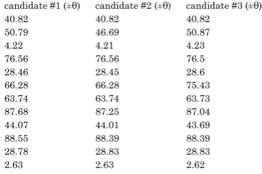
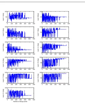
that the SRM need the thickness needed in longitudinal is actually the half of the thickness of circumferential, and this result of extra weight made generally by isotropic material. On the other hand fibers orientation solve this problem, and this clear on the results obtained by optimization, in which case the ply angles distribute between hope and longitude of the tube. Three layers lie around the angle ±45°, which mean equally stresses distribution, and one angle near zero (±4°) serve the longitudinal stresses. For ±4° mainly is not applicable for winding machine but 7° to 10° will do the job. The other 7 layers above 60° and up to near 90° serve the hope stresses. The reserve factor RF, which represent the safety factor of the system, is above 2.6 for the three candidate results represented in
Table 4. Comparing this result with required value for such
application 1.5, that more than required.
The weight gain, around two third of the metallic tube, will support the propulsion effort for the missile specially in large missile, in that case the using of composite material become must.
0 100 200 300 400 500 600
0.5 1 1.5 2 2.5 3
Number of design point
Figure 8 the reserve factor stabilazation during optimaization
Table 4 the optimum ply angles candidates (degree)
candidate #1 (±θ) candidate #2 (±θ) candidate #3 (±θ)
P1 - ModelingPly.1.ply_angle 40.82 40.82 40.82
P3 - ModelingPly.3.ply_angle 50.79 46.69 50.87
P5 - ModelingPly.5.ply_angle 4.22 4.21 4.23
P7 - ModelingPly.7.ply_angle 76.56 76.56 76.5
P9 - ModelingPly.9.ply_angle 28.46 28.45 28.6
P11 - ModelingPly.11.ply_angle 66.28 66.28 75.43
P13 - ModelingPly.13.ply_angle 63.74 63.74 63.73
P15 - ModelingPly.15.ply_angle 87.68 87.25 87.04
P17 - ModelingPly.17.ply_angle 44.07 44.01 43.69
P19 - ModelingPly.19.ply_angle 88.55 88.39 88.39
P21 - ModelingPly.21.ply_angle 28.78 28.83 28.83
Figure 9 the optimized angles of 11 layers of 22 layers; the other 11 lay layers take the negative values
CONCLUSION
In this work, Ansys work bench component, Ansys ACP, and Ansys static structure was used for the structural analysis for the solid rocket motor (SRM). The SRM design was then modified in order to hold the SRM working pressure, which is about 18.57 MPa without losing the benefit of weight gain given by composite material over metallic material. The weight of the composite tube around one third of the metallic tube. The direct optimization using a genetic algorithm was then used to find the optimum ply angles, which maximize the reserve factor
0 100 200 300 400 500 600 0 50 100 L a y e r 1 ( d e g )
0 100 200 300 400 500 600 0 50 100 L a y e r 3 (d e g )
0 100 200 300 400 500 600 0 50 100 L a y e r 5 ( d e g )
0 100 200 300 400 500 600 0 50 100 L a y e r 7 ( d e g )
0 100 200 300 400 500 600 0 50 100 L a y e r 9 ( d e g )
0 100 200 300 400 500 600 0 50 100 L a y e r 1 1 ( d e g )
0 100 200 300 400 500 600 0 50 100 L a y e r 1 3 ( d e g )
0 100 200 300 400 500 600 0 50 100 L a y e r 1 5 ( d e g )
0 100 200 300 400 500 600 0 50 100 L a y e r 1 7 ( d e g )
0 100 200 300 400 500 600 0 50 100 L a y e r 1 9 ( d e g )
0 100 200 300 400 500 600 0 50 100 L a y e r 2 1 ( d e g )
(RF). The required RF for this application is 1.5, by using optimization the RF found around 2.6, and this optimization was converge after more than 500 of generated population over 11 parameters which were the ply angles. The optimization of ply angle generated different ply angles value which is different from usual ply staking where maximum two or three orientation angles were used among all layers. Now days the flexibility of winding machines make it easy to handle with different ply angles sequence which introduce much efficiency.
REFERENCES
[1] Park JS, Hong CS, Kim CG, Kim CU. Analysis of filament wound composite structure considering the change of winding angles through the thickness direction. Composite Structures. 2002;55:63-71.
[2] Bakaiyan H, Hosseini H, Ameri E. Analysis of multi-layered filament-wound composite pipes under combined internal pressure and thermomechanical loading with thermal variations. Composite Structures. 2009;88:532-41.
[3] Hung PL. Investigation of The Stability of
Metallic/Composite-Cased Solid Propellant Rocket Motors under External Pressure [Dissertation]. Virginia Virginia Polytechnic Institute and State University, 1998.
[4] Peters ST. Composite filament winding. Materials Park: ASM International, 2011.
[5] Maheshwari M, Grover RL. Development of an Advanced Composite Rocket Motor Case for Internal and External Load
Environments. AIAA/SAE/ASME 20th Joint Propulsion
Conlerence. Cincinnati, Ohio: American Institute of Aeronautics and Astronautics (AIAA); 1984. p. 1 - 8.
AIAA / SAE/ASME/ASEE 29th Joint Propulsion Conference and
Exhibit. Monterey, Calafornia: American Institute of Aeronautics and Astronautics (AIAA); 1993. p. 1 - 12.
[7] Sutton GP, Biblarz O. Rocket propulsion elements. 8th ed. Hoboken, N.J.: Wiley, 2010.