Design and Test of a 0.3 THz Compact Antenna Test Range
Chi Liu* and Xuetian Wang
Abstract—The terahertz (THz) compact antenna test range (CATR) detection technology is the foundation of terahertz target recognition technology. It provides an excellent plane wave area which can well meet the far-field condition of antenna pattern and RCS test. Based on the microwave single reflector CATR system that we have designed before, this paper mainly aims at designing a 0.3 THz CATR system and then gives the simulation model of the system errors. After the preparation of the above work, we begin to detect its 0.3 THz band plane wave field, and the final test results can be used for further application.
1. INTRODUCTION
Terahertz (THz) technology is the research on electromagnetic wave whose frequency is from 0.1 THz to 10 THz. Currently, the three major academic hotspots in terahertz field are THz radar technology, THz communication technology and target detection technology. With the development of new science technology, it becomes more and more important to study the THz electromagnetic radiation and scattering characteristics of radar antenna, whole satellite and other space targets. THz wave is suitable for large signal bandwidth and narrow antenna beam, so it is conducive to achieving high-resolution imaging of the target [1–4]. However, when we focus on the research of target detection technology, the most difficult point is how to describe the large objects’ electromagnetic radiation and the scattering characteristics in THz band. Limited by the small size of microwave anechoic chamber, it cannot always meet the far-field distance R≥2D2/λ(where D is the diameter of the antenna,λthe antenna operating wavelength, andRthe minimum distance of antenna test) of the large target’s electromagnetic radiation and scattering properties [5, 6]. On the other hand, the electromagnetic environment has a great influence on the characteristics of millimeter wave and terahertz wave, so the features cannot be directly tested by the external field, and the testing conditions could be even harsher. Therefore, we need some special methods such as the compact antenna test range for further research.
2. DESIGN OF THE THZ CATR REFLECTOR ANTENNA
The CATR system is a device which can change the spherical wave into the plane wave at a close range depending on a smooth metal reflector [7].
The top view of the single reflector CATR system is shown in Figure 1. According to the design principle of CATR system, the formula of the anechoic chamber is as follows [8].
La= 2D 2
λ + W
2 +R1 (1)
In addition, the widthW and heightH depend on the incident angle of wave absorbing material
R
W = tanθ or W =Rcotθ (2)
Received 5 August 2017, Accepted 17 September 2017, Scheduled 25 September 2017
* Corresponding author: Chi Liu ([email protected]).
Figure 1. CATR system (top view).
The antenna part is a set of devices which can be used to change the spherical wave into the plane wave at a close range through the sophisticated reflector. The basic equation of the reflector is as follows [9, 10].
x2+y2= 4f z= 4×1.3z = 5.2z (unit: m) (3) or
ρ= 2f 1 + cosθ =
2.6
1 + cosθ (unit: m) (4)
The focal length f is 1.3 m, and the distance h between the reflector center and the focal axis is 320 mm, so the offset angle of the feed source is as follows
θ= arctanh
f = arctan
320
1300 = 13.8
◦ (5)
In order to effectively reduce the edge diffraction effect, this paper uses serrated edge treatment. The equiangular and isometric serration are arranged in a regular way, while the intermediate portion is a little different [11].
It can be seen from the above design formula that the size of the microwave anechoic chamber and the reflector antenna of the single reflection surface are both independent of the frequency. Therefore, we can continue to use the Ka-band system for our 0.3 THz CATR research. And the CATR reflector is shown in Figure 2.
As for the adjusting structure and feed source, we need to do some improvement for the 0.3 THz frequency.
The plane wave area is required to make the amplitude all the same on the equiphase surface. In the plane wave area of the chamber, the 0.3 THz CATR amplitude fluctuation of the receiving signal is limited to±3 dB, while the phase difference is limited to±22.5◦.
Because of the small wavelength and plane wave area constraints, we bring in high precision structure adjustment at the receiving end and do enough simulation and error analysis of the absorbing material in next section.
3. CATR PLANE WAVE AREA ERROR ANALYSIS AND SIMULATION
The errors of CATR plane wave area test are made up of three parts. One is the system error such as vector network analyzer error, receiving antenna error, or deformation of cable in the process of scanning. Another one is the assisted measurement system error, such as the reflecting field introduced by two-dimension metal scanning frame and the two-dimension metal turntable, and the third one is the environment error.
Due to the very short time of scanning measurement, errors introduced by the vector network analyzer system are relatively small. Moreover, the test space is an anechoic chamber, so the errors introduced by the wall around the chamber are also small. Consequently, this section mainly analyzes the errors introduced by the auxiliary measuring system and the errors introduced by the phase plane difference between measuring plane and the radiation field.
In the process of the CATR plane wave test, due to the imperfect position of feed source or scanning frame, there may be phase plane difference between the measuring plane and the CATR radiation field. Due to the increase of the working frequency, the errors caused by the inconsistency of the phase plane will be changed because of the shorter wavelength. We need to discuss the phase and amplitude difference separately, analyze the scanning frame angle errors of the two-dimension scanning plane, and make sure the necessary conditions of the 0.3 THz CATR system.
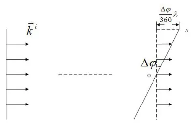
Before the specific test, we adjust the two-dimension scanning frame to a perfect angle to ensure the test accuracy. The maximum permissible errors of luffing angle are shown in Figure 3.
As shown in Figure 3, the quasi-plane wave of CATR reflector antenna can accurately irradiate onto the scanning plane of the two-dimension scanning frame. When we adjust the position of the two-dimension scanning frame, the phase difference between A and O is Δϕ(A is the endpoint of plane wave field, and O is the center point). According to the technical data of CATR reflector, the max CATR plane wave quiet area is about 400 mm∗400 mm, and the distance between A and O is 200 mm. So we can calculate Δθ(Δθ is minimum angle of the turntable adjustment.)
sin Δθ= Δϕ 360λ
1
200 (6)
thus,
Δθ= arcsin Δϕ
360λ
200 (7)
In Eqs. (6) and (7), the unit of parameter λis mm. Because the phase difference is limited to less than±22.5◦, we can calculate from Eq. (7)
Δθ= arcsin 22.5
360 ×1
200 = 0.018
◦ (8)
Because of this limit of 0.018◦ precision, we change the manual equipment into the auto two-dimension turntable adjustment whose angle precision is 0.01◦. The turntable adjustment accuracy now can meet the minimum accuracy range of CATR receiving end in 0.3 THz.
Due to plane wave’s amplitude consistency at the equal phase plane, the turntable adjustment of horizontal azimuth angle θand pitch angle ϕshould be the same. We let θ=ϕ= 0.01◦.
Thinking about the impact of the amplitude difference on deflection angle, we calculate from the path loss empirical formula in free space of electromagnetic wave propagation
Transmission loss (dB) = 32.44 + 20 logL(m) + 20 logf(GHz) (9)
(L is for transmission path, and f is for the testing frequency). In the process of the adjustment of scanning frame at receiving end, the amplitude difference ΔL betweenL1 and L2 is as follows:
(L1 = 3 m, L2 = L1 ±x, sinϕ = 0.x25). What we can know from the equation is that if the requirements of amplitude difference are same in different frequencies, thenϕis independent of frequency and wavelength.
When the amplitude difference is limited to±1 dB
20 logL1−20 logL2 =±1 (11)
thus,
x= 0.366 m (12)
Obviously, when the amplitude difference is limited to±3 dB, parameter xmust be a much larger number.
From the above results we find that the amplitude difference has no constraints on the adjustment angle of scanning frame, so ϕ can only follow the accuracy requirements of phase difference. Because of the high test frequency, we should also consider the influence introduced by the metal and absorbing materials. There are 3 parts in the model of receiving end.
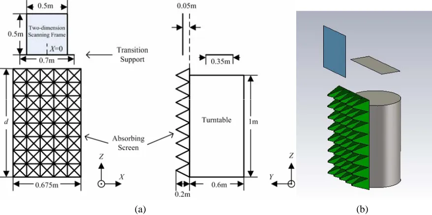
(1) The turntable is a metal cylinder whose diameter is 0.6 m, and the height is 1 m. It is fully covered by the absorbing material.
(2) The transition support between turntable and the two-dimension scanning frame is a metal plate whose length is 0.7 m, and the width is 0.35 m. Because the cylinder is relatively thin, and its radius is several millimeters, it can hardly affect the results and can be ignored.
(3) The absorbing screen uses a spongy wedge form whose length is 0.2 m, and the wedge space is 0.135 m. We observe the electric field distribution in 0.5 m∗0.5 m above the bracket.
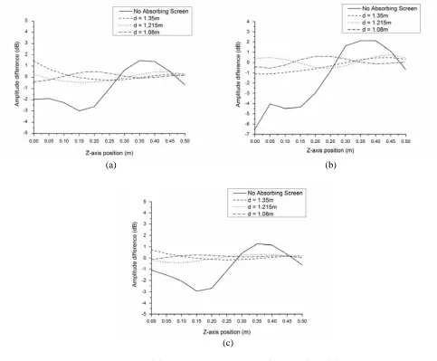
The receiving module is placed on the supporting platform of the two-dimension scanning frame. And we put the receiving antenna 0.05 m in front of the absorbing screen. The simulation model is shown in Figure 4, and the simulation results are shown in Figure 5.
It is not difficult to find that when the absorbing screen is 1.08 m and 1.215 m, the amplitude difference is less than±1 dB, and we can get better results when the height is 1.08 m.
When we aimed at the standard deviation, it was 0.857 dB as the scanning frame was−0.2 m outside the center point. And it is 0.387 dB when the scanning frame is 0.2 m outside the center. Moreover, the center standard deviation is 1.204 dB, and the phase difference is limited to±4.5◦, as shown in Figure 6.
From the above simulation results we can see,
(1) The amplitude difference at the bottom of the scanning plane is relatively larger than that at the top of the scanning plane.
(a) (b)
(a) (b)
(c)
Figure 5. Simulation results. (a) Amplitude difference (X = 0). (b) Amplitude difference (X =−0.2 m). (c) Amplitude difference (X= 0.2 m).
(2) It is necessary to set up the absorbing screen before the metal turntable, and it is better to set a little higher than the metal turntable.
According to the above simulation and calculation, the application limitations of our single reflector CATR system are as follows,
(1) The distance between the CATR reflector and the receiving antenna is 3 m.
(2) The support base of reflector is covered with absorbing material, and the height of the absorbing material is 1.08 m in the environment described above. And it is necessary to recalculate the height if the system is placed in different environments.
4. TESTING OF THE CATR PLANE WAVE AREA
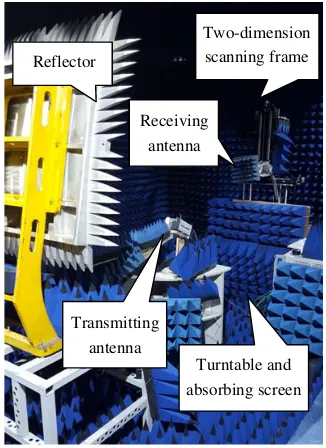
Based on the analysis of the previous section, we can determine our 0.3 THz CATR system, and the structure is shown in Figure 7.
Figure 6. Phase difference fordis 1.08 m.
Reflector
Two-dimension scanning frame
Receiving antenna
Transmitting antenna
Turntable and absorbing screen
Figure 7. 0.3 THz CATR test system.
(a) (b)
Figure 8. The center point’s amplitude and phase testing results of the best receiving turntable position in 0.3 THz. (a) With electronically controlled two-dimension turntable whose accuracy is 0.01◦. (b) Without turntable.
recording the S21 amplitude and phase information of each stroke by the vector network analyser, we can finally determine the plane wave field.
We adjust the pitch angle of receiving turntable to make the receiving plane in the best position.Then we use the scanning frame to scan from top to bottom of theX =−0.25 m axis, observing and recording the amplitude and phase difference of pitch dimension. The frequency is 0.3 THz, and the results are shown in Figure 8(a). Next, we use the scanning frame to scan from left to right of the
Y = 0.25 m axis. The results are shown in Figure 8(b).
In consideration of the requirements of 0.3 THz plane wave field, the plane wave area where the amplitude difference is less than±3 dB and the phase difference less than±22.5◦ is 0.2∗0.2 m.
5. CONCLUSIONS
In this paper, we give the design scheme of a single reflector CATR system and then determin its plane wave area in 0.3 THz. We set the distance between the CATR reflector and the receiving antenna’s aperture plane to 3 m, and the plane wave area is detected to be 0.2 m∗0.2 m. The test results show that this THz band plane wave area can be detected. Moreover, we can do further research on the radiation characteristics of antenna and even the RCS detection of large calibration objects in THz band based on this system. In particular, the THz CATR system is very convenient for the study of electromagnetic scattering characteristics.
REFERENCES
1. Caorsi, S., M. Donelli, A. Lommi, and A. Massa, “Location and imaging of two-dimensional scatterers by using a particle swarm algorithm,” Journal of Electromagnetic Waves and Applications, Vol. 18, No. 4, 481–494, 2004.
2. Donelli, M., I. J. Craddock, D. Gibbins, and M. Sarafianou, “A three-dimensional time domain microwave imaging method for breast cancer detection based on an evolutionary algorithm,” Progress In Electromagnetics Research M, Vol. 18, 179–195, 2011.
3. Rocca, P., M. Donelli, G. L. Gragnani, and A. Massa, “Iterative multi-resolution retrieval of non-measurable equivalent currents for the imaging of dielectric objects,” Inverse Problems, Vol. 25, No. 5, 2009.
4. Franceschini, G., M. Donelli, R. Azaro, and A. Massa, “Inversion of phaseless total field data using a two-step strategy based on the iterative multiscaling approach,”IEEE Transactions on Geoscience and Remote Sensing, Vol. 44, No. 12, 3527–3539, December 2006.
5. Chung, B. K., H. T. Chuah, and J. W. Bredow, “A microwave anechoic chamber for radar-cross section measurement,” IEEE Antennas and Propagation Magazine, Vol. 39, No. 3, 21–26, 1997. 6. Johnson, R. C., H. A. Ecker, and R. A. Moore, “Compact range techniques and measurements,”
IEEE Transactions on Antennas and Propagation, Vol. 17, No. 2, 568–576, 1969.
7. Kou, Y., X. Wang, and C. Liu, “Quiet area tests of a Ka-band compact range,” International Conference on Information Sciences, Machinery, Materials and Energy, 2015.
8. Trunov, V. and A. Kalinin, “On the use of the multifrequency method for studying scattered fields during the antenna measurements in an anechoic chamber,”Radiophysics and Quantum Electronics, Vol. 47, No. 12, 955–965, 2004.
9. Dou, W.-B., H. F. Meng, B. Nie, Z.-X. Wang, and F. Yang, “Scanning antenna at THz band based on quasi-optical techniques,”Progress In Electromagnetics Research, Vol. 108, 343–359, 2010. 10. Hirvonen, T., J. P. S. Ala-Laurinaho, J. Tuovinen, et al., “A compact antenna test range based on
a hologram,”IEEE Transactions on Antennas and Propagation, Vol. 45, No. 5, 1270–1276, 1997. 11. Descardeci, J. R. and C. G. Parini, “Trireflector compact antenna test range,” IEE Proceedings —
Microwaves Antennas and Propagation, Vol. 144, No. 2, 305–310, 1997.