An Efficient Method for Computing the Interaction of Open Ended
Circular Waveguide with a Layered Media
Parul Mathur1, *, Dhanesh G. Kurup1, Mauricio D. Perez2, Syaiful Redzwan Mohd Shah2, Jacob Velander2, and Robin Augustine2
Abstract—This article presents a new method for studying the near-field electromagnetic interaction between a dielectric filled open ended circular waveguide (OECW) and a layered dielectric structure. The proposed model is based on plane wave spectrum theory using a novel and computationally efficient two step integration method. The first integral, involving multiple singularities in the integration path, is efficiently solved using a deformed elliptical integration path which encircles the singularities of the integral. The infinite domain tail integral involving the slowly converging integrand is further solved using an efficient trigonometric transformation. The proposed OECW based method is capable of determining the unknown material properties of any layered dielectric medium, and hence finds application in nondestructive evaluation of materials.
1. INTRODUCTION
Several recent developments in non-destructive evaluation and testing of material illustrate the usefulness of microwaves sensors in applications such as, material characterization, defect monitoring, bone mineral density analysis and food quality monitoring. Compared to other nondestructive testing methods such as radiography and ultrasonics, microwaves based sensors offer increased penetration, increased resolution and low cost [1–4]. The most commonly used waveguide sensors for noninvasive evaluation of materials are open ended coaxial line (OECL) and open ended rectangular waveguide (OERW). OERW based probes have more structural robustness than OECL, and OERW also offers more coupling than OECL due to large aperture size [3]. On the other hand, open ended circular waveguide (OECW) offers an extra orthogonal field component, compared to OERW, thereby, providing more interaction of fields on inhomogeneous materials without the expense of structural robustness [4]. However, analysis of OECW is more challenging than both OECL and OERW.
Different mathematical models with varying levels of computational complexity have been introduced in the literature for finding the near-field electromagnetic interaction between the sensor and layered medium [5–7]. Besson et al. [5] presented a computationally complex integral equation based on dyadic Green’s function for finding relative permittivity from reflection of OECW for material characterization. Bailey and Swift [6] used a complex integral transform method to calculate the input admittance of an air filled circular waveguide covered with dielectric slab. Rudduck and Yu [7] extended the method in [6] for calculating the reflection coefficient, and thereby complex dielectric constant of the external medium using plane wave spectrum theory which essentially yields a challenging infinite domain integral over multiple singularities. However, the method described in [7] has not received much
Received 16 February 2018, Accepted 17 May 2018, Scheduled 27 May 2018
* Corresponding author: Parul Mathur (p [email protected]).
1 Department of Electronics and Communication Engineering, Amrita School of Engineering, Amrita Vishwa Vidyapeetham,
attention due to the computational complexity involved in solving an infinite domain integral over multiple singularities and difficulty in applying the method to material characterization applications.
This article presents a simplified mathematical model for OECW by extending the method in [7] to include dielectric material filling inside the waveguide as well as multiple dielectric layers outside OECW. The proposed approach, based on plane wave spectrum theory, involves a two step integration method consisting of a deformed elliptical integration path to exclude singularities in the integrand and an infinite domain path. The integration method presented in this article is similar to the method in [8], for computing spatial multi-layered Green’s function from spectral domain Green’s function through the infinite domain Sommerfeld integral. The tail integral with upper limit of infinity is solved by converting the integral to a definite integral using a change of variable. Compared to [7], the proposed approach has the capability of easily finding optimum dimensions and dielectric filling material inside OECW for different material characterization applications.
This article is organized as follows. The proposed mathematical model based on plane wave spectrum (PWS) analysis is described in Section 2. Section 3 describes the numerical results obtained for different test cases followed by conclusion in Section 4.
2. THEORY
The proposed analysis of OECW, discussed in this article, assumes that only dominant T E11 mode
is present inside the circular waveguide [7], see Figure 1. According to the plane wave spectrum theory (PWST) [7], the waves outside the waveguide can be decomposed into obliquely incident
T E and T M waves inside the layered media. Assuming that the thickness of layered media is d
with free space backing, see Figure 1, the reflection coefficient S11 at the open ended aperture can
be written as, S11 = YYgg−+YYAA where YA is the aperture admittance, and Yg is the dominant mode
characteristic admittance of circular waveguide. For dominant T E11 mode, Yg can be written as,
Yg =
0c
μ0
1−(x11
ka)2 where c is the dielectric constant of the lossless material filling inside the
waveguide, athe radius of circular waveguide, andk the wavenumber inside the waveguide. It is noted for dominantT E11mode andx11= 1.84118 for dominantT E11mode. The aperture admittance depends
not only on the external material properties but also on the polarization of the incident plane wave. Therefore, aperture admittance YA can be decomposed into TE and TM polarized wave admittances,
YA= YT E +YT M. The perpendicular and parallel polarized plane wave admittances at the aperture,
YT E and YT M, can be written as [6, 7],
YT E = M
∞
0
fT E(β)Yin(β)βdβ (1)
(a) (b)
YT M = M
∞
0
fT M(β)Yin(β)
dβ
β (2)
where M = [x22
11−1], fT E(β) = [
J1(kaβ)x211ka x211−(kaβ)2 ]
2, f
T M(β) = [J1(kaβ)]2, Yin(β) = {Y1[YY21++jYjY12tan(tan(kkzz1d)
1d)]}. Y1 and Y2 correspond to the admittances in external dielectric medium and free space respectively, given
by, Y1 = Y0
N12−cβ2 and Y2 = Y0
1−cβ2 for T E mode incidence and Y1 = Y0 N
2 1
√
N12−cβ2 and
Y2=Y0√ 1
1−cβ2, for TM mode incidence, and Y0 is the free space admittance. J1(x) and J
1(x) are the
Bessel function of the first kind and its first derivative;kz1 =k0
N2
1 −cβ2, which represents the axial
wave number of the external dielectric; k0 is the free space propagation constant; N1 is the complex
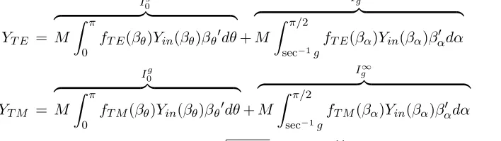
index of refraction of the layer outside the waveguide; β is the angle of incidence [7]. It is noted that the condition|β|>1, which corresponds to the evanescent plane waves [7], needs to be incorporated in Eqs. (1) and (2) for accurate impedance at the aperture. Eqs. (1) and (2) are basically contour integrals along the real axis of complex β plane, see Figure 2, comprising singularities in the region 0≤β ≤g. The proposed method divides the infinite integration domain in Eqs. (1) and (2) into two paths as,
YT E =
I0g
M
π
0
fT E(βθ)Yin(βθ)βθdθ+
Ig∞
M
π/2
sec−1g
fT E(βα)Yin(βα)βαdα (3)
YT M =
I0g
M
π
0
fT M(βθ)Yin(βθ)βθdθ+
Ig∞
M
π/2
sec−1g
fT M(βα)Yin(βα)βαdα (4)
where βθ = 0.5g(1−cos(θ)) +jhsin(θ), g= 1.1
Re(1),h = 10−11ka, and1 is the relative dielectric
constant of external layer. The setting for major axis and minor axis ensures that all the singularities are encircled and yields accurate results. The second tail integration path Re[β] = [g : ∞], although has no singularities, but equally challenging, is solved by changing the integration variableβα = sec(α)
yielding finite upper limit for the integrand. Since both the integrals are transformed into definite integrals, we applied adaptive Gauss-Lobotto quadrature method [9] to yield a numerical solution of the integrals. It is noted that the proposed method enables us to compute near-field electromagnetic field analysis faster than other numerical approaches such as finite element methods (FEM).
Figure 2. Contour of integration in the complex β plane (X represents the singularities of the integrand).
3. NUMERICAL RESULTS
the HFSS simulations, we used an Intel-I7 quadcore computer with 8 GB RAM. We used an OECW of height 35 mm, flange and cylindrical dielectric layer diameter ofλ0, whereλ0is the free space wavelength
and backed with free space for HFSS simulation, see Figure 1.
The OECW was excited through a wave port, and reflection coefficient is measured at the open end of OECW through de-embedding the port. It was noticed that execution time of HFSS solver for a given accuracy constraint depends on mesh settings and drastically increases as the thickness of the external dielectric layer increases. For all our studies, the maximum number of adaptive passes for HFSS is set as 10 with maximum delta error of 0.001 at the solution frequency. We also carried out a detailed sensitivity analysis by filling the waveguide with high dielectric constant and changing the external layer medium properties, for illustrating the generality of the proposed method.
3.1. Lossy Layered Media
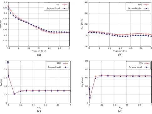
The first example we study is a lossy nonmagnetic biological tissue, whose dielectric properties in 1– 3 GHz range are r = 38 and tanδ = 0.3, as reported in [11]. The waveguide is loaded with lossless
dielectric constant of 30, which is best suited for biomedical applications [12]. The dominant T E11
mode cutoff frequency is 1.6 GHz, and next higher order cutoff frequency starts from 2.1 GHz. Figure 3 shows the magnitude and phase of loaded circular waveguide for fixed thickness and variable frequency as well as fixed frequency and variable thickness. As can be seen in Figure 3, though the model is based on the dominant mode excitation, the magnitude and phase of the reflection coefficient gives excellent
0 0.05 0.1 0.15 0.2 0.25 0.3 0.35 0.4
1.8 2 2.2 2.4 2.6 2.8 3
S11
(mag)
Frequency (GHz)
FEM Proposed Model
100 150 200 250 300
1.8 2 2.2 2.4 2.6 2.8 3
S11
(phase)
Frequency (GHz)
FEM Proposed model
0 0.2 0.4 0.6 0.8 1
0 0.2 0.4 0.6 0.8 1
S11
(mag)
d/λ0
FEM Proposed model
0 50 100 150 200 250
0 0.2 0.4 0.6 0.8 1
S11
(phase)
d/λ0
FEM Proposed model
(a) (b)
(c) (d)
Figure 3. Reflection coefficient of OECW: layer thickness of 0.2λ0, (a) magnitude, (b) phase. Different
agreement with the simulation results for frequencies well above the appearance of next higher order mode as well as varying thickness. Figure 3 also shows that as the thickness of the lossy layer increases, the external layer can be considered as infinite since the reflection coefficient is nearly constant.
In order to study the computational efficiency of the proposed model, we fixed the frequency as 1.9 GHz and vary the thickness of the external dielectric layer. Table 1 shows the computation time of the proposed model and FEM method for varying dielectric thickness. As can be seen in Table 1, as the thickness increases, FEM method takes more time to solve the same problem. For example, the proposed method takes 3 sec for any thickness compared to 9 sec to 11 min 30 sec for FEM method.
Table 1. Comparison of execution time of the proposed method and FEM method.
Thickness (d/λ0)
Execution time (sec) Proposed model FEM
0.2 3 9
1 3 210
1.3 3 316
2 3 690
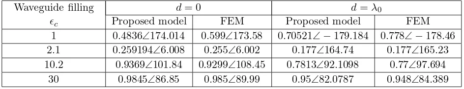
3.2. Waveguide with Different Dielectric Filling
In the next example, we study the effect of filling the waveguide with different materials for fixed radius. The external layered medium is Teflon of varying thickness in the range d= [0 : λ0]. The frequency of
operation is kept midway between the cutoff frequency of dominant T E11 and next higher order mode
for each test case. As can be seen in Table 2, the results obtained using the proposed method has good agreement with FEM based method. The study illustrates that the electromagnetic interaction is more when the dielectric constant of the OECW is comparable with the dielectric constant of the outside layer. Therefore, the results generated in the study can be used to select the filling of the OECW for various applications.
Table 2. Comparison of reflection coefficient for different dielectric material inside and outside the waveguide.
Waveguide filling
c
d= 0 d=λ0
Proposed model FEM Proposed model FEM
1 0.4836∠174.014 0.599∠173.58 0.70521∠−179.184 0.778∠−178.46 2.1 0.259194∠6.008 0.255∠6.002 0.177∠164.74 0.177∠165.23 10.2 0.9369∠101.84 0.9299∠108.45 0.7813∠92.1098 0.77∠97.694
30 0.9845∠86.85 0.985∠89.99 0.95∠82.0787 0.948∠84.389
3.3. External Layer with Different Material Properties
Next, we study the reflection coefficientS11of the circular waveguide of radiusa= 10 mm, withc = 30,
see Figure 1, for different lossless external media with thicknessd=λ0. Figure 4 shows the variation of
complex signalS11 with respect to frequency and different dielectric constant material. As can be seen
-0.2 0 0.2 0.4 0.6 0.8 1
1.8 2 2.2 2.4 2.6 2.8 3 S11
(mag)
Frequency (GHz)
εr=1 εr=5
εr=10 εr=15
εr=20 εr=25
εr=30 εr=35
εr=55
-200 -150 -100 -50 0 50 100 150 200
1.8 2 2.2 2.4 2.6 2.8 3 S11
(phase)
Frequency (GHz)
εr=1 εr=5
εr=10 εr=15
εr=20 εr=25
εr=30 εr=35
εr=55
(a) (b)
Figure 4. Reflection coefficient of OECW for different lossless dielctric materials (a) magnitude, (b) phase.
4. CONCLUSION
A computationally efficient and accurate mathematical model for analyzing the electromagnetic interaction between an open ended circular waveguide (OECW) and an external layered medium is presented. The proposed model is tested for various material constants outside and inside the OECW and shows excellent agreement with a commercial finite element method (FEM) based solver. The study presented in this article, enabled us to derive valuable conclusion on choosing the operating frequency range and material constant inside the OECW for various material characterization applications.
ACKNOWLEDGMENT
This work is financially supported by Indo-Swedish (DST-Vinnova) BDAS project.
REFERENCES
1. Kumar, S. and D. G. Mahto, “Recent trends in industrial and other engineering applications of non destructive testing: A review,” International Journal of Scientific and Engineering Research, Vol. 4, No. 9, 183–195, 2013.
2. Augustine, R., D. G. Kurup, S. Redzwan, P. Mathur, S. Raman, D. Lee, and K. Kim, “Microwave reflectivity analysis of bone mineral density using ultra wide band antenna,” Microwave Optical Technology Letters, Vol. 59, 21–26, 2017.
3. Hyde, M. W. and M. J. Havrilla, “A clamped dual-ridged waveguide measurement system for the broadband, nondestructive characterization of sheet materials,” Radio Science, Vol. 48, No. 5, 628–637, 2013.
4. Ramzi, M. R., M. Abou-Khousa, and I. Prayudi, “Near-field Microwave Imaging Using Open-ended Circular Waveguide Probes,”IEEE Sensors Journal, Vol. 17, No. 8, 2359–2366, 2017.
5. Besson, J. C., S. Mamane, and F. E. Gardiol, “TE11 reflection of open-ended circular waveguides application to nondestructive measurement of materials,” 10th European Microwave Conference, 317–321, Warszawa, Poland, 1980.
6. Bailey, M. C. and C. Swift, “Input admittance of a circular waveguide aperture covered by a dielectric slab,”IEEE Transactions on Antennas and Propagation, Vol. 16, No. 4, 386–391, 1968. 7. Rudduck, R. C. and C. L. Yu, “Circular waveguide method for measuring reflection properties of
8. Yuan, M. and T. K. Sarkar, “Computation of the Sommerfeld integral tails using the matrix pencil method,”IEEE Transactions on Antennas and Propagation, Vol. 54, No. 4, 1358–1362, Apr. 2006. 9. Gander, W. and W. Gautschi, “Adaptive quadrature-revisited,” BIT Numerical Mathematics,
Vol. 40, No. 1, 84–101, 2000.
10. Ansys HFSS (High Frequency Simulation Software) V10 User Guide.
11. Gabriel, C., S. Gabriel, and E. Corthout, “The dielectric properties of biological tissues: I. Literature survey,”Physics in Medicine and Biology, Vol. 41, 2231–2249, 1996.
12. Mathur, P., D. G. Kurup, and R. Augustine, “Design of open ended circular waveguide for non-invasive monitoring of cranial healing in pediatric craniosynostosis,” First IEEE MTT-S