Small Size Active Antenna for VHF Band
Sachin Padalwar
M.E. Student, Dept. of Electronics, AISSMS College of Engineering, Pune, Maharashtra, India
ABSTRACT: In this paper an active antenna is designed at 200 MHz frequency. Active antenna is a combination of a active circuit and passive monopole antenna. Active circuit is consists of an active device, impedance matching and biasing network. This active circuit is used as trans- impedance circuit. Thus an active antenna can be used for VHF (174MHz-216MHz) frequency range applications.
KEYWORDS: Active antenna, VHF, Monopole, biasing network, trans- impedance
I. INTRODUCTION
In the antenna field, there is vast importance for small size antenna which can work over some mega hertz (MHz) frequency. As frequency is inversely proportional to wavelength, designing a small size antenna for low frequency application is difficult. Active antenna overcomes this problem. This active antenna can be used to design at low frequency having a small size antenna.
Active antenna is an antenna which is consists of an active device. This active antenna has peculiar advantages of high SNR, low noise, high gain, and small size integration as compare to the passive antenna. As the antenna size decreases, the resistance of the antenna decreases while reactance increases. This active antenna provides the trans-impedance characteristics by using the active circuit. The active circuit is a active device HEMT, trans-impedance matching and biasing network.
Thus this active antenna is a combination of a passive monopole antenna at the input of the active circuit and having HEMT as an active device. The whole antenna is designed for 200 MHz frequency applications. This antenna can be used as a receiver for various applications such as mobile TV signal reception [1].
II. RELATED WORK
In [1] authors used passive monopole with active circuit for 200 MHz frequency reception. This active antenna is used for mobile TV signal reception. Ick-Jae Yoon, Se-Huan Park and Young- Eil Kim has designed a frequency tunable active antenna for mobile TV signal reception. They have designed a helical antenna which is frequency tunable and with that a matching as well as tuning circuit. This matching and tuning circuit provides the frequency selectivity characteristics and a matching is provided to match the high reactance and low resistance of the small size antenna [2]. Ick-Jae Yoon and Evgeny Balzovsky has designed a small size FET based active antenna for mobile TV signal reception at VHF band. This antenna consist of passive monopole at the input followed by the band pass filter. The active circuit with HEMT as an active device acts as a receiver antenna [5].
Kyeongrae Cho and Songcheol Hong has designed a UHF/VHF/L band low power active antenna for mobile handsets. They used a small passive antenna connected by a multiband LNA. This combination of multiband antenna is connected to the saw filter and receiver circuits. Thus this triple band antenna consist of a passive helical antenna consumes a very less power [4]. Yu Chang Liu and Hong-Yeh Chang has developed an active antenna with the help of voltage controlled oscillator and Yagi antenna for millimeter wave applications. The V band active antenna is designed by using GaAs PHEMT technology and proper gain is achieved at 69.5 GHz frequency [3].
III. ANTENNA DESIGN
• Design Considerations:
• A passive monopole antenna of is used.
• A trans impedance circuit is designed for the input and output impedance. • For the simulation RF spice software is used.
• Thus the active antenna using passive monopole and active circuit designed to receive signal at 200 MHz frequency.
• The active antenna can be tested using Vector Network Analyzer.
• Description of the Antenna Design:
Active antenna is consists of two parts. First part is passive monopole antenna which is a small antenna connected at the input of the active circuit. The second part is active circuit. In this second part a trans-impedance circuit is created using a HEMT transistor ATF55143. The HEMT transistor has high switching time and it can be integrated into a small circuit. It is ideal to work at low frequency of 200 MHz. As the antenna size decreases the resistance of the antenna decreases and the reactance of the antenna increases. The trans-impedance circuit thus matches the highly reactive antenna with the output. The active circuit thus consists of a transistor works as an amplifier.
Figure1: Basic circuit diagram of Active Antenna.
As shown in the above figure, a passive monopole antenna is connected at the input of the active circuit. A HEMT based transistor ATF 55143 from Avago Technologies is used. 3V dc supply is connected as shown in the figure. The trans-impedance circuit is used to provide a match between the antenna and out. The input impedance of the antenna is 5 ohm and 1.5 pf. This impedance is matched to the output 50 ohm. R1, R2 acts as a voltage divider circuit which is to provide proper input switch current to the transistor. Thus an Id current of 3mA is supplied to the transistor. The capacitors C3, C5, C6 and C7 are decoupling capacitors which are used to provide isolation between the Vcc and ground. C8 is used to block DC supply. L2 and L3 are the RF chokes used to restrict AC signal. L1 , C1, C2, C4 and R5 are used for impedance matching.
Table 1: Components list
Components Values
R1 2K ohm
R2 2K ohm
R3 6.8K ohm
R5 90 ohm
C1 1pF
C2 1pF
C3 470pF
C4 1.72pF
C5 1500pF
C6 1500pF
C7 0.1uF
C8 1pF
L1 455nH
L2 292nH
L3 2.2uH
Thus this active antenna is able to receive a signal of 200 MHz frequency and the whole circuit acts as a receiver. For the simulation purpose RF spice software is used. The active antenna can be tested using Vector Network Analyzer.
IV. SIMULATION RESULTS
The simulation studies involve the S parameters study of active circuit as well as the active antenna. The active antenna circuit shown in figure (1) can be simulated using the RF spice software. The RF spice gives us the brief knowledge of antenna gain, return loss, transmission coefficient and reflection coefficient using S parameters. The network analysis test is being performed for the active antenna.
The circuit in figure (1) is implemented in the RF spice software. The network analysis mode is selected from the TEST option. In the network analysis mode connections were given between input and output port. The sweep voltage is maintained between 100MHz to 500MHz. In the output section Cartesian S parameters are selected. As shown in the figure 2, the circuit diagram of figure (1) is implemented in the RF spice software. In this simulation design, ATF 55143 model transistor is chosen which acts as an amplifier. The proposed antenna is fabricated at the drain current of 20mA and 3V bias voltage.
Figure 2: Circuit Design for Simulation Figure 3: Simulation Results.
an amplifier design we should get of more than 0db. From the above results we can conclude that the amplifier design is completely valid at 200MHz frequency.
V. EXPERIMENTAL RESULTS
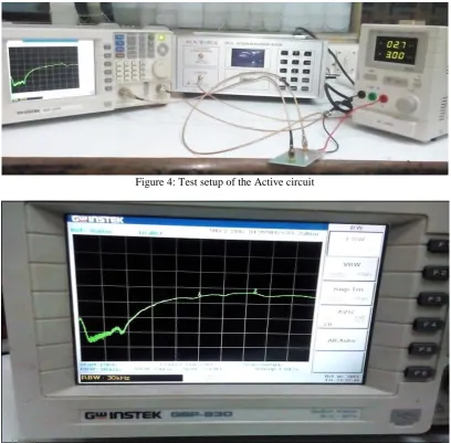
The active antenna can be tested using a spectrum or vector analyzer. We have tested it using spectrum analyzer for the measurement of S21 parameter. As shown in the figure (5), there are two ports, from which antenna port is connected to the tracking generator and second one is output port.
Figure 4: Test setup of the Active circuit
Figure5: Active antenna showing results of -33.2dBm at 206.34 MHz frequency
VI.CONCLUSION AND FUTURE WORK
The simulation and experimental results are matched that is both showed S21 above 15dB. Thus this antenna is capable to receive a signal of 200MHz frequency. Thus various applications which work on the 200 MHz frequency and have to be integrated into a small size can be implemented. In future active antenna for less than 200 MHz frequency can be implemented using the same technique.
REFERENCES
1 Kai Chang, Robert A. York, P.S. Hall, ’Active Integrated Antennas’, IEEE transactions on microwave theory and techniques, vol.50, no.3, March 2002.
2 Yu-Cheng Liu, Hong Ye-Chang, ’Design of V band Active Integrated Antenna with voltage controlled oscillator’, National Central University, Taiwan, 2012.
3 Ick-Jack Yoon, Se-Hyun Park, Young Eil Kim, ’Frequency Tunable Antenna for Mobile TV signal Reception’, Samsung Institute Of Technology, Korea, 2007.
4 Ick Jack Yoon, Evgeny Balzovsky, Se-Hyun Park,’Active Integrated Antennas for Mobile TV signal Reception’, Microwae and optical technology letters, Vol. 49, no.12, 2007.
5 Kyeongrae Cho, Songcheol Hong,’ Design of VHF/UHF/L-Band Low Power Active antenna for Mobile Handsets’, IEEE antennas and wireless propagation letters, vol.11, 2012.
BIOGRAPHY