1
Disk Encryption: Do We Need to Preserve
Length?
Debrup Chakraborty, Cuauhtemoc Mancillas-L ´opez, and Palash Sarkar
Abstract—In the last one-and-a-half decade there has been a lot of activity towards development of cryptographic techniques for disk encryption. It has been almost canonised that an encryption scheme suitable for the application of disk encryption must be length preserving, i.e., it rules out the use of schemes like authenticated encryption where an authentication tag is also produced as a part of the ciphertext resulting in ciphertexts being longer than the corresponding plaintexts. The notion of a tweakable enciphering scheme (TES) has been formalised as the appropriate primitive for disk encryption and it has been argued that they provide the maximum security possible for a tag-less scheme. On the other hand, TESs are less efficient than some existing authenticated encryption schemes. Also TES cannot provide true authentication as they do not have authentication tags. In this paper, we analyze the possibility of the use of encryption schemes where length expansion is produced for the purpose of disk encryption. On the negative side, we argue that nonce based authenticated encryption schemes are not appropriate for this application. On the positive side, we demonstrate that deterministic authenticated encryption (DAE) schemes may have more advantages than disadvantages compared to a TES when used for disk encryption. Finally, we propose a new deterministic authenticated encryption scheme called BCTR which is suitable for this purpose. We provide the full specification of BCTR, prove its security and also report an efficient implementation in reconfigurable hardware. Our experiments suggests that BCTR performs significantly better than existing TESs and existing DAE schemes.
Index Terms—Disk encryption, Tweakable Enciphering Schemes, Deterministic Authenticated Encryption.
F
1
INTRODUCTION
Security of data stored in bulk storage devices such as hard disks of laptop and desktop computers, USB sticks and SD cards has received a fair bit of attention from the cryptographic community. It has been argued that the best solution to this problem is an encryption scheme where the encryption and decryption algorithms reside in the disk controller. The algorithms would have access to the disk sectors but would have no knowledge about the high-level logical partitions of the disk, such as files and directories, which are maintained by the operating system and/or database management systems. Under this scenario, the disk controller encrypts the data before it writes a sector, and similarly, after reading a sector, the disk controller decrypts it before sending it to the operating system. This type of encryption has been termed in the literature as low-level disk encryptionor in-place disk encryption.
A symmetric key cryptosystem with certain specific properties can serve as a solution to the low-level disk encryption problem. From the usability angle, one par-ticularly important property that has been emphasized is length-preservation, i.e., the string that should be stored on a disk sector must have the same length as
• Debrup Chakraborty is with the Computer Science Department, CINVESTAV-IPN, 2508 Av. IPN, San Pedro Zacatenco, Mexico City 07360, Mexico. Email: [email protected]
• Cuauhtemoc Mancillas-L´opez is with Hubert Curien Laboratory UMR CNRS 5516, Universit´e Jean Monnet, Saint-Etienne, France. Email:[email protected]
• Palash Sarkar is with the Applied Statistics Unit, Indian Statistical Institute, 203 B.T Road, Kolkata 700108, India. Email: [email protected]
that of the plaintext. This requirement rules out the schemes which produces authentication tags or uses other kinds of parameters such as nonces, initialization vectors etcetera. From the security angle, the schemes to be used must be secure against adaptive-chosen plaintext and ciphertext attacks. Informally this implies that no efficient adversary should be able to distinguish ciphertexts from random strings; and should not be able to modify a ciphertext so that it gets decrypted to something meaningful.
The cryptographic primitive called tweakable enci-phering scheme (TES) was introduced in [18] as an appropriate candidate for low level disk encryption. The paper also provided the first TES scheme as a mode of operation of a block cipher. In the last few years, a number of proposals for TES have been proposed (see for example [18], [19], [37], [32]) and there have been studies regarding efficient hardware implementations of the proposed schemes [25].
In this paper, we revisit the requirement of length preservation for disk encryption. We argue that the length preserving property may not be crucial for this application as disk manufacturers can suitably format hard disks to accommodate a possible expansion in the ciphertext. A disk sector in any case has to store more information (such as error correction information) than the user data, so, the suggestion for storing a little extra information arising from encryption requirement may not be a big issue. Our analysis shows that space overhead for storing a longer ciphertext is as little as 0.4%.
up the question of whether there are schemes which offer the same (or more) security guarantee as a TES, but at the same time are more efficient. To this end, we consider two kinds of authenticated encryption, namely (nonce based) authenticated encryption (AE) and deterministic authenticated encryption (DAE).
Using a (nonce based) AE for disk encryption is very attractive. However, we argue that there are significant security and practicability concerns which nullify this option. The other natural candidate is DAE with as-sociated data. We argue that a DAE scheme satisfies the security requirement expected of a disk encryption scheme. Further, it also provides true message authenti-cation unlike that of a TES1. The main gain in using a DAE scheme instead of a TES is in terms of efficiency.
To the best of our knowledge, the possibility of using DAE for disk encryption has not been explored earlier. One possible reason for this may be the fact that the notion of TES and its suitability for disk encryption predates the notion of DAE. The other possible reason is that DAE itself was introduced for a different application which is to solve the so-called key-wrap problem [30]. So, we are suggesting that a later introduced primitive (DAE) is more suitable for solving an earlier introduced problem (disk encryption) than the earlier introduced solution (TES).
We present a new DAE scheme called BCTR which is designed to specifically serve as a low-level disk encryption primitive. The design is based on a com-bination of XOR universal hash function and a block cipher. The hash function uses a very fast polynomial based hashing technique due to Bernstein [4]. The overall design strategy is to hash the contents of the sector and the sector address to produce a tag. This tag is used as an initialization vector (IV) in a counter type mode of a block cipher to perform the actual encryption of the contents of the sector. The ciphertext consists of the encrypted sector and the tag. This approach to the design of DAE follows the conceptual framework outlined in [30]. The idea of combining a XOR universal hash and a block cipher to design a DAE scheme has also been suggested in [20], [21]. Our details, however, are different and results in a faster overall scheme. We note that even though the main target of the new DAE scheme is disk encryption, the scheme itself (actually a slightly generalised version) can also be used for other more typical DAE applications.
The structure of BCTR bears some similarity with a construction named DCM-BRW proposed in [9]. In [9] a variant of the counter mode and a special polynomial hash were used to construct a double ciphertext mode (DCM). A DCM is a special mode which produces two ciphertexts for a single message, its functionality and security are different from that of a DAE. BCTR, though
1. TESs do provide implicit authentication in the sense that if a single bit of a valid ciphertext is changed then it gets decrypted to a random plaintext which can be detected by a high level application which would use the plaintext.
shares the same components of DCM-BRW, its details are quite different from DCM-BRW.
Previous and related works: The primitives TES and DAE are well studied and below we briefly mention the relevant previous works.
The notion of TES as a distinct cryptographic primitive and its application to disk encryption was proposed in [18]. Since then, there has been a long line of research in designing secure and efficient TESs [19], [16], [26], [37], [11], [12], [17], [32]. These have mostly been block cipher modes of operations. Application of stream ciphers to TES design have been proposed in [33], [8]. Compara-tive implementation of different TES on reconfigurable hardware has been carried out in [25], [10], [8].
Some schemes for disk encryption have been stan-dardised by different agencies. Notable among these are EME2 [16] and XCB [27], which have been standardized in IEEE-std 1619.2-2010 [2]. In a recent work, several flaws about XCB have been reported in [7]. A mode of operation called XTS has also been standardised for disk encryption in IEEE-std 1619-2007 [1]. It is well known that XTS is not a TES and there are easy block-level mix-and-match attacks on XTS. This is noted in the standard document itself which consciously overlooks this due to the higher efficiency of XTS compared to known TES designs. More discussions regarding the disk encryption standards can be found in Appendix A.
The notion of DAE was formalised in [30] which also proposed a concrete DAE scheme. At a top level, the basic construction idea for DAE outlined in [30] has been followed in later works [20], [21]. As mentioned above, the works [20], [21] follow the strategy of combining a XOR universal hash function with a block cipher to obtain a DAE scheme. A DAE scheme realised as a mode of operation of a stream cipher has been proposed in [34].
2
BACKGROUND
2.1 Notation
We denote the set of all binary strings by {0,1}∗, and the set of all n-bit strings by {0,1}n. For X, Y ∈ {0,1}∗, X||Y will denote the concatenation of the stringsX and Y, and |X| denotes the length of X in bits. For a non-negative integer i < 2n, binn(i) will denote the n-bit
binary representation of i. By X ← S$ , we will denote the event of choosingX uniformly at random from the finite setS.
An irreducible polynomial of degree n over GF(2) provides a representation of the finite fieldGF(2n). The
elements ofGF(2n)can be considered to be polynomials
over GF(2) of degrees less than n. We shall sometimes view n-bit strings as polynomials of degree less than n with coefficients in GF(2) and as such consider n -bit strings to be elements of GF(2n). If X and Y are
realized by ordinary polynomial multiplication modulo the irreducible polynomial representing the field.
An adversary A is an algorithm which has access to one or more oracles and which outputs either 0 or 1. Oracles are written as superscripts. The notationAO1,O2
denotes an adversary Awhich has access to the oracles O1 and O2 and the notation AO1,O2 ⇒ 1 denotes the
event that the adversaryA outputs the bit 1.
An n-bit block cipher is a function E:K × {0,1}n →
{0,1}n, where K ̸= ∅ is the key space and for any
K∈ K,E(K, .)is a permutation. We writeEK(.)instead
ofE(K, .). Let Perm(n)denote the set of all permutations on{0,1}n. Our security analysis will be in the
informa-tion theoretic setting where a block cipher is modelled as a uniform random permutation, i.e., in the analysis a concrete block cipher will be replaced by π which is chosen uniformly at random from Perm(n).
2.2 Tweakable Enciphering Schemes
A tweakable enciphering scheme is a tuple (K,E,D) where K is the key generation algorithm (which is randomised) and E and Dare deterministic algorithms and can be seen as functionsE,D:K×T ×X → X. Here K ̸=∅andT ̸=∅ are the key space and the tweak space respectively. The message and the cipher spaces are X. We shall write ET
K(.) and DTK(.) instead of E(K, T, .)
and D(K, T, .) respectively. The functions E and D are inverses in the following sense:X =DT
K(Y)if and only
if ET
K(X) =Y.
LetΠΠΠT(X)denote the set of all functionsπππ:T ×X → X where πππ(T, .) is a length preserving permutation. Such a πππ ∈ ΠΠΠT is called a tweak indexed permutation. For a tweakable enciphering scheme E : K × T × X → X, we define the advantage an adversary A has in distin-guishingEand its inverse from a random tweak indexed permutation and its inverse in the following manner.
Adv±Eprpf(A) =Pr [
K← K$ :AEK,E−K1 ⇒1
]
−Pr [
π π
π←$ ΠΠΠT(M) :Aπ,πππππ−1⇒1].(1)
A has the following restrictions while querying its or-acles: Let T, P and C represent tweak, plaintext and ciphertext respectively. We assume that an adversary never repeats a query, i.e., it does not ask the encryption oracle with a particular value of(T, P)or the decryption oracle with a particular value of(T, C)more than once. Furthermore, an adversary never queries its decryption oracle with (T, C) if it got C in response to an encrypt query(T, P)for someP. Similarly, the adversary never queries its encryption oracle with (T, P) if it got P as a response to a decryption query of (T, C)for some C. These queries are calledpointlessas the adversary knows what it would get as responses for such queries.
The resource bounded advantageAdv±Eprpf(q, σ)is de-fined to be the maximum advantage over all adversaries A, when A is allowed to make a total of at most q
queries with query complexityσ. The number of queries includes both encryption and decryption queries and the query complexity counts the total number of bits in both encryption and decryption queries.
2.3 Deterministic Authenticated Encryption
Deterministic authenticated encryption (DAE) schemes are encryption schemes which provide security both in terms of privacy and authentication. These schemes were first proposed by Rogaway and Shrimpton [30], where the authors described the syntax of the DAE along with the security definition and a generic construction which they called as the Synthetic Initialization Vector (SIV) mode.
A DAE is a tupleΨ = (K,E,D), where K is the key generation algorithm (which is randomised); E and D
are deterministic algorithms called as encryption and decryption algorithms respectively.
With a DAEΨare associated non-empty setsK,X,Y and H which are respectively the key, message, cipher and header spaces. The encryption algorithmEtakes as input an element fromK×H×X and returns an element inY; the decryption algorithm takes as input an element from K × H × Y and returns either an element in X or a special symbol⊥. We shall writeEH
K(X)orEK(H, X)
to denote E(K, H, X). Similarly, we shall write DH K(Y)
orDK(H, Y)to denote D(K, H, Y).
The message space and the cipher space are non-empty sets containing binary strings, i.e.,X,Y ⊆ {0,1}∗, and the header spaceHcontains vectors whose compo-nents are binary strings. It is required thatDH
K(Y) =X
if EHK(X) = Y and DHK(Y) = ⊥if no such H ∈ H and X ∈ X exist such that EHK(X) =Y.
It is assumed that for any K ∈ K, X ∈ X and H ∈ H, |EHK(X)| = |X|+e(X, H), where e : X × H → N is called the expansion function of the DAE scheme. The valueλ= minX∈X,H∈H{e(X, H)} is called the stretch of
the DAE scheme. In most (possibly all) constructions the amount of expansion is independent of the length of the message.
Let Ψ = (K,E,D) be a DAE scheme. Let A be an adversary attacking Ψ. The adversary has access to the oracleO.Ocan either beEK(., .), whereKis generated
uniformly at random from the key spaceK or it can be $(., .) which returns random strings of length equal to the length of the ciphertext. The adversary can query the oracle with a query of the form (H, M), where H, M denotes the header and message respectively and and thus get back the responses from the oracle. Ahas the restriction that it cannot repeat a query. The privacy advantage of adversaryAis defined as
Advdae-privΨ (A) =Pr [
K← K$ :AEK⇒1
]
−Pr [
A$⇒1].
(2)
queries it with plaintexts of his choice and obtains the corresponding ciphertexts. Finally, A outputs a forgery, which consists of a header and a ciphertext (T,C). A is said to be successful if DK(T,C) ̸= ⊥. For querying
the encryption oracle A follows the same restriction that the adversary does not repeat a query additionally A cannot output (T,C) as a forgery if he obtained C as a response for his query (T, X) to the encryption oracle. The last restriction is to rule out trivial win. The authentication advantage of the adversary Ais defined as the probability that A does a successful forgery, in other words
Advdae-authΨ (A) = Pr[AEK(.,.,.) forges]. (3)
The resource bounded advantages Advdae-privΨ (q, σ) and Advdae-authΨ (q, σ) are defined in the same way as that forAdv±Eprpf(q, σ). In [30] the two notions of privacy and authentication as depicted in equations (2) and (3) were combined to give a unified security definition. In [30] it was shown that the unified definition of se-curity is equivalent to the separate notions of privacy and authenticity. In the present case we use the separate definitions of privacy and authenticity, as that makes it easier to understand the proofs.
2.4 (Nonce Based) Authenticated Encryption
The notion of nonce-based AE predates the formalisation of DAE. As evident, nonce based AE schemes receives as input a nonce in addition to the plaintext and the header. The nonce is supposed to be unique for each message, and no security is guaranteed if the same nonce is ever used to encrypt two messages. The use of a nonce allows more efficient constructions of AE compared to DAE. There are very efficient constructions of nonce based AEs already available in the literature, for example the OCB mode of operation and its variants [29], [28], [22]. The CAESER competition [6] is currently considering more than 50 different AE constructions. All these candidates are not necessarily nonce based AEs.
The security of AE schemes was first formalized in [3]. The currently accepted security definition for nonce based AEs is similar to that of a DAE, i.e., an AE is considered to be secure if it is secure both in terms of privacy and authentication as mentioned in equations (2) and (3). The important difference is that an adversary is allowed to choose the nonce along with the message and headers in its encryption queries and is not allowed to repeat a nonce in its encryption queries.
3
TO
TAG OR NOT TO
TAG?
Suppose that for disk encryption, we wish to use a length increasing encryption primitive where ciphertexts are longer than plaintexts due to the generation of a tag. We will assume that the length of the ciphertext for a message of lengthℓisℓ+λbits, whereλis a constant, i.e.,
it does not depend onℓand is fixed for the scheme. Most (possibly all) practical schemes providing authentication satisfy this condition.
The first question one has to consider is how would such a primitive fit into the existing architecture. There are two options that one may consider. For the ensuing discussion, suppose that disk sectors aresbits long. Application-oblivious strategy:In a typical architecture, software applications such as operating systems and databases read and write data from the disk in chunks ofs-bit blocks. The same continues to be true even with the use of a tag-based disk encryption scheme. To enable this, the disk would have to be organised so that λ addtional bits are made available per sector to store the tag. With this option, the applications do not require any change and continue to read and write data as before. Application-aware strategy: In this option, the organi-sation of the disk is not changed. Instead, the λ-bit tag is stored within the s bits of each sector. As a result, applications will be required to read and write data in chunks ofs−λbits.
Both the strategies require storing the tag and will result in the loss of some amount of available disk space. There are, however, several important differences between the two strategies.
For the application-aware strategy there are several objections. For one thing, it will require basic changes in the input/output routines of a large number of appli-cations such as operating systems and database man-agement systems. This makes the option unattractive from an application point of view. From a more abstract level, this strategy violates the principle of low-level disk encryption.
The deployment of a disk encryption scheme should be invisible to top level applications which should work the same way for both encrypted and unencrypted disks. Modifying the disk read/write modules of applications to enable these to communicate with encrypted disks will make them unsuitable for communicating with un-encrypted disks. Since it is not envisaged that all disks will be encrypted, applications will be required to have two sets of disk read/write modules, one for accessing encrypted disks and another for accessing unencrypted disks. This is clearly a problematic scenario and will result in the whole idea being a non-starter. Having said this, we do remark that there could be some specific niche applications where this approach would be suit-able. The particular tag-based disk encryption scheme that we propose can be suitably modified to handle such situations.
is transparent to the applications.
The application-oblivious strategy requires disk man-ufactures to incorporate certain changes in the way disks are organised. Currently disk sectors are 4096 bytes, which means that each sector can store 4096 bytes of user data. This, however, does not mean that only 4096 bytes are alloted for a sector. The following additional overhead have to be incurred per sector.
Error correction coding:The user data is not stored in the format provided by an application to the disk. An important transformation that the user data un-dergoes is error correction coding and this obviously creates an expansion in length of the original data. So the 4096 bytes of data which an application sends to the disk controller for writing occupies more than 4096 bytes in the physical disk as it is appropriately coded for error correction by the disk controller. Preamble: These bits are used to synchronize read/write head movements. Formatting a disk is writing all preambles on it.
Inter-sector gap: A certain amount of physical gap is kept between two sectors on a disk.
The sum-total of the above constitutes the data sector level overhead. Additionally, there is another overhead which is at the servo sector level. Some idea about the overheads can be found in [36]. A letter by Fujitsu Cor-poration in 2003 declared that the then format overhead of their commercial hard disks were approximately 15% of the sector size, and in the letter it was predicted that maintaining hard disks which store 512 bytes (the sector size in 2003) of user data per sector would make the format overhead to grow to 30% within 2006 [14](Page 15). Current disks store 4096 bytes of user data per sector. The essence of the above discussion is that physically a disk sector is larger than the amount of user data it can store. It is in this context that we put forward the suggestion that disk manufacturers can organise sectors to accommodate an additional λ bits to store a tag. In the application oblivious strategy, theseλbits will not be visible to the applications which access the disks which will continue to read/write data in the same manner as it does for unencrypted disks. If λ = 128 (i.e., 128-bit tags are used for authentication), then the storage overhead incurred due to the storage of the tags is 0.4%. Using smaller values of λreduces the overhead further. Compared to the overhead for error correction coding this is negligible.
It is to be noted that TES based disk encryption schemes do not have any ciphertext expansion. As a result, using a TES for disk encryption does not require any reorganisation of the physical sector layout of a disk. Arguably, it is for this reason that TESs have been proposed as the ideal solution for disk encryption.
Implementing any disk encryption scheme as part of the disk controller entails a performance penalty. It is desirable to minimise this penalty to the extent possible. In this context, the question arises as to whether it is possible to design a disk encryption scheme which is
faster than a TES and provides the same (or better) security guarantee? In the rest of the work we answer this question in the affirmative, but with the trade-off that the physical sector organisation should be capable of storing an additional tag and so incurring a small overhead.
4
TAG-BASED
ENCRYPTION
SCHEMES:
WHICH
ONE TO
USE?
The literature describes two types of symmetric encryp-tion schemes which lead to ciphertexts being longer than plaintext due to the generation of a tag. These are authenticated encryption with associated data and de-terministic authenticated encryption also with associated data.
As already discussed in Section 2.4, AE schemes pro-vide security both in terms of privacy and authentica-tion. The ciphertext produced by these schemes includes an authentication tag, and this authentication tag can be used to verify the authenticity of the ciphertext. There have been many proposals for AE scheme. Among them, some (such as the famous OCB mode of operation [29], [28], [22]) are very efficient and require little computation other than a block-cipher call per block of message.
AE schemes are nonce based, i.e., they require a quan-tity called nonce, which is non-repeating. In other words, to ensure security, each plaintext needs to be encrypted with a different value of the nonce. If the same value of the nonce is used for two encryptions then the scheme loses security. It is in the generation and management of nonces that problems arise. We next discuss the problems of using a nonce based scheme for disk encryption.
4.1 Problems with Nonces
AE requires nonces for both encryption and decryption. Thus, in a ciphertext produced by an AE scheme, the nonce has to be stored along with the ciphertext. This results in further increasing the sector level overhead beyond what would be required for storing only the tag. If a scheme uses a µ-bit nonce and a λ-bit tag, the expansion would beµ+λbits beyond the user data. It is possible to consider several strategies for generation and storage of nonces. We list these possibilities and analyse them:
gets encrypted with a unique nonce. Also, storing the 40-bit counter would be sufficient as the sector addresses are implicitly known by the disk controller.
A serious security concern with this strategy is that a malicious adversary may be able to tamper the value of the counter stored in a sector and force the encryption of two different messages with the same nonce. This is possible in the following scenario. The adversary sends a plaintext to be stored in a sector and the disk controller generates the ciphertext and stores the current counter value and the ciphertext on the disk. The adversary reads off the ciphertext and tampers the data stored on the sector by decrementing the value of the counter. It then sends another plaintext to be stored in the same sector. In response, the disk controller reads the current counter value stored in the sector, increments it and encrypts the provided plaintext with the counter value and again stores on the sector. By reading off the new ciphertext, the adversary is able to obtain the ciphertexts corre-sponding to two different plaintexts encrypted under the same nonce. This violates the security requirement of nonce-based encryption schemes and can lead to concrete attacks.
Apart from the security issue, storing the counter along on the sector creates another inefficiency. Suppose a write to the sector is required. To determine the present value of the counter, the disk controller must first read the entire sector before it can encrypt the given data and write back. So, each write request necessarily generates a read request.
A solution would be to not store the counter value in the sector but, to maintain a separate counter for each sector in additional tamper resistant storage, which may be a part of the disk controller. Given the huge number of sectors that are present in modern day disks, such a solution is infeasible from an engineering point of view. Global counter:In this approach, a single global counter is maintained in a tamper resistant storage for the whole disk and any sector write uses the current value of the counter and increments it. To enable decryption, the value of the counter under which encryption is done has to be stored in the sector along with the ciphertext. One major difficulty with this solution is the following. Suppose several sectors are required to be written simultaneously. With a single global counter this will not be possible. Since unique counter values will be required, the writes will necessarily have to be done in a sequential manner. This will result in significant performance degradation.
An intermediate solution can be to use several global counters. While this is an engineering compromise be-tween a single global counter and sector level counter, it still has the problem that the global counters have to be stored in tamper resistant memory. To avoid repetition, the nonces for a particular sector must be from a single counter. So, the sectors in a disk would have to be partitioned and each counter is to be used for servicing one set of sectors. As a result, the problem of
simultane-ous writing of sectors in one particular partition is not resolved.
Random Nonce:Nonces are required to be distinct, but if relatively long nonces are used, then one may work with a random nonce. For example, if 128-bit nonces are used, then using a random nonce will with high probability ensure that the first264 nonces are distinct. Such nonces
would have to stored in the sector along with the cipher-text. The major problem with this approach is the proper generation of random nonces for each sector write. It is this problem which makes this solution infeasible.
In summary, the issue of secure generation, handling, and storage of nonces is a non-trivial engineering task and effectively rules out the use of nonce based AE schemes for disk encryption.
5
USE OF
DAE SCHEMES FOR
DISK
ENCRYP-TION
DAE schemes are similar to AE schemes but they do not require nonces. They provide almost the same security as that of AE schemes. The only difference is that DAE schemes being deterministic produce the same ciphertext if the same plaintext is encrypted multiple times.
We propose the use of DAE schemes with support for authenticating associated data as a solution to the disk encryption problem. The proposed usage is as follows.
Plaintexts are of fixed lengths which is the length of the user data that is stored on individual sectors. For encryption, the sector address is used as the associated data. The ciphertext consists of two strings, one of which is of the same length as the plaintext and the other string is a short fixed length tag. The first string is written on the portion of the sector which stores user data. The tag is written in an additional space in the sector. As argued above, this is the application oblivious strategy and the physical disk structure has to be organised to provide space for storing such a tag.
In the following subsections we discuss several issues regarding the suitability of DAE when used in the above manner.
5.1 Is Security of DAE Adequate for Disk Encryp-tion?
Both DAE and TES being deterministic schemes, they share a common feature. If the same plaintext is en-crypted with the same tweak (associated data) twice then the ciphertexts are also the same. We would like to suggest the replacement of TES with DAE. For this we need to argue that the security guarantee of a DAE scheme is not at a lower level than the security guarantee of a TES.
encryption and decryption algorithms of the TES instan-tiated with a uniform random key) or random (i.e., the oracles are two independent random oracles).
Security of DAE can also be viewed in a similar manner. The adversary is given access to two oracles (say left and right) which it can query in an adaptive manner. At the end, it has to determine whether the oracles are real or random. For the real case, the left and the right oracles are respectively the encryption and the decryption algorithms of the DAE scheme instantiated with a uniform random key; while for the random case, the left oracle is a random oracle which returns independent and uniform random strings of appropriate length and the right oracle is one which always returns ⊥.
The security of DAE defined earlier implies security against the above adversarial model. This can be easily seen by considering a sequence of three games. In the first game, the oracles provided to the adversary are real. In the second game, the decryption (i.e., the right) oracle is replaced by an oracle which always returns ⊥. The advantage of an adversary to distinguish be-tween these two games can be upper bounded by the advantage of an adversary in defeating the authenticity of the DAE scheme. In the third game, the encryption (i.e., the left) oracle is replaced by a random oracle which returns independent uniform random strings of appropriate lengths. The advantage of an adversary to distinguish between the second and the third game is upper bounded by the advantage of an adversary in defeating the privacy of the DAE scheme.
The first game is the real game and the third game is the random game. For a secure DAE scheme, the difference in an adversary’s advantage in the two games are bounded above by the sum of the advantages of de-feating either privacy or authenticity of the DAE scheme. This informal argument shows that a DAE scheme secure in the model defined in Section 2.3 implies security in the two-oracle model. For a more formal treatment of this approach see [30].
Two-oracle security models for TES and DAE are similar. Both essentially capture the intuition that access to these oracles do not provide sufficient information to the adversary to distinguish real from random. So, from a security point of view, replacing TES with DAE does not entail any loss.
True Authentication: DAE are authenticated encryption schemes and ciphertexts produced by such schemes have authentication tags. Using these tags the authenticity of the ciphertext can be explicitly verified and invalid ciphertexts can be explicitly rejected.
On the other hand, TESs are length preserving and so they cannot provide true authentication. The only guarantee that such schemes can provide is that an adversarially modified ciphertext will get decrypted to a random plaintext. This can be detected by a high level application which uses the data, but the decryption algorithm itself cannot detect this. In some (though rare)
cases, this may cause some difficulty if the plaintext were to be truly random since then there would be no way to detect tampering in the ciphertext. Thus, a TES is unable to provide true authentication. The type of authentication that they provide has been termed as “poor man’s authentication” in [15].
Limitations:It is to be noted that sector-level mix-and-match apply to disk encryption schemes irrespective of whether a TES or a DAE scheme is used. This can be seen as follows. Suppose there are two sectors having addressesadd1andadd2. An adversary makes two
plain-text queries: the first query is to encrypt a stringw1 to
the first sector and a stringw2 to the second sector; the
second query is to encrypt x1 and x2 to the first and
the second sectors respectively. This creates ciphertexts u1 for (add1, w1); u2 for (add2, w2); y1 for (add1, x1);
andy2 for(add2, y2). Possessing(u1, u2)and(y1, y2), the
adversary can now create the ciphertextsu1 for the first
sector and y2 for the second sector. Decryption of this
ciphertext results in the dataw1for the first sector andx2
for the second sector. Since this data was never written to the disk, this defeats the security of the scheme.
Thus, both TES and DAE based disk encryption schemes ensures security only at the granularity level of a sector. Viewed across multiple sectors, neither schemes provide proper security. Having said this, we would like to point out an important difference in the way an adversary would have to carry out the above attack depending on whether TES or DAE is employed. With a TES, the adversary can simply swap the user data portions of the two sectors as mentioned above leading to a successful attack. When a DAE is applied, the tags are written to a portion of the disk which is separate from the user data portion. So, to mount a successful mix-and-match attack, the adversary would be required to access both the user data portions along with the control portions of a sector. To some extent, this makes the attack a little more difficult to mount.
5.2 Gains and Loses
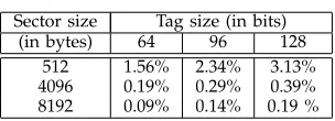
Loss of space:As argued above, it is technically feasible for disk manufacturing companies to modify the physi-cal organisation of a disk to create space for storing the tag produced by a DAE scheme. Needless to say, the extra information stored in form of a tag will mean loss of space for storing user data. A DAE scheme produces a tag of fixed length for each plaintext encrypted. Thus if one fixes the tag length toλbits then for each plaintext of ℓ bits the ciphertext will be (ℓ+λ) bits long. So, greater the length of the plaintext the less would be the percentage loss of space.
TABLE 1 Extra format overhead
Sector size Tag size (in bits) (in bytes) 64 96 128
512 1.56% 2.34% 3.13% 4096 0.19% 0.29% 0.39% 8192 0.09% 0.14% 0.19 %
algorithm more appealing, as due to the greater sector size the total loss incurred in space for storing the tags is lesser. In Table 1 we show the amount of loss in space that would take place taking into account various disk sizes and tag lengths.
Table 1 shows that the extra format overhead for using a DAE with tag length 128 bits would be a negligible 0.4% for 4096-byte sectors. The security promise of a 128-bit tag may not be required. It is quite likely that a 64-bit tag will suffice if the number of times a sector is encrypted or decrypted between two key changes is not too high. For 64-bit tags, the overhead would be 0.2% for 4096-byte sectors.
Gain in efficiency: The current constructions of tweak-able enciphering schemes fall into three basic categories: Encrypt-Mask-Encrypt type, Hash-ECB-Hash type, and Hash-Counter-Hash type. CMC [18], EME [19], and EME∗[16] fall under the Encrypt-Mask-Encrypt group. PEP [11], TET [17], and HEH [31] fall under the Hash-ECB-Hash type; and XCB [26], HCTR [37], HCH [12], HMCH [32] fall under the Hash-Counter-Hash type.
These constructions use a block cipher as the basic primitive, and in addition, some schemes utilize a uni-versal hash function which is a Wegman-Carter type polynomial hash or a more efficient variant known as Bernstein-Rabin-Winograd hash [32]. The constructions of the Hash-Counter-Hash and Hash-Encrypt-Hash type invoke two polynomial hash functions with a layer of encryption in-between. The Encrypt-Mask-Encrypt structure consists of two layers of encryption with a light weight masking layer in-between.
So, the main computational overhead of the Encrypt-Mask-Encrypt architecture is given by the block cipher calls, whereas for the other two classes of constructions, both block cipher calls and finite field multiplications ac-count for a significant portion of the total computational cost.
Known DAE constructions require less computational overhead. This is due to the fact that it is possible to realize a DAE with a single layer of polynomial hashing along with a layer of encryption. In comparison, hash-based TES constructions require two layers of hashing and a layer of encryption. The operation counts of the existing TES and DAE constructions are provided in Tables 2 and 3 respectively.
Usability issues: As mentioned earlier, the best way to go for low level disk encryption is to implement the encryption and decryption algorithms to be a part of the disk controller. Additionally, a mechanism for directly
injecting a key into the disk controller would be required. The resulting architecture would ensure that the disk encryption is transparent to the higher level applications which access the disk. Note that a mechanism for direct key injection is required irrespective of whether a TES or a DAE is used for disk encryption.
The direct key injection into the disk controller can be achieved by having a port in the disk to directly read the key from a small portable device. Such a device can be a small USB drive or an RF device. Design of the key transfer mechanism, however, will require careful security engineering so that the key is not revealed during the transfer. While important, these details are outside the present scope of the work and so we do not consider them any further here.
6
BCTR: A NEW
DAE SCHEME
BCTR uses a special class of polynomial proposed in [4]. These polynomials were later named as Bernstein-Rabin-Winograd (BRW) polynomials in [32]. Let X1, X2, . . . , Xm ∈ GF(2n), and h ∈ GF(2n) then a
BRW polynomial overGF(2n)is defined as follows
• BRWh() = 0
• BRWh(X1) =X1
• BRWh(X1, X2) =X1h⊕X2
• BRWh(X1, X2, X3) = (h⊕X1)(h2⊕X2)⊕X3
• BRWh(X1, X2, . . . , Xm) =BRWh(X1, . . . , Xt−1)(ht⊕
Xt)⊕BRWh(Xt+1, . . . , Xm), if t ∈ {4,8,16,32, . . .}
and t≤m <2t.
Form≥2,BRWh(X1, . . . , Xm)can be computed using
⌊m/2⌋multiplications andlgmsquarings [4], [32]. Thus, it requires half the number of multiplications compared to a normal polynomial.
6.1 The Construction
BCTR is designed to be suitable for low level disk encryption. In particular, the message space of BCTR is {0,1}nm where n is the block length of the underlying
block cipher. Hence a message for BCTR is of fixed length containingmblocks ofn-bits. The tweak space is {0,1}n and the cipher space is{0,1}mn+λwhereλis the
The details of the working of the algorithm are self explanatory as depicted in Figure 1. It essentially consists of a BRW hashing in combination with a modified counter mode which was proposed in [37]. In compari-son to previous works, the main efficiency improvement comes from the application of BRW hashing.
To encrypt a message of m blocks, BCTR requires (m+ 1)block cipher calls. In addition to this it requires ⌊m+1
2 ⌋+ 1 finite field multiplications and computation
of lg(m+ 1) squares. Note that, computing squares in binary fields is much more efficient than multiplication. Thus, the (m+ 1) block cipher calls and the⌊m+1
2 ⌋+ 1
multiplications constitute the main computational over-head of BCTR. Same number of operations are required for decryption.
The construction requires two keys, hthe key for the BRW polynomial and K the block-cipher key. Using known techniques, it is possible to generate the key h using the block-cipher key and still obtain a secure construction, but this would mean one more block-cipher call or a storage of key related material which is (almost) the same as storage of an extra key. So, we decided to keep two independent keys.
As is the case with all DAE schemes, the encryption algorithm requires two passes over the data, one for computing the tag τ and other for generating the ci-phertext. The ciphertext is generated using a counter type mode of operation which is fully parallelizable. For decryption, in practice, two passes are not required. As the counter mode and the computation ofτ can be done in parallel. Thus the construction offers ample flexibility for an efficient parallel implementation. Also, in an op-timized hardware implementation the decryption speed would be significantly better than the encryption speed. For the application of disk encryption, this property can be very useful; as in normal usage, a sector which has been written once is expected to be read multiple times. Handling length variability: Our definition of BCTR assumes that messages are all of the same length which is a multiple of the block length. For the purposes of disk encryption, this is sufficient. More generally, how-ever, there can be applications which require to encrypt variable length messages which are not necessarily a multiple of the block length. There are standard ways to handle such situations and we briefly mention the required modifications.
The main change would be in the application of the BRW map. This would now be applied to a string which is a concatenation of the following three strings: the mes-sage, zero padded to the next multiple ofn; a singlen-bit block encoding the binary representation of the length of the message; and the tweak. Hashing such pre-processed messages will ensure low differential probability in the more general case of variable length messages. The other modification will be to run the counter mode to generate sufficiently many bits required to encrypt the message. Comparison to existing TESs: It has been already dis-cussed in Section 5.2 that the existing TES can be
classi-fied into three basic categories according to the way they are constructed. They are hash-ECB-hash, hash-counter-hash and encrypt-mask-encrypt types. For the first two types (for example TET, HCTR, HCH, XCB etcetera) one uses two layers of polynomial hashes with a layer of ECB or a counter mode in-between. For the last type (example CMC, EME) there are two encryption layers.
To encrypt/decrypt a message/cipher ofmblocks the first two types roughly requiremblock-cipher calls along with2mmultiplications. In [32] some new constructions of hash ECB hash type and hash counter hash type were proposed which uses a BRW polynomial to compute the hash and for these constructions aboutmmultiplications are required. The encrypt-mask-encrypt type algorithms like EME [19] and CMC [18] require about 2m block cipher calls and no multiplication.
In Table 2 we compare the number of operations required for tweakable enciphering schemes for fixed length messages which usesn-bit tweaks with the num-ber of operations required for BCTR. From this table, we can see that encrypting with BCTR will be more efficient than encrypting by the existing tweakable enciphering schemes which uses polynomial hashing. A direct com-parison to CMC/EME is not possible, since this depends on the relative efficiencies of a block cipher call and a multiplication. Later we provide implementation results which indicate that BCTR performs better than encrypt-mix-encrypt type TESs.
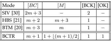
Comparison to existing DAE schemes: Table 3 shows the operation counts of BCTR compared to some of the other known DAE schemes. From this it is clear that BCTR is better than both HBS and BTM. The comparison to SIV is based on the comparative performance of a block cipher call versus that of a multiplication. Our implementation results suggest that multiplication is faster than a block cipher call. For SIV, however, the disadvantage is that the sequential CMAC algorithm is used to perform authentication. As such, there is no good pipelined implementation of SIV and for this reason we later do not report implementation results for SIV.
6.2 Security of BCTR
The following result states the security property of BCTR.
Theorem 1: Let BCTR[Π]denote BCTR as in Figure 2 where the block cipher EK() is replaced by a
permu-tation π ←$ Perm(n). Let A be an arbitrary adversary attacking BCTR[Π]who asks a total ofqqueries, then
Advdae-privBCTR[Π] (A)≤ 9m
2q2
2n , (4)
Advdae-authBCTR[Π] (A)≤ 1 2n +
9m2q2
2n . (5)
Note, that for the authentication bound in equation (5), qincludes the final forgery query of A.
AlgorithmBCTR.ETh,K(P1, . . . , Pm)
1. γ←h·BRWh(P1||P2||. . .||Pm||T)
2. τ ←EK(γ)
3. forj= 1tom
4. Rj←EK(τ⊕binn(j)) 5. Cj←Rj⊕Pj
6. endfor
7. return(C1||C2||. . .||Cm||τ)
AlgorithmBCTR.DTh,K(C1, . . . , Cm, τ)
1. forj= 1tom,
2. Rj←EK(τ⊕binn(j)); 3. Pi←Cj⊕Rj
4. endfor
5. γ←h·BRWh(P1||P2||. . .||Pm||T);
6. τ′←EK(γ)
7. ifτ′=τ return(P1, . . . , Pm)elsereturn⊥;
Fig. 1. Encryption and decryption using BCTR.
TABLE 2
Comparison of BCTR with tweakable enciphering schemes for fixed length messages which usesn-bit tweak. [BC]: Number of block-cipher calls; [M]: Number
of multiplications, [BCK]: Number of blockcipher keys, [OK]: Other keys, including hash keys.
Mode [BC] [M] [BCK] [OK]
CMC [18] 2m+ 1 − 1 −
EME [19] 2m+ 2 − 1 −
XCB [26] m+ 1 2(m+ 3) 3 2
HCTR [37] m (2m+ 1) 1 1
HCHfp [12] m+ 2 2(m−1) 1 1
TET [17] m+ 1 2m 2 3
Constructions
in [32] using m+ 1 2(m−1) 1 1
normal polynomials Constructions
in [32] using m+ 1 2 + 2⌊(m−1)/2⌋ 1 BRW polynomials
BCTR m+ 1 1 +⌊(m+ 1)/2⌋ 1 1
TABLE 3
Comparison between BCTR and DAE schemes for encryptingmblocks of messages. In the DAE schemes
the operation counts are based on only one block of tweak. [BC]: Number of block-cipher calls; [M]: Number
of multiplications, [BCK]: Number of blockcipher keys, [OK]: Other keys, including hash keys.
Mode [BC] [M] [BCK] [OK]
SIV [30] 2m+ 3 − 2 −
HBS [21] m+ 2 m+ 3 1 −
BTM [20] m+ 3 m 1 −
BCTR m+ 1 1 +⌊(m+ 1)/2⌋ 1 1
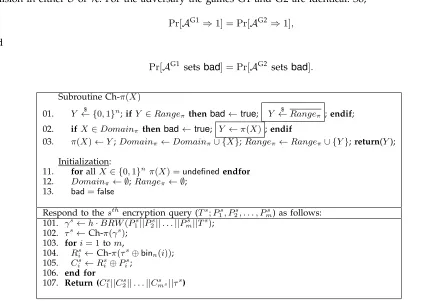
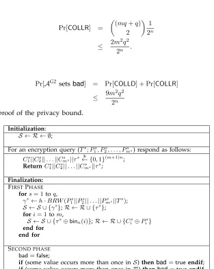
of BCTR when the blockcipher is considered to be a uniform random permutation. The corresponding com-plexity theoretic bounds can be easily derived from the above theorem. We prove Theorem 1 using the standard game playing technique as used in [12], [18], [19], [21]. The complete proof is provided in Appendix B.
7
HARDWARE
IMPLEMENTATION OF
BCTR
In this section we present an optimized hardware archi-tecture of BCTR and provide experimental performance data of the architecture. We also provide performance comparison of BCTR with other feasible architectures for disk encryption.
Counter '
4
Iodd Ieven
Oodd
Oeven odd
even
Fig. 2. Architecture of BCTR-2
7.1 Basic Design Decisions
We develop our architecture keeping in mind high end FPGAs, in particular our target device is Virtex 5 xc5vlx330-2ff1760. The primary goal of the design is to achieve high speed, but we also try to keep the area metric reasonable. We optimize the architecture for message lengths of 4096 bytes. The block cipher is fixed to be the AES with 128-bit key and so the two keys that BCTR receives as input are both 128 bits long.
computation requires computing powers of the hash key h, these are computed on the fly.
The multiplier used to implement the hash is a four-staged pipelined Karatsuba multiplier. The registers were placed after a meticulous re-timing process to create almost balanced pipeline stages. The number of stages were selected to match the frequency of the AES, which is the other significant hardware component of the architecture. It is to be noted that in [10], a three staged pipelined multiplier was used. The BRW hash in [10] was used for the design of the disk encryption modes HMCH and HEH [32]. Both these schemes requires an inverse call to the block cipher for decryption, hence the architectures of these modes include a decryption core of the AES. The specific implementation of the decryption core used there had a much higher critical path compared to the encryption core, and the critical path of the circuit was given by the AES decryption core. Hence in [10], a 3-stage pipelined multiplier was used to match the frequency of the decryption core. In case of BCTR the AES decryption core is not required, hence the main aim was to match the critical path of the hash module with the AES encryption core. This allowed us to use a four staged multiplier.
The AES:The AES is used in BCTR in the counter mode. This allows a pipelined AES implementation. The struc-ture of AES (with 128-bit key) allows a natural 10-stage pipelined implementation, where each round occupies a stage. Our AES design closely follows the techniques used in [5]. In [5], the S-boxes were implemented as 256×8 multiplexers. This was possible due to special six input lookup tables (LUT) available in Virtex 5 devices. One S-box fits into 32 six-input LUTs available in Virtex 5 FPGAs. The design presented in [5] is sequential, we adapt the ideas in [5] to a 10 staged pipelined AES encryption core. Some of our designs involves multiple AES cores, for these designs all AES cores share the same key generation module.
7.2 Proposed Architecture of BCTR
Two architectures were developed, one using two AES cores which we call as BCTR-2 and another using a single AES core which we call as BCTR-1. We will only describe in detail the architecture of BCTR-2, but we will present the results of both architectures in Section 7.3.
A simplified architecture of BCTR-2 using two AES cores is shown in Figure 2. The main components of the architecture are as follows:
1) Two pipelined AES cores labeled AESeven and AESodd, both cores have one input port labeled inAES and one output port labeled outAES. The round keys for both the cores are received from a single round key generator, which is also shown in the figure.
2) The block for computing the BRW polynomial labeled BRW Hash. This component receives the hash key through the input port H, through inA
and inBit receives the data to be hashed. For the specific architecture that is used to compute the BRW polynomial, two data blocks are required si-multaneously to perform the multiplications, hence it receives data through two input ports. The out-put port outH outout-puts the BRW hash. For details of the architecture of this block see [10].
3) A counter labeled Counterwhich has two output ports labelledoddandeventrough which it outputs odd and even values. We will further denote the outputs of these two ports as Counterodd and
Countereven respectively.
4) The multiplexer labeled 1 selects the input of
AESodd between output of BRW Hash, τ ⊕ Counterodd and τ′ ⊕Counterodd. Here τ is the
verification tag generated by encryption and τ′ is the tag to verify the output of decryption which is fed to the architecture as a part of the ciphertext. 5) Multiplexers labeled2and 3are used to select the
correct inputs for BRW Hash for encryption and decryption. For encryption, the multiplexers feed the BRW Hash directly from the data input ports Iodd and Ieven. For decryption it feeds the xor of
the input ports and the outputs of the AES cores, i.e., for decryption it feeds theBRW Hashwith the same values as in the output portsOodd andOeven.
6) Multiplexer 4 serves the same purpose as of mul-tiplexer 1 but it selects inputs forAESeven. 7) The comparator labeledComparatoris used for the
tag verification during decryption. It receives as inputs τ and τ′, and checks if they are equal. The data flow is controlled by a control unit constructed using a finite state machine, which is not shown in the figure. We explain the basic data flow in the architecture separately for encryption and decryption.
For encryption, first the BRW hash is computed using plaintext blocks fed in portsIoddandIevento getγ.
Fur-ther,γis processed by AESodd to produceτ. The value in register τ is presented in port τo as authentication
tag and also is used as an initialization vector in the counter mode.AESodd andAESeven both computeRj
using τ ⊕Counterodd and τ ⊕Countereven as inputs
respectively. The plaintext is fed again in portsIodd and
Ievenand they are xored withRj’s getting the respective
ciphertexts in ports Oodd and Oeven.
For decryption, first the architecture receives the tag to verify inIodd and it is stored in registerτ′ to be used as
IV in the counter mode.AESodd andAESevencompute
Rjusingτ′⊕Counteroddandτ′⊕Counterevenas inputs
respectively. Now the ciphertext in portsIodd and Ieven
are xored with the Rj to get the plaintexts in ports
Oodd and Oeven which are also used as inputs forBRW
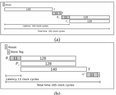
Timing Analysis of BCTR-2: Now we analyze the be-havior of the circuit of BCTR-2 in time. In Figure 3(a) a time diagram for the encryption process is shown, which clearly shows the possible parallelization. For computing the valueγa BRW polynomial on 257 blocks is computed which takes 135 cycles, further this result has to be multiplied by h which takes an additional 4 cycles (as we use a four staged pipelined multiplier), hence the total number of clocks required for producing γ is 140 (this includes an additional cycle for synchronization). We use a pipelined AES whose latency is 11 cycles. When γ is ready it is fed to AES, after 11 clock cycles τ is produced which is stored in the registerτττ which is connected to the output τo. After τ has been generated
then the generation of the stream Rj is started by the
two AES cores simultaneously. The first two blocks of the streamR1is ready after 11 cycles. After this, in each cycle
two cipher blocks are produced. The first valid block of ciphertext appear in the output after a latency of 164 clock cycles. All the ciphertext blocks are produced after 128 clock cycles and hence the complete encryption of a 4096 bytes is achieved after292clock cycles.
(a)
1 Store Tag
Latency 13 clock cycles
Total time 165 clock cycles
(b)
Fig. 3. Timing diagram for BCTR-2: (a) encryption (b) decryption.
In the encryption process the computation ofγcannot be parallelized with the encryption with AES, but this is not the case for decryption. This makes the decryption and verification process very different from the encryp-tion process. The time diagram for decrypencryp-tion process is shown in Figure 3(b). As shown in the diagram, the circuit starts with the computation of the plaintext just after the tag is stored in the register. As soon as two plaintext blocks are available the computation of τ can be started. The first valid block of plaintext is produced after 13 clock cycles. The total process, i.e, decryption and verification is done using only 165 clock cycles which is much less than the encryption process.
Architectures for EME2 and XCB: We compare the performance of our architecture with the architectures of EME2 and XCB, as they are the current standards for
TABLE 4
Summary of the main hardware resources in the architectures of BCTR-1, BCTR-2, EME2 and XCB
Scheme Pipelined AES Pipelined AES Sequential AES Pipelined encryption core decryption core decryption core multiplier
BCTR-1 1 0 0 1
EME2-1 1 1 0 0
XCB-1 1 0 1 1
BCTR-2 2 0 0 1
EME2-2 2 2 0 0
XCB-2 2 0 1 2
disk encryption. For a fair comparison, we developed two architectures for both EME2 and XCB, we call them EME2-1, EME2-2, XCB-1 and XCB-2. The design goal of these architectures were such that EME2-1 and XCB-1 matches the speed of BCTR-1 and EME2-2 and XCB-2 matches the speed of BCTR-2. To achieve this, the architectures require different hardware resources. A summary of the number of main blocks utilized in each architecture is presented in Table 4. We describe in Appendix C some important aspects of the architectures EME2-2 and XCB-2.
7.3 Results
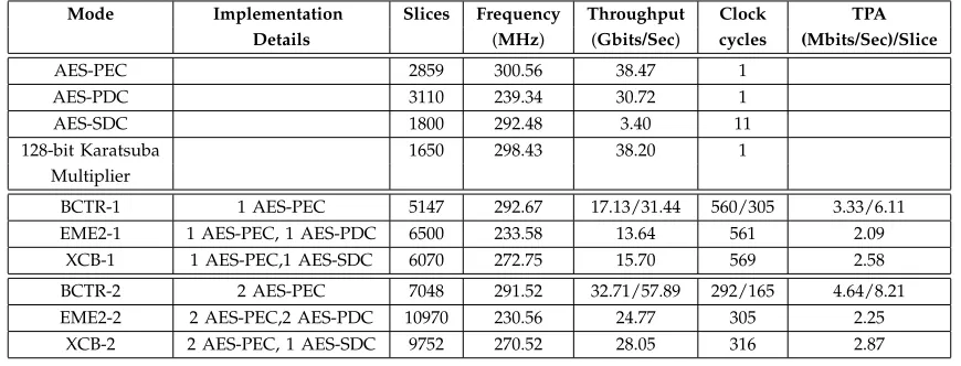
We implemented BCTR-1, BCTR-2, EME2-1, EME2-2, XCB-1 and XCB-2 in Virtex 5 xc5vlx330-2ff1760. The results reported in Table 5 were obtained after place and route simulation using Xilinx ISE 13.4. In Table 5 we compare performance of BCTR with the implemen-tations of EME2 and XCB. The performance is measured in terms of slices, frequency, throughput and throughput per area (TPA). For BCTR-1 and BCTR-2 there are two values specified for throughput, cycles and TPA, these values are for encryption/decryption. For EME2 and XCB the times required for encryption and decryption are the same.
In the first part of the Table 5 we present the results for the basic primitives, i.e., the AES cores and the multiplier, followed by the results of the single-core and double-core architectures of the modes. It is important to note that the results regarding the AES cores in the table include the key generation. When these cores were used to implement the modes, then regardless of the number and type of AES cores all of them share the same key generation module.
We summarize the performance metrics of the archi-tectures using two AES cores, i.e., BCTR-2, EME2-2 and XCB-2 next.
TABLE 5
Performance of BCTR, EME2 and XCB on Virtex-5 device. AES-PEC: AES pipelined encryption core, AES-PDC: AES pipelined decryption core, AES-SDC: AES sequential decryption core. For BCTR-1 and BCTR-2 the encryption
and decryption times are different thus in the columns Throughput, Clock cycles and TPA the two numbers represents encryption/decryption. For EME2 and XCB the encryption and decryption times are the same.
Mode Implementation Slices Frequency Throughput Clock TPA Details (MHz) (Gbits/Sec) cycles (Mbits/Sec)/Slice
AES-PEC 2859 300.56 38.47 1
AES-PDC 3110 239.34 30.72 1
AES-SDC 1800 292.48 3.40 11
128-bit Karatsuba 1650 298.43 38.20 1
Multiplier
BCTR-1 1 AES-PEC 5147 292.67 17.13/31.44 560/305 3.33/6.11
EME2-1 1 AES-PEC, 1 AES-PDC 6500 233.58 13.64 561 2.09
XCB-1 1 AES-PEC,1 AES-SDC 6070 272.75 15.70 569 2.58
BCTR-2 2 AES-PEC 7048 291.52 32.71/57.89 292/165 4.64/8.21
EME2-2 2 AES-PEC,2 AES-PDC 10970 230.56 24.77 305 2.25
XCB-2 2 AES-PEC, 1 AES-SDC 9752 270.52 28.05 316 2.87
block RAMs. XCB-2 is smaller than EME2-2, but is still occupies much more area compared to BCTR-2. Note XCB-2 requires an additional multiplier and an AES decryption core compared to BCTR-2. 2) The amount of parallelism that can be exploited
is the best in BCTR-2, this is shown by the least number of clock cycles required for encryption of a sector using BCTR-2. XCB-2 requires more cycles than EME2-2. For decryption, BCTR-2 requires far less number of cycles compared to XCB-2 and EME2-2.
3) BCTR-2 also enjoys the highest frequency com-pared to EME2-2 and XCB-2. The frequency at-tained by BCTR-2 is almost the same as that of the pipelined AES encryption core. EME2-2 runs at the lowest frequency, as its critical path is given by the pipelined AES decryption core.
4) In terms of throughput, BCTR-2 is far better than XCB-2 and EME2-2. For decryption, BCTR-2 attains an impressive performance of about 58 Gbits/sec. The TPA metric is also best for BCTR-2, which proves that the BCTR-2 architecture attains a very good tradeoff in terms of speed and the amount of hardware resources used.
As expected, the single core architectures occupy much less area than their double core counterparts. The comparative performance of the single core architectures is almost the same as that of the double-core architec-tures, in particular BCTR-1 is superior to XCB-1 and EME2-1 considering all the important metrics. The TPA metric for the single core architectures is slightly lesser than the double core ones.
Thus the results clearly suggests that in terms of performance BCTR is much superior to IEEE disk en-cryption standards EME2 and XCB. In Appendix D we provide some possible architectures for the existing DAE
schemes and compare them with BCTR. There also we conclude that architectures of the existing DAE schemes would not attain the performance of BCTR given the same hardware resources.
8
CONCLUSION
In this paper, we reconsidered the requirement of length preservation for disk encryption schemes. In existing disks, physical sectors are already larger than the actual amount of user data stored in a sector. We argued that it is feasible for disk manufacturers to change the physical layout to incur an additional overhead (which is at most 0.4% for 4096-byte sectors) for storing a tag. This opens up the possibility of using schemes for disk encryption where the ciphertexts are longer than the plaintexts. The benefit is that encryption and decryption can be faster.
Consideration of such schemes leads us to discard the possibility of using nonce-based AE schemes since the nonce management will become an extremely prob-lematic engineering issue. We further propose that DAE schemes are well suited for disk encryption applications. They provide security at least at the level of a TES and in fact, can also explicitly reject mal-formed ciphertexts which a TES cannot.