IJISET - International Journal of Innovative Science, Engineering & Technology, Vol. 2 Issue 4, April 2015.
www.ijiset.com
ISSN 2348 – 7968
676
Dynamic performance of DSTATCOM using BP algorithm under
nonlinear loads
Megha P Kumar1, Kavitha K M2, B Kanthraj3
M.Tech Student (Power System), EEE, AIT, VTU, Chikmagalur1
M.Tech, LMISTE, Assistant professor, Dept of EEE, AIT, Chikmagalur2
M.E, LMISTE, Associate Professor, Dept of EEE, AIT, Chikmagalur3
Abstract: This paper presents an implementation of a three phase distribution static compensator (DSTATCOM) using a back propagation (BP) control algorithm for its functions such as harmonic elimination, load balancing and reactive power compensation for power factor correction, and zero voltage regulation under nonlinear loads. A BP-based control algorithm is used for the extraction of the fundamental weighted value of active and reactive power components of load currents which are required for the estimation of reference source currents. A prototype of DSTATCOM is developed using a digital signal processor, and its performance is studied under various operating conditions. The performance of DSTATCOM is found to be satisfactory with the proposed control algorithm for various types of loads. A DSTATCOM is proposed for compensation of reactive power and unbalance caused by various loads in distribution system.
Keywords: DSTATCOM, back propagation algorithm, reactive power compensation, voltage unbalance, weights.
I. INTRODUCTION
The quality of available power has a direct economic impact on industrial and domestic sectors which affects the growth of any nation. This issue is more serious in electronic based systems. The level of harmonics and reactive power demand are popular parameters that specify the degree of distortion and reactive power demand at a particular bus of the utility. The harmonic resonance is one of the most common problems reported in low- and medium-level distribution systems. It is due to capacitors which are used for power factor correction (PFC) and source impedance.
Power converter-based custom power devices (CPDs) are useful for the reduction of power quality problems such as PFC, harmonic compensation, voltage sag/swell compensation, resonance due to distortion, and voltage flicker reduction within specified international standards. These CPDs include the distribution static compensator (DSTATCOM), dynamic voltage restorer, and unified power quality conditioner in different configurations. Some of their new topologies are also reported in the literature such as the indirect matrix converter-based active compensator where the dc-link capacitor can be removed. Other new configurations are based on stacked multicell converters where the main features are on the increase in the number of output voltage levels, without transformer operation and natural self-balancing of flying capacitor voltage, etc.. The performance of any custom power device depends very much upon the control algorithm used for the reference current estimation and gating
pulse generation scheme. Some of the classical control algorithms are the Fryze power theory, Budeanu theory, p-q theory and SRF theory, Lyapunov-function-based control and nonlinear control technique, etc.
Adaptive learning, self-organization, real-time operation, and fault tolerance through redundant information are major advantages of these algorithms. Feedforward back propagation (BP) artificial neural network (ANN) consists of various layers such as the input layer, hidden layer, and output layer. It is based on feedforward BP with a high ability to deal with complex nonlinear problems. The BP control algorithm is also used to design the pattern classification model based on decision support system. The standard BP model has been used with the full connection of each node in the layers from input to the output layers. Some applications of this algorithm are as to the identification of user faces, industrial processes, data analysis, mapping data, control of power quality improvement devices, etc.
The control of power quality devices by neural network is a latest research area in the field of power engineering. The extraction of harmonic components decides the performance of compensating devices. The BP algorithm which trained the sample can detect the signal of the power quality problem in real time. Its simulation study for harmonic detection is presented. Many neural network-based algorithms are reported with theoretical analysis in single phase system, but their implementation to DSTATCOM is hardly reported in the available literature.
II. SYSTEM CONFIGURATION AND CONTROL
ALGORITHM
Fig. 1 Fig. for the weighte current (vsa, vsb
(iLa, iLb
extracti There algorith BP of e this alg is given
A. Es Load A
A BP three p compon compon using estimat express wher
ubp, and
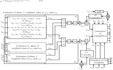
. Schematic diagra
2 shows the bl estimation of ed value of l components. I
b, and vsc), sour
, and iLc) and ion of referen are two prim hm: The first on error or superv gorithm for the
n as follows.
Estimation of W ctive and Reac
P training [32] phase weighte nents (wap, wb
nents (waq, wb
the feedforwa tion, the input sed as
re wo is the sel d ucp are the
in-IJISET - Internatio
am of VSC based D
ock diagram o f reference so load active po In this algorith rce currents (isa
dc bus voltage nce source cu mary modes f ne is a feedforw vised learning
estimation of
Weighted Value ctive Power Co
], [33] algorith ed value of lo
bp, and wcp) an
bq, and wcq ) f
ard and supe layer for thre
lected value of -phase unit tem
onal Journal of Inn
www
DSTATCOM
f the BP trainin ource currents
ower and rea hm, the phase P
a, isb, and isc), l
e (vdc) are requ rrents (i∗sa, i∗
for the operat ward, and the s . The detail ap various contro
e of Average F omponents
hm is used to oad active po nd reactive po from polluted l ervised princip
ee phases (a,
f the initial we mplates.
novative Science, E w.ijiset.com ng algorithm through the active power PCC voltages load currents uired for the
∗sb, and i∗sc).
tion of this second is the pplication of ol parameters Fundamental estimate the ower current ower current load currents ple. In this
b, and c) is
eight and uap,
Engineering & Te
In-ph phase v voltage amplitu The inp estimat The through output express Whe initial w three p the act respect The compon is expre Whe active weighte respect fundam compon section f’(Iap1) compon Simi weighte the load
echnology, Vol. 2 I
hase unit temp voltages (vsa, v
e and the am ude of sensed P
phase unit temp ted as
extracted valu h a sigmoid fu
signals of feed sed as
ere wo1,wap,w weights in the phase weights u
tive power cu tively.
updated weig nents of load c essed as
ere wp(n) and w power compo ed values of tively , and w mental weight
nent of the lo n of the algo
) and µ are nent and the le
ilarly for pha ed values of th d current are ex
Issue 4, April 2015
mplates are esti
vsb, and vsc). It mplitude of th PCC voltages i
mplates of PCC
ues of ILap, I unction as an a dforward sectio
wbp and wcp e hidden layer using the avera urrent compon
ght of phase current “wap”
wap(n) are the onent of load phase “a” at wap1(n) and Z
ted amplitude oad current an rithm at the represented a earning rate.
ase “b” and he active powe xpressed as
5.
ISS
imated using is the relation he PCC voltag
s estimated as
voltages uap,ub
ILbp and ILcp activation func
on (Zap,Zbp a
are the selecte and the updat age weighted v nent as a feed
”a” active po at the nth sam
average weigh currents and t the nth samp Zap(n) are th e of the ac
nd output of nth instant, as the derivat
phase “c”, er current com
SN 2348 – 7968
677 sensed PCC of the phase ge (vt). The
bp and ucp are
p are passed tion, and the and Zcp) are
ed values of ted values of value(wp) of dback signal,
ower current mpling instant
hted value of the updated pling instant, e phase “a” ctive power
feedforward respectively, tive of Iap1
The through estimat three ph
Fig. 2
First frequen extracte which i compon of activ wLpA.
Simi compon fundam
Whe uaq, ub templat
The
extracted valu h a sigmoid fu tion of the fun
hase weights w
. Estimation of ref
order low pa ncy componen ed active powe is shown in fig nents and scali vation function
larly the we nents of the lo mental load curr
ere wo is the bq and ucq are te.
quadrature un
IJISET - Internatio
ues of Iap1, I unction as an ndamental activ wap1, wbp1 and
ference currents us
ass filters are nts. “k” deno er components g. 2. After sep ing to the actua n is between 0
eighted amplit oad currents (w
rent are extract
selected value e the quadratu
nit templates
onal Journal of Inn
www
Ibp1, and Icp1 activation fun ve components
d wcp1 as
sing BP control alg
used to separ otes the scale of current in th parating the lo
al value becaus and 1, it is re
tudes of reac waq,wbq, and ted as
e of the initial ure components
(uaq,ubq and
novative Science, E w.ijiset.com
1 are passed nction to the s in terms of
gorithm
rate the low ed factor of he algorithm w frequency se the output epresented as
ctive power wcq) of the
l weight and s of the unit
ucq) of the
Engineering & Te
The power of three wcp1) feature
phase P
The through estimat
The hidden
layer
echnology, Vol. 2 I
average weigh components (w e phase load ac divided by thre s of DSTATCO
PCC voltage ar
extracted valu h a sigmoid fu tion of Zaq,Zbq
estimated valu layer as input
r (Iaq1,Ibq1, an
Issue 4, April 2015
hted amplitude wp) is estimate ctive power co ee. It is require OM. Mathema
re estimated as
ues of ILaq, I function as an
q and Zcq
ues of Zaq, Zb signals. The th
nd Iq1) before 5.
ISS
e of the fundam ed using the am omponents (wap ed to realize lo atically it is exp
ILbq and ILcq activation fun
bq and Zcq ar hree phase outp
the activation
SN 2348 – 7968
678 mental active mplitude sum p1,wbp1 and oad balancing
pressed as
q are passed nction to the
re fed to the puts of this
IJISET - International Journal of Innovative Science, Engineering & Technology, Vol. 2 Issue 4, April 2015.
www.ijiset.com
ISSN 2348 – 7968
679
be represented as
Where wo1,waq, wbq, and wcq are the selected value of the initial weight in the hidden layer and the updated three weights using the average weighted value of the reactive power components of currents (wq) as a feedback signal, respectively.
The updated weight of the phase “a” reactive power components of load currents “waq” at the nth sampling instant is expressed as
Wq(n) and waq(n) are the average weighted value of the reactive power component of load currents and the updated weight in the nth sampling instant, respectively, and waq1(n) and zaq(n) are the phase “a” weighted amplitude of the reactive power current component of load currents and the output of the feedforward section of the algorithm at the nth instant, respectively. F’(Iaq1) and µ are presented as the derivative of Iaq1 components and the learning rate.
Similarly for phase “b” and “c” the updated weighted values of the reactive power current components of the load current are expressed as
The extracted values of Iaq1, Ibq1 and Icq1 are passé through an activation function to the estimation of the fundamental reactive component in terms of three phase weights waq1, wbq1 and wcq1 as
The average weight of the amplitude of the fundamental reactive power current components(wq) is estimated using the amplitude sum of the three phase load reactive power component of the load current (waq1,wbq1 and wcq1) divided by three. Mathematically it is expressed as
First order low pass filters are used to separate the low frequency component. “r” denotes the scaled factor of the extracted reactive power components in the algorithm which is shown in fig 2. After separating low frequency components
and scaling to the actual value because the output of the activation function is between 0 and 1, it is represented as wLqA.
B. Amplitude Of Active Power Current Components Of Reference Source Currents
An error in the dc bus voltage is obtained after comparing the reference dc bus voltage v*dc and the sensed dc bus voltage vdc of a VSC, anad this error at the nth sampling instant is expressed as
This voltage error is fed to a PI controller whose output is required for maintaining the dc bus voltage of the DSTATCOM. At the nth sampling instant, the output of the PI controller is as follows:
Where kpd and kid are the proportional and integral gain constants of the dc bus PI controller. Vde(n) and vde(n-1) are the dc bus voltage errors in the nth and (n-1)th instant, and wdp(n) and wdp(n-1) are the amplitude of the active power component of the fundamental reference current at the nth and (n-1)th instant, respectively.
The amplitude of the active power current components of the reference source currnet(wspt) is estimated by the addition of output of the dc bus PI controller (wdp) and the average magnitude of the load active currents (wLpA) as
C. Amplitude of Reactive Power Components of Reference Source Currents
An error in the ac bus voltage is achieved after comparing the amplitudes of the reference ac bus voltage vt∗ and the
sensed ac bus voltage vt of a VSC. The extracted ac bus voltage error vte at the nth sampling instant is expressed as
The weighted output of the ac bus PI controller wqq for regulating the ac bus terminal voltage at the nth sampling instant is expressed as
IJISET - International Journal of Innovative Science, Engineering & Technology, Vol. 2 Issue 4, April 2015.
www.ijiset.com
ISSN 2348 – 7968
680
proportional and integral gain constants of the ac bus voltage PI controller.
The amplitude of the reactive power current components of the reference source current (wsqt) is calculated by subtracting the output of the voltage PI controller (wqq ) and the average load reactive currents (wLqA) as
D. Estimation of Reference Source Currents and Generation of IGBT Gating Pulses
Three phase reference source active and reactive current components are estimated using the amplitude of three phase (a, b, and c) load active power current components, PCC voltage in-phase unit templates, reactive power current components, and PCC quadrature voltage unit templates as
The addition of reference active and reactive current components is known as reference source currents, and these are given as
The sensed source currents (isa, isb, isc) and the reference source currents (i∗sa, i∗sb, i∗
sc) are compared, and current error
signals are amplified through PI current regulators; their outputs are fed to a pulse width modulation (PWM) controller to generate the gating signals for insulated-gate bipolar transistors (IGBTs) S1 to S6 of the VSC used as a DSTATCOM.
III. SIMULATION RESULTS AND DISCUSSION
MATLAB with SIMULINK and Sim Power System tool boxes is used for the development of the simulation model of a DSTATCOM and its control algorithm. The performance of the control algorithm is observed under non linear loads.
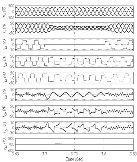
A. Performance of DSTATCOM under non linear load
The dynamic performance of DSTATCOM was studied at PCC. The active current component and reactive current component injection was found successful and power factor correction was studied. The dynamic performance of a VSC-based DSTATCOM is studied for PFC mode at nonlinear loads. The performance indices are the phase voltages at PCC (vs), balanced source currents (is), load currents (iLa, iLb, and
iLc), compensator currents (iCa, iCb, and iCc), and dc bus voltage
(vdc) which are shown in Fig. 3 under varying load (at t = 3.7 to 3.8 s)
conditions. The waveforms of the phase “a” voltage at PCC (vsa), source current (isa), and load current (iLa) are shown in Fig. 4(a)–(c), respectively. The total harmonic distortion (THD) of the phase “a” at PCC voltage, source current, and load cur-rent are found to be 2.86%, 2.94%, and 24.82%, respectively. It is observed that the DSTATCOM is able to perform the functions of load balancing and harmonic elimination with high precision.
B. Performance of DSTATCOM in ZVR mode
The performance of DSTATCOM in ideal zero voltage regulation mode will be done in further studies.
APPENDIX A
AC supply source: three-phase, 415 V (L-L), 50 Hz. Source impedance: Rs =
0.04 Ω and Ls = 2 mH. Nonlinear: three phase full bridge uncontrolled
rectifier with R = 13 Ω and L = 200 mH. Rating of VSC = 10 kVA (approximately 30% higher than the rated value). Ripple filter: Rf = 5 Ω and
Cf = 10 μF. Switching frequency of inverter = 10 kHz. Reference dc bus
voltage: 700 V. Interfacing inductor (Lf ) = 2.75 mH. Gains of PI controller
for dc bus voltage: kpd = 3.1 and kid = 0.9. Gains of voltage PI controller: kpt =
2.95 and kit = 4. Se-lected initial weights: wo = 0.4 and wo1 = 0.2. Learning
IJISET - International Journal of Innovative Science, Engineering & Technology, Vol. 2 Issue 4, April 2015.
www.ijiset.com
ISSN 2348 – 7968
681
IV. REFERENCES
[1] Bhim Singh, Fellow, IEEE, and Sabha Raj Arya “Back-Propagation Control Algorithm for Power Quality Improvement Using DSTATCOM”, VOL. 61, NO. 3, MARCH 2014.
[2]Ortiz, C. Gherasim, M. Manana, C. J. Renedo, L. I. Eguiluz, and R. J. M. Belmans, “Total harmonic distortion decomposition depending on distortion origin,” IEEE Trans. Power Del., vol. 20, no. 4, pp. 2651– 2656, Oct. 2005. [3]T. L. Lee and S. H. Hu, “Discrete frequency-tuning active filter to suppress harmonic resonances of closed-loop distribution power systems,” IEEE Trans. Power Electron., vol. 26, no. 1, pp. 137–148, Jan. 2011.
[4]K. R. Padiyar, FACTS Controllers in Power Transmission and Distribution. New Delhi, India: New Age Int., 2008.
[5] IEEE Recommended Practices and Requirement for Harmonic Control on Electric Power System, IEEE Std.519, 1992.
[6] T.-L. Lee, S.-H. Hu, and Y.-H. Chan, “DSTATCOM with positive-sequence admittance and negative-positive-sequence conductance to mitigate voltage fluctuations in high-level penetration of distributed generation systems,” IEEE Trans. Ind. Electron., vol. 60, no. 4, pp. 1417–1428, Apr. 2013.
[7] Singh, P. Jayaprakash, and D. P. Kothari, “Power factor correction and power quality improvement in the distribution system,” Elect. India Mag., 40– 48, Apr. 2008.
[8] Singh and J. Solanki, “A comparison of control algorithms for DSTATCOM,” IEEE Trans. Ind. Electron., vol. 56, no. 7, pp. 2738–2745, Jul. 2009.
[9] J.C. Wu, H. L. Jou, Y. T. Feng, W. P. Hsu, M. S. Huang, and W. J. Hou, “Novel circuit topology for three-phase active power filter,” IEEE Trans.Power Del., vol. 22, no. 1, pp. 444–449, Jan. 2007.
[10] Vasanthavalli. C, Veliaiswamy. S, “Optimization Technique for Power Quality Improvement Using DSTATCOM”, IJERT, vol 4, issue 4, April 2014.