Transparent Dielectric Resonator Reflectarray
with Bottom-Loading Strip
You-Xuan Tan, Eng-Hock Lim*, and Fook-Loong Lo
Abstract—A transparent dielectric resonator (DR) reflectarray that works in the C-band (6.5 GHz) is proposed in this paper. Here, the reflectarray element has a metallic strip of adjustable length placed underneath to act as a phase shifter. Floquet method is applied for characterizing the reflection properties of the element and a 7×7 full-fledge reflectarray was constructed using glass and the low-cost FR4. By varying the length of the under-loading strip, it is found that the proposed DRA reflectarray element is able to provide a compensating phase of greater than 300◦. Measurements and simulations were conducted to analyze the reflection coefficient, antenna gain, and radiation patterns. The reflectarray has a maximum gain of 14.38 dBi in the broadside direction, and the 1-dB bandwidth of the DRA reflectarray is found to be around 8%. The use of DR has enabled antenna size miniaturization, and it can be useful for the design of small-size reflectarrays.
1. INTRODUCTION
Microstrip patch [1] has become a popular resonator for designing the planar reflectarray because it is planar and simple in structure. A patch resonator with variable size or length is found to be able to introduce phase shift for reflectarray. Nevertheless, conductive and surface wave losses of the patch can be a concern at millimeter wave ranges [2]. It was first shown by Long et al. [3] that the dielectric resonator (DR) can be made an efficient antenna. Since then, the dielectric resonator antenna (DRA) has been extensively explored for various applications because of its advantages such as low loss, wide bandwidth, compact size, and light weight [4, 5]. The use of DR can scale down the antenna size by roughly a factor of 1/√εr, where εr is the dielectric constant of the DR [6].
In 2000, Keller et al. [7] was among the first to propose the use of DRA for reflectarray, where different phase shifts were introduced to the radiating elements by varying the length of the rectangular DRA. It was found that the phase range of the DR reflectarray was comparable with that for the microstrip resonator. However, changing the dimensions of the super-hard DR requires the use of special cutting tools or shaping molds, which may not be convenient in practice. To overcome this problem, slot loading has become one of the popular methods for generating phase shift in the DRA reflectarray elements [8–10]. In [11, 12], the bottom-loading slot is made to have a more complicated shape such as C-slot and I-slot. By varying the arm length of the complex-shaped slot, reasonable reflection phase can be easily achieved. A dual-polarized reflectarray element which is loaded with a windmill-shaped slot is presented in [13] to offer wide bandwidth. Slot is also combined with the notched DRA for designing a dual-band reflectarray, operating in the C and X bands [14].
Another way to introduce phase shift is to combine the DRA with microstrip elements such as patches and strips [2]. A DRA element top-loaded with a rectangular microstrip patch has been proposed in [15], where the patch length is varied to function as a phase shifter. However, the fabrication process can be quite troublesome as the patch has to be manually attached to the top surface of the DRA.
Received 7 May 2015, Accepted 13 June 2015, Scheduled 24 June 2015
* Corresponding author: Eng Hock Lim ([email protected]).
Misalignment of the patch and DRA can reduce the gain. To solve this problem, in this paper, a transparent DRA reflectarray element which has a conductive strip loaded beneath it is proposed to provide a phase range of greater than 300◦. A 7×7 DRA reflectarray was demonstrated to verify the design concept. It is worth to mention that the bottom-loading strip can be easily etched using the standard printed circuit board (PCB) technology, which is able to provide high accuracy for simplifying the tuning process. Although the top-loading case enables easy access to the metallic patch for tuning purpose, the problem is that its manufacturing process can be tedious as it is quite difficult to get the patch stuck to the DR precisely. This problem does not exist in the bottom-loading case. The antenna size of the proposed reflectarray can be reduced by a factor of 1/√εr by increasing the dielectric
constant, and this miniaturization technique can be useful for designing a compact-size reflectarray. For a slot-loaded DRA reflectarray element, electric field can leak through the bottom-loading slot, which may cause the backlobe to increase. On the other hand, the proposed top-patch-loaded DRA reflectarray has a ground plane as shield and therefore very minimum field leakage is possible. The commercial software CST Microwave Studio was used to simulate the unit cell element and the full-fledge DRA reflectarray because its time domain solver has the capability to solve electrically large models. Reasonable agreement was obtained between the simulated and measured results.
2. ANTENNA CONFIGURATION
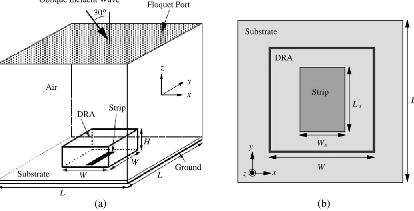
Figure 1(a) shows the Floquet simulation model for the proposed DRA reflectarray element which is loaded with a rectangular strip underneath the DR. The strip is etched on the top surface of a square FR4 (L= 25.38 mm) substrate which has a thickness ofh= 1.58 mm and dielectric constant ofεr = 4.4,
and the reverse surface of the substrate is coated with ground. In this case, the strip lengthLsis varied from 2 mm to 13 mm to function as the phase-shifting element while the strip width (Ws) is made a constant value at 6 mm. A square dielectric resonator (W = 14 mm,H = 6 mm, and dielectric constant of εr = 7) made of Borosilicate Crown Glass, a material which is also known as K9 glass or Pyrex, is then placed right on top of the strip using adhesive. The loss tangent of such material is very low (0.00008) [16] and it is omitted in simulation. A y-polarized wave (6.5 GHz) with an oblique incident angle ofθ= 30◦ (in theφ= 180◦ direction) is generated from the port and it is guided to propagate in the direction of the DRA element. This is to imitate the full-fledge reflectarray that is designed to have a side-fed horn suspended at the same angle. The simulated reflection phase (S-curve) and reflection magnitude (reflection loss) as a function of strip length were plotted in Figure 2 at 6.5 GHz. It can be
Floquet Port Oblique Incident Wave
DRA
Ground H
L W
Strip
Substrate
W Air
L
z
y
x 30o
L
W Ws
Ls
z y
x Substrate
DRA
Strip
(a) (b)
-400 -300 -200 -100
Refflection Phasee ( )
2 0
6
Strip LLength, L (mm)
8 10
Reflectionn Loss (dB)
12
o
4
s
-3 -2 -1 0
Figure 2. Simulated reflection phase (S-curve) and reflection magnitude at 6.5 GHz as a function of strip length. (Resolution = 0.1 mm).
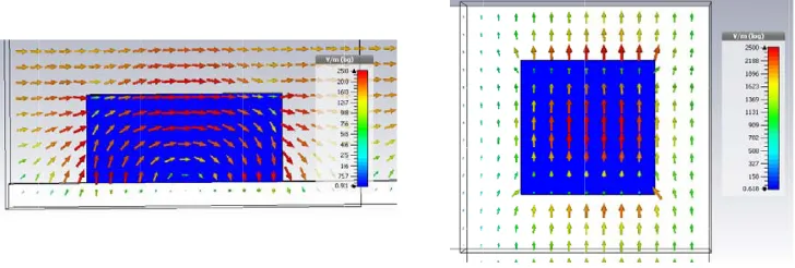
Figure 3. Electric field distribution of the DRA for the case of Ls = 13 mm, working at the T E111 mode.
seen from the magnitude response that reflection loss at the Floquet port maximizes when the length of the conductive strip is around 8 mm. AsLsgets from 2 mm up to 13 mm (resolution of 0.1 mm), the
reflection phase shifts down from−38.6◦ to −354.6◦, giving a phase range of 316◦. This phase range is sufficient for designing a small-size reflectarray. The electric field distribution of the DRA for the case of Ls = 13 mm is shown in Figure 3 and it is found that the DRA is working at its TE111 mode. For the slot-loaded DRA reflectarray element, electric field can leak through the bottom-loading slot, which may cause the backlobe to increase. On the other hand, the proposed strip-loaded DRA reflectarray has a ground plane as shield and therefore very minimum field leakage is possible.
3. RESULTS AND DISCUSSION
by the receiving horn is read (|S21born|) and the antenna gain of the reflectarray can therefore be calculated as Gain (dBi) = |S21refl| − |S21born| −20 log10(λ/4πR), where λ is the operating frequency and the final term is taking account of the free space loss.
Figure 4(a) illustrates the configuration of the proposed DRA reflectarray. As can be seen from the figure, the DRA radiating element that was described in Figure 1 is now arranged in an array of 7×7, summing up with a total of 49 radiating elements. The optimum spacing between any two of the reflectarray elements is usually in the range of 0.5−0.6λ [17]. In this paper, the element spacing
d1 =L is set to be 25.38 mm, which is 0.55λat 6.5 GHz, and the distance d2 between the element and the edge of the board is selected to be L/2 (or 12.69 mm) to make the edge element a complete cell. The board size D of the reflectarray is 177.69 mm. The feeding horn antenna is placed at f from the center of the grounded substrate with an inclination angle of 30◦ with respect to the center (X4, Y4). The use of side-feed scheme can minimize the blockage of signal at the broadside direction. For this design, anf /D ratio of 1.15 is used. Figure 5 shows the prototype of the 7×7 DRA reflectarray.
The simulated and measured radiation patterns of the proposed 7×7 DRA reflectarray are shown in Figure 6 in thexz plane (H plane) andyz plane (E plane). As can be observed from Figure 6(a), it has a maximum measured gain of 14.24 dBi (simulation 15.58 dBi) in the broadside direction (θ = 0◦) at 6.5 GHz. The co-polarized field is larger than its cross-polarized counterpart by ∼25 dB in this direction. In Figure 6(b), the maximum measured gain in the broadside direction is 14.38 dBi (simulation 15.58 dBi), with the co-polarized field larger than its cross-polarized field by ∼39 dB in the broadside.
FR4 d 1
f Feed Horn
D 30o
Unit Element z
y x
Ground
d 2
X1
Y1
Y2
Y3
Y4
Y5
Y6
Y7
X2 X3 X4 X5 X6 X7
z y
x
(a) (b)
Figure 4. Configuration of the proposed 7×7 DRA reflectarray. (a) Front view. (b) Top view.
Gain (dBi)
θ (degree)
Co-pol (Simulated) Co-pol (Measured) Cross-pol (Measured)
Gain (dBi)
-80 -60 -40 -20 0 20 40 60 80
θ (degree)
Co-pol (Simulated) Co-pol (Measured) Cross-pol (Measured)
-80 -60 -40 -20 0 20 40 60 80
(a) (b)
-30 -20 -10 0 10 20
-30 -20 -10 0 10 20
Figure 6. Simulated and measured radiation patterns of the DRA reflectarray. (a)xz-plane (φ= 0◦).
yz-plane (φ= 90◦).
Frequency (GHz)
6 6.2 6.4 6.6 6.8
0 5 10 15 20 Gain (dBi)
Simulated Measured
7
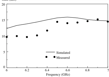
Figure 7. Simulated and measured maximum gains across frequency.
For the ease of demonstrating the design idea, the array size is selected to be 7×7. The reflectarray can be designed to have higher gain if more elements are deployed. Figure 7 shows the simulated and measured maximum gains across frequency. The measured 1-dB gain bandwidth of the DRA reflectarray is 8% (simulation 9%).
Reflection Loss (dB)
-3 -2 -1 0
d = 0.501 λ
d = 0.601 λ d = 0.551 λ
Reflection Phase ( )
-400 -300 -200 -100 0
d = 0.501 λ
d = 0.601 λ d = 0.551 λ
Strip Length, L (mm)s
Strip Length, L (mm)s
2 4 6 8 10 12 2 4 6 8 10 12
o
(a) (b)
Figure 8. The effect ofd1 (orL) on (a) reflection loss and (b) reflection phase.
]
Reflection Loss (dB)
-5 -4 -3 -2 -1 0 6.0 GHz 7.0 GHz 6.5 GHz
Reflection Phase ( )
-600 -400 -200 0 200 6.0 GHz 7.0 GHz 6.5 GHz
Strip Length, L (mm)s
2 4 6 8 10 12
Strip Length, L (mm)s
2 4 6 8 10 12
o
(a) (b)
Figure 9. Reflection characteristics of the unit element at different frequencies.
Reflection Loss (dB)
-4 -3 -2 -1 0
W = 4 mms
W = 6 mms
W = 8 mms
Reflection Phase ( )
-400 -300 -200 -100 0
W = 4 mms
W = 6 mms
W = 8 mms
Strip Length, L (mm)s
2 4 6 8 10 12
Strip Length, L (mm)s
2 4 6 8 10 12
o
(a) (b)
Gain (dBi)
-30 -20 -10 0 10 20
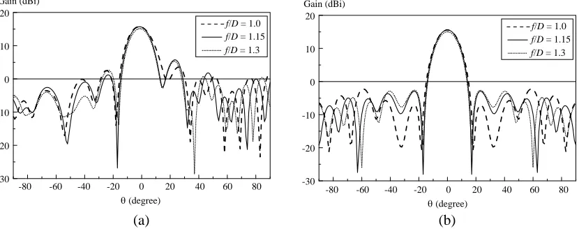
f/D = 1.15 f/D = 1.3 f/D = 1.0
Gain (dBi)
-30 -20 -10 0 10 20
f/D = 1.15 f/D = 1.3 f/D = 1.0
θ (degree)
-80 -60 -40 -20 0 20 40 60 80
θ (degree)
-80 -60 -40 -20 0 20 40 60 80
(a) (b)
Figure 11. The co-polarized radiation patterns for differentf /Dratios. (a) xz-plane (φ= 0◦). (b)yz -plane (φ= 90◦).
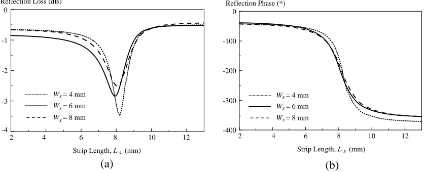
range. Figure 10 illustrates the reflection characteristics of a single DRA element as a function of the strip width (Ws), which is varied from 4 mm, 6 mm, to 8 mm, where its reflection loss maximizes at the
strip length (Ls) of 8 mm. Figure 10(b) shows that an additional phase range of 10◦ is possible for the
case of 4 mm, but it has a steeper gradient. Change of reflection loss implies that the under-loading metallic strip can dissipate part of the energy of the incident wave.
By keeping all the design parameters unchanged, thef /Dratio of the full-fledge DRA reflectarray is now varied from 1.0 to 1.3. Radiation patterns are generated as a function of the elevation angle (θ) and the results are shown in Figure 11. Among all, the antenna gain is the lowest in the broadside direction for the case of f /D = 1.3. The other two cases have almost the same antenna gain. The ratiof /D= 1.15 is selected because the sidelobe level of the reflectarray is slightly better than that at
f /D= 1.
4. CONCLUSION
A DRA reflectarray element loaded with a variable strip beneath the DR has been proposed, and its design procedure has been discussed. Simulation and experiment for an array of 7×7 elements have been carried out, and reasonable agreement is found between the simulated and measured results. It has been proven that a DRA loaded with an underlaid strip can be deployed for reflectarray design. The strip beneath the DRA is able to function as a phase shifter for compensating the phase of the incoming wave beam. The main advantage of the proposed reflectarray structure is that the phase-shifting element can be completely integrated into the DRA, and it does not require extra footprint.
ACKNOWLEDGMENT
The work described in this paper was supported by a UTAR Research Fund (Project No. 6200/LA9).
REFERENCES
1. Pozar, D. M., S. D. Targonski, and H. D. Syrigos, “Design of millimeter wave microstrip reflectarrays,” IEEE Trans. Antennas Propag., Vol. 45, No. 2, 287–296, Feb. 1997.
2. Jamaluddin, M. H., R. Gillard, R. Sauleau, P. Dumon, and L. Le Coq, “Reflectarray element based on strip-loaded dielectric resonator antenna,” Electron. Lett., Vol. 44, No. 11, 664–665, May 2008. 3. Long, S. A., M. W. McAllister, and L. C. Shen, “The resonant cylindrical dielectric cavity antenna,”
4. Luk, K. M. and K. W. Leung, Eds., Dielectric Resonator Antennas, Research Studies Press, UK, 2003.
5. Petosa, A., Dielectric Resonator Antenna Handbook, Artech House Inc., Norwood, 2007.
6. Lim, E. H. and K. W. Leung, “Transparent dielectric resonator antennas for optical applications,”
IEEE Trans. Antennas Propag., Vol. 58, No. 4, 1054–1059, Apr. 2010.
7. Keller, M. G., J. Shaker, A. Petosa, A. Ittipiboon, M. Cuhaci, and A. Antar, “A Ka-band dielectric resonator antenna reflectarrays,” 30th European Microwave Conference, 272–275, Paris, France, Oct. 2000.
8. Zainud-Deen, S. H., A. M. Abd-Elhady, A. A. Mitkees, and A. A. Kishk, “Dielectric resonator reflectarray with two DRA sizes and varying slot loading,”IEEE APSURSI, 1–4, Jul. 2010. 9. Abd-Elhady, A. M., S. H. Zainud-Deen, A. A. Mitkees, and A. A. Kishk, “X-band linear polarized
aperture-coupled DRA reflectarray,” ICMMT, 1042–1044, May 2010.
10. Abd-Elhady, A. M., S. H. Zainud-Deen, A. A. Mitkees, and A. A. Kishk, “Slot-loading rectangular dielectric resonator elements reflectarray,” IEEE MECAP, 1–3, Oct. 2010.
11. Dzulkipli, N. I., M. H. Jamaluddin, and M. F. M. Yusof, “Design of alphabet shaped slot-loaded dielectric resonator reflectarray antenna at 12 GHz,”IEEE APACE, 334–337, Dec. 2012.
12. Dzulkipli, N. I., M. H. Jamaluddin, and M. F. M. Yusof, “Design of dielectric resonator reflectarray antenna loaded with C-slot,”IEEE RFM, 189–192, Dec. 2013.
13. Ahmadi, F., K. Forooraghi, Z. Atlasbaf, and B. Virdee, “Dual linear-polarized dielectric resonator reflectarray antenna,”IEEE Antennas Wireless Propagat. Lett., Vol. 12, 635–638, 2013.
14. Alsath, M. G. N., M. Kanagasabai, and S. Arunkumar, “Dual-band dielectric resonator reflectarray for C/X-bands,” IEEE Antennas Wireless Propagat. Lett., Vol. 11, 1253–1256, 2012.
15. Jamaluddin, M. H., R. Gillard, R. Sauleau, L. Le Coq, X. Castel, R. Benzerga, and T. Koleck, “A dielectric resonator antenna (DRA) reflectarray,” EuMC, 25–28, Sep. 2009.
16. Lim, E. H., K. W. Leung, X. S. Fang, and Y. M. Pan, Encyclopedia of Electrical and Electronics Engineering: Transparent Antennas, John Wiley and Sons, 2015.