18th International Conference on Structural Mechanics in Reactor Technology (SMiRT 18) Beijing, China, August 7-12, 2005 SMiRT18-W101-7
STRESS ANALYSIS ON MULTIPLE OPENING EXTRUDED OUTLETS
OF HEADERS
Weiya Jin
Zhejiang University of Technology
Phone: 0571-88320201
Fax: 0571-88320763
E-mail: [email protected]
Zengliang Gao
Zhejiang University of Technology
Phone: 0571-88320201
Fax: 0571-88320763
E-mail:[email protected]
Weiming Sun
Zhejiang University of Technology
Phone: 0571-88320201
Fax: 0571-88320763
E-mail: [email protected]
Kangda Zhang
Zhejiang University of Technology
Phone:0571-88320482
Fax: 0571-88320763
E-mail: [email protected]
ABSTRACT
Many kinds of multiple opening extruded outlets are widely used in shells, drums and headers of power boilers, petrochemical and nuclear power equipments. To improve the stress distribution of headers and be manufactured easily, drawing forming is applied for extruded outlets replacing welded structure. Finite element analysis is used to check the stress distribution of extruded outlets of headers.
The ANSYS software is used for FEA. According to the shape and location of the extruded outlets of headers, several FE models are established for longitudinal single row, transverse 90 degree double rows, non-radial double rows, staggered pattern rows. Considering the inside and outside corner radius of the extruded outlets and the pitch between the extruded outlets, Solid95 element is used to mesh the models. According to comparison of FEA results and the actual headers stress measurement with reinforcement rules in ASME Code and Chinese Boiler Design Standard (GB/T9222), several propositions are put forward.
Keywords: Extruded Outlets, Stress Analysis, FEA
1. INTRODUCTION
Many kinds of multiple opening extruded outlets are widely used in shells, drums and headers of power boilers, petrochemical and nuclear power equipments. The corner welded lines are used to connect heating pipes with the extruded outlet. This welded structure not only produces high regional stress in discontinuous region of structure, but also is difficult to verify reliably. Therefore, the defects of welding line will cause crack and further lead to fracture and leak of the extruded outlet. To improve the stress distribution of headers and be manufactured easily, drawing forming is applied for extruded outlets replacing welded structure. The drawing forming extruded outlet can be forged in whole to improve dimension precision, surface quality and material stability.
The ANSYS finite element analysis software is applied to calculate stress distribution of a typical extruded outlet. Two calculating cases, including stable case and cold startup case, are taken into account. The results, including the thermal loads result from pressure and temperature at the joint between the drawing tube and the extruded outlet, and from discontinuous region of the internal or external wall of the extruded outlet, can be referenced by engineering applications.
Copyright © 2005 by SMiRT18
2. DRAWING FORMING EXTRUDED OUTLET
The structure of the calculated drawing forming extruded outlet is shown in Fig.1. The material of the structure is SA335-P91, whose major properties and allowable stress is shown in Table 1, or can be refer to ASME Boiler and Pressure Vessel Code, Section. II, “Material” Part. D-properties.
In cool startup case, the change curve of temperature and pressure is shown in Fig.2.
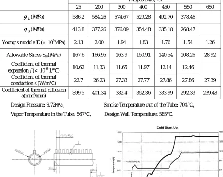
Table 1 The material properties of SA335-P91
The parameters of the stable case of the drawing forming extruded outlet are listed as follows:
Temperature( )
25 200 300 400 450 550 650
b
σ
(MPa) 586.2 584.26 574.67 529.28 492.70 378.46s
σ
(MPa) 413.8 377.26 376.09 354.48 335.18 268.47Young’s module E (10 5MPa) 2.13 2.00 1.94 1.83 1.76 1.54 1.26
Allowable Stress Sm(MPa) 167.6 166.95 163.9 150.91 140.54 108.26 28.92 Coefficient of thermal
expansion α(10 -6 1/ ) 10.62 11.33 11.65 11.97 12.14 12.46 Coefficient of thermal
conduction λ(W/m) 22.7 26.23 27.33 27.77 27.86 27.86 27.39
Coefficient of thermal diffusion
a(mm2/min) 399.5 401.34 382.4 352.36 333.99 292.33 239.48 Design Pressure: 9.72MPa, Smoke Temperature out of the Tube: 704,
Vapor Temperature in the Tube: 567, Design Wall Temperature: 585 .
Fig.1 The Structure of the Calculated Fig.2 The Change Curve of Temperature and
Drawing Forming Extruded Outlet Pressure in Cool Startup Case
According to the Fig.2, there are total 150 minutes from normal temperature to work temperature. The most restricted period is the 5 minutes from 20 to 25 minutes in which temperature is increased from (151 ) to ( ). During this period, the temperature difference between the inside wall and outside wall temperature is maximum. The increasing rate of the temperature reaches .
F
ο
322
min / C ο
C
ο
F ο
700 371οC
42 5 / ) 161 371 (
v= − =
According to the simplified calculation of stable temperature field, the temperature difference between the inside wall and outside wall of the extruded outlet can be approximately obtained as follows:
Copyright © 2005 by SMiRT18 C R R R R R a T i o o i o ο 83 8 . 123 9 . 161 ln 9 . 161 2 8 . 123 9 . 161 400 4 42 ln 2 4 2 2 2 2 2
2 =
− − × × × = − − = ν δ
By the same means, the temperature difference between the inside wall and outside wall of the tubes are .
C T =2ο
δ
3. FINITE ELEMENT ANALYSIS OF DRAWING FORMING EXTRUDED OUTLET
For fonts, we have no limitation against the final paper for review and comments because your final paper will be supplied to us in the printed form. However, we have strong restrictions for your final paper supplied us in the electrical form, as described in section 1.3.2 of Format of Final Paper. Acceptable fonts are limited in the digital version of you final paper to “Arial”, “New Times Roman”, “Courier”, or “Symbol.”.
3.1 FF MODELING IN STABLE CASE
In stable case, in order to analyze the interaction of nozzle of each tube, and the interaction between the nozzle of first tube and ending cover of extruded outlet, five heating tubes near ending cover of extruded outlet are modeled. The most complex structure of the models is the corner region that joint tubes and extruded outlet, whose corner radius is required according the design. A cylinder whose length is 500mm is added to simulate actual extruded outlet, and to avoid the constraints of the end surface affecting on the drawing forming tube.
Element solid 45 is used to mesh the structure. Total 33072 nodes and 137417 elements are produced. At the joint region concerning drawing forming tube connected with extruded outlet, end cover connected with extruded outlet, and at several regional discontinuous region, refined elements are used to calculate more accurately. In order to be easy to analyze the results’ figure, the FE model is divided through axial and radial directions. The mesh figure is shown in Fig.3.
In stable case, the temperature difference between the inside wall and outside wall is little, so affection of the temperature stress is not necessarily considered. Only the internal pressure acting on the inside surface of extruded outlet, end cover and all drawing forming tubes is applied. The symmetric constraints are applied on the end surface of the cylinder.
3.2 FF MODELING IN COLD STARTUP CASE
In cold startup case, the modeling and mesh of the structure is similar to those in stable case, except that thermal element solid 70 is used to mesh instead of element solid 45. According the requires in the cold startup case, the inside and outside surface temperature of extruded outlet are respectively 180 and263 , and the
inside and outside surface temperature of drawing forming tubes are respectively and182 . No pressure is
considered. The parameters of material properties are shown in Table 1, referring to the ASME standard and varying along with the temperature change.
C ο C ο C ο
180 οC
3.3 FE RESULTS IN STABLE CASE
The stress intensity distribution of the structure is shown in Fig. 4. The general maximum deformation is 0.079mm, and the radial maximum deformation is 0.034mm. The high stress regions appear at the inside corner in the joint region connected the drawing forming tube with the extruded outlet, and the joint region connected end cover with extruded outlet. The stress results and maximum stress locations of several important regions are listed in Table.2.
Table 2 Stress Results and Maximum Stress Locations in Stable Case
Maximum Stress Locations
Stress Intensity
Principle Stress
Locations S1 S2 S3 SINT
Inside corner of the
drawing forming tubes 123.91 Inside corner of the end
plate 80.005
Inside surfaces of the extruded
outlet
3540 2530 -9-10 4548
outside corner of the
drawing forming tubes 37.153 outside corner of the
drawing forming tubes 69.02
Outside surfaces of the extruded outlet
2530 1214 -30 2530
Copyright © 2005 by SMiRT18
Fig. 3 the mesh of the structure Fig.4 Stress Intensity Distribution in Stable Case
3.4 FE RESULTS IN COLD STARTUP CASE
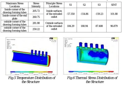
In cold startup case, temperatures are first applied on the structure to obtain the temperature distribution of the structure. Then element 77 is switched to element 45, the temperature distribution is applied as thermal loads acting on the structure to calculate the thermal stress of the structure. The temperature distribution of the structure is shown in Fig.5, and the thermal stress distribution of the structure is shown in Fig.6. The stress results and maximum stress locations of several important regions are listed in Table.3.
Table 3 Stress Results and Maximum Stress Locations in Cold Startup Case
Fig.5 Temperature Distribution of Fig.6 Thermal Stress Distribution of
Maximum Stress Locations
Stress Intensity
Principle Stress
Locations S1 S2 S3 SINT
Inside corner of the
drawing forming tubes 205.72 Inside corner of the end
plate 260.75
Inside surfaces of the extruded
outlet
-57.350 -154.86 -159.23 101.88
outside corner of the
drawing forming tubes 281.88 outside corner of the
drawing forming tubes 250.22
Outside surfaces of the extruded
outlet
184.29 180.94 87.408 96.879
the Structure the Structure
4. CALCULATION RESULTS AND ANALYSIS 4.1 Calculation results and analysis in stable case
The principle stress of the structure, resulting from the design internal pressure 9.72MPa is the primary membrane stress acting on the major region of the drawing forming extruded outlet. According to standard GB/T9222-88, is the stress in low compressive stress region. The principle stress of the inside wall and outside wall are both less than 77MPa, which is the allowable stress intensity of SA335-P91 at 585
temperature, and meet the requirement of standard of GB/T9222-88. Therefore, the low stress region is safe.
m P
m P
C ο
The finite element analysis reveals that higher stress regions appear at the inside corner in joint region connected drawing tubes with extruded outlet, or connected end plate with extruded outlet. According to the relevant standards, the higher stresses belong to secondary stress and primary bending stress. The allowable stress
Copyright © 2005 by SMiRT18 of these higher stresses is and 1 , while is the allowable stress at design temperature of the structure.
The calculation results reveal that the maximum stress of the inside corner in the joint region connected the drawing forming tubes with extruded outlet is 123.91MPa, and the maximum stress of the inside corner in the joint region connected the end plate with extruded outlet is 123.91MPa. These two maximum stresses are both less than the allowable stress of SA335-P91 at temperature. Therefore, the higher stress region is safe.
m
S
3 .5Sm
585
m
S
C ο
4.2 Stress Analysis of Higher Stress Region in Cold Startup Case
During the sharply increasing temperature period in cold startup case, the temperature difference results from the radial different temperature along with the wall is the secondary stress, , in higher stress region. The allowable stress of is3 , while is the allowable stress at the highest temperature during the increasing
temperature period. According to the calculated results, the maximum stress occurs at the outside corner in the joint region connected the drawing forming tubes with extruded outlet is 281.88MPa, and the maximum stress occurs at the inside corner in the joint region connected the end plate with extruded outlet is 260.75MPa. These two maximum stresses are both less than the allowable stress of SA335-P91 at temperature. Therefore, during the process of cold startup the structure is safe.
Q
Q Sm Sm
C ο
371
4.3 The Circulate Times Analysis in Cold Startup Case
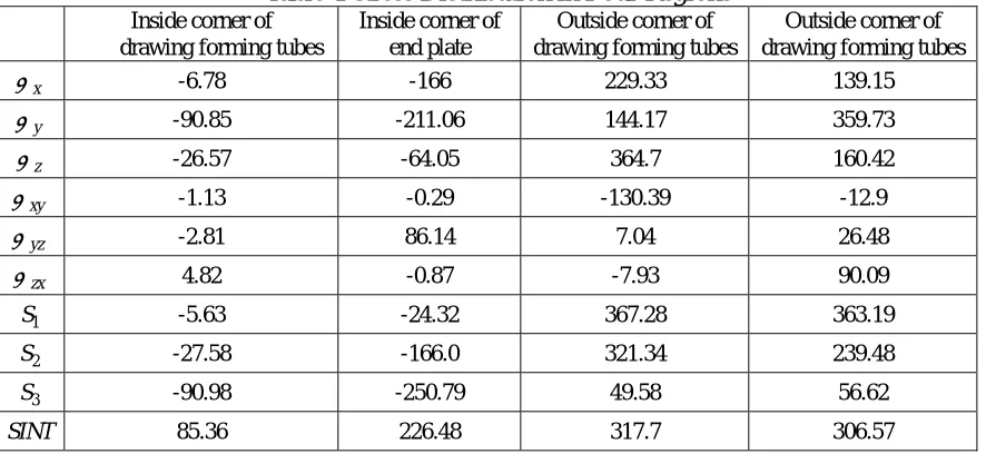
The maximum stress scopes in which stress change from the lowest to the highest exist respectively in stable case and cold startup case. Because the causing loads in these two cases are differently by thermal load or pressure, the direction of the primary stress is different. According to the regulation of standard of ASME and JB4732, when the direction of the principle stress is changing in a cycle the maximum cyclic stress intensity must be calculated. The finite element analysis reveals that the maximum cyclic stress intensities most possibly occur at inside or outside corner in the joint region connected drawing forming tubes with extruded outlet, and the inside corner in the joint region connected end plate with extruded outlet. So σx σy σz σxy σyz and σzx these six stresses
are needed to calculate each stress difference in a cycle. The principle stress and can be obtained through these six stresses. Then the maximum principle stress is adopted as the maximum stress change range, as shown in table 4.
1 S
S 2 S3
The stress scope used to fatigue analysis equals to( . In absence of fatigue design curve above
375 temperature in standard of GB/T9222-88 and JB4732-95, only data and curve (Fig T-1420-1D) of
a
S SINT)max/2
Mo
Cr 1
4 1
2 −
t a a =S /E ε
(SA335-P22) in standard of ASME III, which are similar to those of SA335-P91, are used to
analyze. To meet the requirement of this fatigue design curve, stress scope can be converted to strain scope , then choose the corresponding curve is chosen to obtain allowable cycles, as shown in table 5.
a
S
Table 4 Stress Distribution in Four Regions
Inside corner of drawing forming tubes
Inside corner of end plate
Outside corner of drawing forming tubes
Outside corner of drawing forming tubes
x
σ -6.78 -166 229.33 139.15
y
σ -90.85 -211.06 144.17 359.73
z
σ -26.57 -64.05 364.7 160.42
xy
σ -1.13 -0.29 -130.39 -12.9
yz
σ -2.81 86.14 7.04 26.48
zx
σ 4.82 -0.87 -7.93 90.09
1
S -5.63 -24.32 367.28 363.19
2
S -27.58 -166.0 321.34 239.48
3
S -90.98 -250.79 49.58 56.62
SINT 85.36 226.48 317.7 306.57
Table 5 Fatigue Life of Extruded Outlet
Copyright © 2005 by SMiRT18 Maximum Stress Intensity
SINT MPa
Stress Scope
a
S MPa
Straing Scope
a
ε Cycle N
317.7 158.9 -3
1.1 10× 2 10× 5
5. CONCLUSIONS
5.1 The finite element analysis of the drawing forming extruded outlet indicates that in stable case, the major stress of the structure is less than the allowable stress. Although the maximum regional stresses occur at the inside corner in the joint region connected the drawing forming tubes with extruded outlet, or in the joint region connected the end plate with extruded outlet, the maximum stresses both meet the requirement of the standard. So the structure is safe in stable case. In cold startup case, the maximum regional stress occurs at the outside corner in the joint region connected drawing forming tubes with extruded outlet and meet the requirement of standard. So the structure is safe in cold startup case.
5.2 Considering the circulation of the cold startup case, the maximum stress intensity change scope, which is the main factor affecting the circulation life of the structure, is and occurs at the outside corner of the joint region connected the drawing forming tubes with extruded outlet. According the standard of ASME,
cycles is allowable for circulation of cold startup.
MPa 7 . 371
5
10 2×
5.3 The inside and outside corner of the drawing forming tubes are both formed by punch. This drawing forming tubes are obviously superior than welded structure, especially in the structure whose cold startup is frequent.
5.4 By finite element analysis, stress distributions and maximum stress location can be easily obtained. Finite element analysis make it possible to optimize the weak parts of the structure, to apply fatigue design in the structure whose primary stress directions change. So the design of the extruded outlet by standard, aiding finite element analysis, can make whole structure perfectly.
REFERENCES [1]
[2]
[3] [4] [5] [6]
[7]
Donald PittsLeighton Sissom Schaums outline of Theory 4 Problems of Heat Transfer,2nd Edition 1998 McGraw-Hill Companies. Inc.
Wang Honggang, The conspectus of thermal elastic mechanics, Tsinghua University publishing company, 1989.
Warren C Young, Roarks Formulas for stress and strain(7 Edition), McGraw-Hill Companies. Inc., 2002 ASME Boiler and Pressure Vessel Code, Sec.II Material, Part.D-properties2001
ASME VIII, Division 2, Pressure Vessel2001
Chinese Standard, JB 47321995Steel Pressure Vessel-standard of analysis design. Chinese Standard, GB9222-1988, Standard of Strength Calculation for water pipe boiler