Composite Section Design for Minimum
Weight in Structural Application
Devendra B. Sonawane
1, Prof. R. N. Garad
2, Pratik Satav
3P.G. Student, Department of Mechanical Engineering, Siddhant College of Engineering, Pune, Maharashtra, India1 Assistant Professor, Department of Mechanical Engineering, Siddhant College of Engineering, Pune, Maharashtra,
India2
Pratik Satav, Industrial Expert, Pune, Maharashtra, India3
ABSTRACT: A composite structure consist of two face sheets made from material such as metal or fibre composite bonded to light weight material called as core. This light weight composite structure used in application of aircrafts, wind turbine blades, marine and also in other industrial sectors. In this composite structure have top and bottom side mild steel face sheets are used and for core material selected glass fiber reinforced polymer (E-glass/epoxy). In this way minimum weight and increasing of strength can be obtained. In this paper analysis of composite structure is done in Ansys work bench and Total deformation and equivalent stress is analyzed. The model of composite structure is generated in CATIA. The rectangular core composite structure results are compared with circular core composite structure and V core composite structure of with same weight and same boundary conditions and loading.
KEYWORDS: E-Glass/Epoxy, CATIA V5R20, Composite structure, Ansys 14.5, Mild steel
I. INTRODUCTION
A composite structure consists of two face sheets made from mild steel material and bonded by thick light weight material called core. During loading condition of composite structure the top and bottom side of the face sheets which is made from mild steel which support bending loads and core material which is E-glass/epoxy transfer the shear force between the faces in composite structure at loading condition. The top side plate and bottom side of sheets of composite structure which provide structural stiffness and protect the core of composite structure from damages and from environmental effects. During loading condition of composite structure the face sheets which take tensile as well as compressive stress and core which transfer shear loads between faces and provide high bending stiffness. In this paper a composite structure with core made of E-glass/epoxy and mild steel face sheets are considered.
II. LITERATUREREVIEW
III.ANSYSWORKBENCH
ANSYS Workbench is generally used to perform your analysis (Finite Element Analysis) activities. ANSYS Workbench has the following modules.
Simulation
It is for performing structural and thermal analyses using the ANSYS solver.
Meshing
It is for generating a mesh for Mechanical, Electromagnetic or CFD application.
Design Modeler
Design modeler creates and modifies geometry in preparation for analysis. It generates 2-D sketches and converts them into 2-D or 3-D models. Generate 2-D sketches and convert them into 2-D or 3-D models. Modify 2-D and 3-D geometry. To import existing CAD geometry. Create surface bodies in preparation for FE shell analysis.
Design Xplorer and Design Xplorer VT
It is for investigating the effect of variations input to the response of the system.
FE Modeler
It is for translating a Nastran mesh for use in ANSYS.
Advanced CFD
It is for performing CFD analyses using the CFX Solver.
Advanced Meshing
It is for generating complex CFD grids and sophisticated structural FEA meshes using full ICEM CFD version.
IV.DESIGNANDANALYSISOFCOMPOSITESTRUCTURES
Composite structures are modeled in CATIA. The top and bottom plates are modeled by using pad command and also the core part is modeled in CATIA. The three parts are assembled by using assembling command. Then geometry of composite structures are saved in STP format and imported to ANSYS workbench. In ANSYS Workbench the geometry of composite structures show three contact pairs. Materials properties are given to the individual part of composite structures i.e. top and bottom plates are selected and mild steel properties are given to them. Now core is selected and E-glass/epoxy properties are given to them. Now mesh the geometry of composite structure as optimum meshing size and select optimum mesh size 3mm. The structural analyses of composite structures are done by fixing the bottom plate at bottom side and force is applied at top face of the plate. Now by solving the structure the total deformation and equivalent stress are noted. 3D models of composite structures are model in CATIA.
Top and bottom plate Material of all composite structures – Mild steel.
Core material of all composite structures – Glass fiber reinforced polymer (E-Glass/Epoxy).
TABLE I: Material properties of E-Glass/epoxy
Properties Value Tensile modulus along X-direction (Ex) 34000 MPa Tensile modulus along Y-direction (Ey) 6530 MPa Tensile modulus along Z-direction (Ez) 6530 MPa Tensile strength of the material 900 MPa Compressive strength of the material 450 MPa Shear modulus (Gxy) 2433 MPa Shear modulus (Gyz) 1698 MPa Shear modulus (Gzx) 2433 MPa Poisson ratio along XY-dirction(μxy) 0.217
Poisson ratio along YZ-direction (μyz) 0.366
Poisson ratio along ZX-direction (μzx) 0.217
A. CIRCULAR CORE COMPOSITE STRUCTURE
Top and bottom side plate of all composite structures – 100mmx100mmx5mm. Inner diameter of circular core - 3mm
Outer diameter of circular core - 20.5mm Length of circular core - 100mm
Core Height- 20.5mm
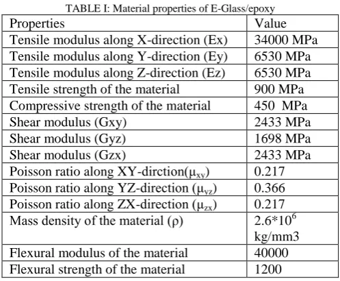
(c)
Fig. 1 Total Deformation and equivalent stress and position of applying force in Circular core composite structure (a) Position of applying load of 10000N on circular core composite structure (b) Total deformation in circular core composite structure by applying load of 10000N (c) Total
deformation in circular core composite structure by applying load of 10000N.
Fig. 1 shows that total deformation and equivalent stress of circular core composite structure by applying load 10000N. When 10000N load apply on circular core composite structure then total deformation is 0.054843mm and equivalent stress 10.389Mpa noted.
B. V CORE COMPOSITE STRUCTURE
Top and bottom side plate of all composite structures – 100mmx100mmx5mm. V core = 25mmx25mmx9mm
Length of V core- 100mm Core Height- 20.5mm
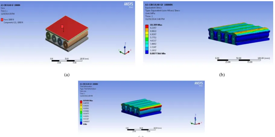
(a) (b)
(c)
Fig. 2 Total Deformation and equivalent stress and position of applying force in V core composite structure (a) Position of applying load of 10000N on V core composite structure (b) Total deformation in V core composite structure by applying load of 10000N (c) Total deformation in V core
composite structure by applying load of 10000N.
Fig. 2 shows that total deformation and equivalent stress of V core composite structure by applying load 10000N. When 10000N load apply on V core composite structure then total deformation is 0.074499mm and equivalent stress 15.264Mpa noted.
C. RECTANGULAR CORE COMPOSITE STRUCTURE DIMENSIONS
Top and bottom side plate of all composite structures – 100mmx100mmx5mm. Rectangular core = 100mmx20.5mmx9mm
Core Height- 20.5mm
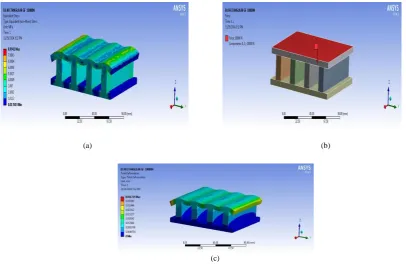
(c)
Fig. 3 Total Deformation and equivalent stress and position of applying force in rectangular core composite structure (a) Position of applying load of 10000N on rectangular core composite structure (b) Total deformation in rectangular core composite structure by applying load of 10000N (c) Total
Fig. 3 shows that total deformation and equivalent stress of rectangular core composite structure by applying load 10000N. When 10000N load apply on rectangular core composite structure then total deformation is 0.041719mm and equivalent stress 8.9941Mpa noted.
V. RESULTANDDISCUSSION
The table 2 shows the obtained value of total deformation of the various composite structures for an applied force of 1000N, 5000N, 10000N. The table 3 shows the obtained value of equivalent stress of the various composite structures for an applied force of 1000N, 5000N, 10000N. The total deformation and equivalent stress results are noted in same weight of all composite structures.
TABLE II: Total deformation comparison of all composite structure.
Force (N)
Circular core composite Structure Deformation
(mm)
V core composite Structure Deformation
(mm)
Rectangular core composite Structure
Deformation (mm) 1000 0.0054843 0.0074499 0.0041719 5000 0.027421 0.03725 0.020859 10000 0.054843 0.074499 0.041719
Table II shows that total deformation of all composite structure. By applying 10000N force on circular composite structure, V core composite structure, Rectangular composite structure the total deformation is 0.054843mm, 0.074499mm, 0.041719mm respectively. And also shows the deformation of all composite structure by applying a force of 1000N and 5000N.
Table III: Total deformation comparison of all composite structure.
Force (N)
Circular core composite Structure Equivalent
Stress (Mpa)
V core composite Structure Equivalent
Stress (Mpa)
Rectangular core composite Structure Equivalent Stress (Mpa) 1000 1.0389 1.5264 0.89941 5000 5.1946 7.632 4.497 10000 10.389 15.264 8.9941
Table III shows that equivalent stress of all composite structure. By applying 10000N force on circular composite structure, V core composite structure, Rectangular composite structure the equivalent stress is 10.389Mpa, 15.264Mpa, 8.9941Mpa respectively. And also shows the deformation of all composite structure by applying a force of 1000N and 5000N.
(c)
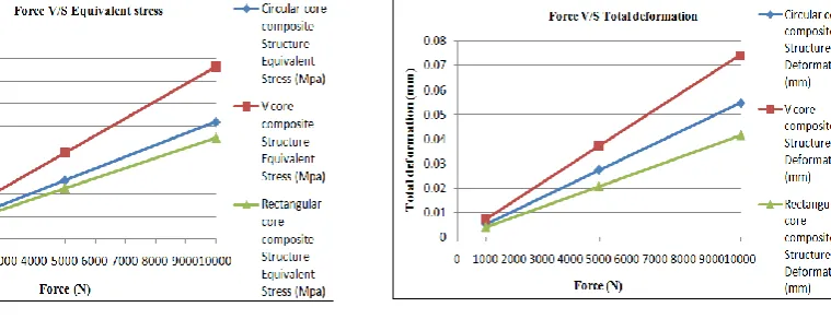
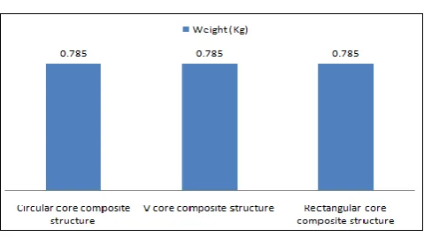
Fig. 4 Comparison graphs of total deformation, equivalent stress and weight of all composite structures. (a) Force V/S Equivalent stress of all composite structures. (b) Force V/S Total deformation of all composite structures. (c) Weight comparison of all composite structures.
Comparison graphs of total deformation, equivalent stress and weight shown in figures 4. From the graphs, it is observed that the equivalent stress and total deformation is minimum in rectangular core composite structure when compared with circular core composite structure and V core composite structure. At minimum force which is 1000N the equivalent stress in circular core composite structure and V core composite structure more than that of rectangular core composite structure. At minimum force which is 1000N the total deformation in circular core composite structure and V core composite structure more than that of rectangular core composite structure.
VI.CONCLUSION
The composite structure models in CATIA are efficiently imported into ANSYS workbench and structural analysis is done and equivalent stress and total deformation is observed. In rectangular core composite structure the strength increases and deflection decreases effectively as compare to circular core composite structure and V core composite structure. In rectangular core composite structure equivalent stress decreases by 13-41% and total deflection is a decrease to 23-44% as compare to circular core composite structure and V core composite structure.
REFERENCES
1. Kevin J. Doherty, Aristedes Yiournas, Jordan A. Wagner, and Yellapu Murty, “Structural Performance of Aluminum and Stainless Steel Pyramidal Truss Core Sandwich Panels” ,ARL-TR-4867 July 2009.
2. Aydıncak, İlke ” investigation of design and analyses principles of honeycomb structures” November 2007, 177 pages
3. Jukka Säynäjäkangas and Tero Taulavuori, Outokumpu Stainless Oy, Finland “A review in design and manufacturing of stainless steel sandwich panels” stainless steel world oktober 2004
4. Tomas Nordstrand, “Basic Testing And Strength Design Of Corrugated Board And Containers” Division of Structural Mechanics, LTH, Lund University, ISSN: 0281-6679, Box 118, SE-221 00 Lund, Sweden.
5. Pentti kujala, Alan Klanac,” Steel Sandwich Panels in Marine Applications” PrihvaÊeno, pp-305-314, 2005-05-05 6. Jani Romanoff “Bending Response of Laser- Welded Web-Core Sandwich Plates”ISSN (printed)1795-2239
7. Pentti Kujala “Steel Sandwich Panels – From Basic Research To Practical Applications” 2Vol. 16/ISSN 0784-6010 2002 8. Pentti kujala “ultimate strength analysis of all steel sandwich panels”Rakenteiden Makaniikka,vol.31 Nrot 1-2,1998,s. 32-45
9. Gopichand, Dr.G.Krishnaiah, B.Mahesh Krishna, Dr.Diwakar Reddy.V, A.V.N.L.Sharma “Design And Analysis Of Corrugated Steel Sandwich Structures Using Ansys Workbench”, International Journal of Engineering Research & Technology (IJERT) ISSN :2278-0181 Vol. 1 Issue 8, October – 2012.
BIOGRAPHY
Devendra B. Sonawane, Department of Mechanical Engineering, Siddhant college of Engineering, Pune, Maharashtra, India
Prof. R. N. Garad Assistant Professor, Department of Mechanical Engineering, Siddhant college of Engineering, Pune, Maharashtra, India