PERFORMANCE EVALUATION OF A MODEL
REFERENCE ADAPTIVE CONTROLLER (MRAC)
ONTWIN ROTOR MIMO SYSTEM
Sukumar Bera
1, Suman Singha Ray
2, Chanchal Dey
31,2
M.Tech Scholar,
2Assistant Professor, Department of Applied Physics,
University of Calcutta (India)
ABSTRACT
Twin rotor multi input multi output system (TRMS) is considered as a prototype laboratory set-up of helicopter, with significant cross coupling and nonlinearities. Such a plant is awell accepted benchmark system to test and explore modern control methodologies. In this paper we have designed and verified the performance of a model reference adaptive controller (MRAC) on a TRMS process. The performance of MRACduring tracking in vertical and horizontal planesis found to be quite satisfactory compared to conventional PID controller. Performance based analysis substantiates the superiority of MRAC technique during both tracking and load regulation phases.
Keywords: Model reference adaptive control, Modified MIT rule, Normalized algorithm, TRMS
process.
I. INTRODUCTION
Constant-gain feedback controllers proposed in early fiftiesfail to provide the better performance for the
different operating conditions in high performance aircrafts. Only adaptive controllers that could modify its own
behavior through parameter updationdepending on load variablesand variation in the aircraft dynamics are able
to offer acceptable performance. Model reference adaptive control (MRAC) technique is attempted [1] to solve
the autopilot design problem for high-performance aircraft.It is considered as an adaptive servo system in which
the desired performance is expressed in terms of reference model, which gives the desired response to a
command signal.Twin rotor multi input multi output system (TRMS) is considered to be a well-known
laboratory prototype with a significant cross coupling and nonlinearitiesfor realisingaero-dynamic behaviour of
a helicopter.
A numbers of control strategies [2-5]based on conventional and soft-computing approaches are available in
literature towards controlling the TRMS process.Ahybrid fuzzy PID controller is developedin [6] for achieving
improved responses from a TRMS process. Performance analysis reveals that fuzzy-PID controller reported in
[6] outperforms a conventional PID controller. The common difficult taskfor all the reported worksin controlling
dynamics, changes in environmental conditions and variation in thenature of the disturbances. As a result the
required controller must to be adaptive and robust to accommodate these changes.
To overcome the limitations of constant gain feedback controllers, this paper deals with the designing of a
MRAC scheme using the modified MIT rule [7]. Here, modified MIT rule is chosen for designing MRAC
[8-10]to make the controller insensitive to the changes in the amplitude of command signal. Performance of the
proposed MRAC scheme is compared with conventional PID controllerthrough simulation study based on a
number of performance indices. A brief description regarding TRMS process is given section 2. Design of
MRAC scheme is provided in section 3. Section 4 provides simulation results of theproposed MRAC in
comparison with PID controller. Responses along with performance indices during tracking and load rejection
phases substantiate the improved performance of MRAC in comparison with conventional PID controller.
Conclusion is given in section 5.
II.SYSTEM DESCRIPTION
TRMS processis considered as a model of a helicopter with some significant simplifications. The schematic
diagram for TRMS is shown in Fig. 1.The
TRMS process consists of a tower with a beam
attached by two bearings. These bearings allow
the beam to move freely in the horizontal and
vertical planes within some limits. At the two
ends of the beam, rotors are attached which are
shifted by from each other allowing them to
generate horizontal and vertical thrusts. The
main rotor and the tail rotor are used for varying
the pitch angle and yaw angle respectively. The
two rotors are placed on the opposite sides with
a counter balance in between. Counter balance is
used for proper balancing to the system. The whole unit is attached to a mechanical support to safely perform
experimental studies.
Dynamics of TRMS has two degrees of freedom - the rotors can rotate about a vertical and horizontal plane.
However, it can be transformedto 1DOF by locking either pitch or yaw whatever motion we want to control.The
electrical drive unit of TRMS placed under the support allows easy transfer of signals from the sensors to PC
and control signal from PC serial port to drive unit via DAQ card [11].
III.MODEL REFERENCE ADAPTIVE CONTROL (MRAC)
3.1Principle of MRAC
The general idea behind the model reference adaptive control (MRAC) [7, 12] is that to design a closed loop
controller with parameters which can be updated with thechange in response of the system. The output of the
model and actual process generates an error
signal which is used for continuous updating of
the controller parameters. Here, the goal is
targeted for the parameters to converge to the
ideal values that cause the plant response to
match the response obtained from the reference
model.
The basic block diagram of MRAC scheme is
shown in the Fig.2. It has an ordinary feedback
loop composed of the process and the controller
and another feedback loop that changes the
controller parameters. The parameters of the controller are altered by adjustment mechanism so that plant
response attempts to track the responses given by reference model. The algorithm for adjustment mechanismis
based on MIT rule. Here, we are using MIT rule with normalized algorithm and the technique is referred as
Modified MIT rule to make the controller behaviour independent of command signal amplitudes.
3.2 MIT rule
MRAC control strategy is obtained using gradient decent approach of MIT rule. According to the gradient
decent approach, a cost function is considered in terms of tracking error . Cost function is dependent
on where is the parameter that will be adapted to minimize the cost function.The tracking error is defined
as difference between the responses obtained from reference model and the plant to be controlled i.e.
The choice of cost function will determine how the parameters are updated. The typical cost function is given by
According to the MIT rule, rate of change of is directly proportional to negative gradient of cost function, as
shown in the following equation:
where = controller parameter vector, = adaptation gain and = sensitivity derivative. Sensitivity derivative
determines how the error is influenced by adjustable parameter . A controller may contain several
parameters that require updating.
There is no particular rule to choose the loss function. We can also choose and henceforth the
gradient method gives
But here we have chosen .
Fig. 2: Block diagram of MRAC.
Controller parameters
Adjustment mechanism
Plant Controller
3.3 Normalized algorithm
For large values of reference input, system may become unstable when the system is controlled by MRAC using
simple MIT rule because it is very sensitive to the changes in the amplitude of the commandsignal. Hence to
overcome this problem, normalized algorithm is used to the MIT rule to develop the control law.
Normalized algorithm modifies the adaptation law in the following manner,
Where and ( >0) is introduced to remove the difficulty of division by zero when is small.
Eq. (5) is also applicable during the conditions when there is more than one adjustable parameter. With the
above modifications using normalized algorithm, the adaptation law is referred as modified MIT rule [13].
Another important fact for designing MRAC is selection of an appropriate reference model. Normally, the
reference model is so selectedby the designer that it offers the desirableresponse from the system under all
possible operating conditions.
IV. SIMULATION RESULTS
In this paper, the MRAC technique is implemented for TRMS process in Matlab/Simulink environment.Initially,
we consider individual 1DOF model for vertical and horizontal motion of TRMS independently. Thereafter
2DOF model is chosen for TRMSprocess and its performance is studied in presence of decoupler [11].Here we
use a mixed sinusoidal signal with different frequencies as command signalfor pitch and
yaw . Initially controller performances are studied in absence of any external disturbance
and thereafterperformances are observed in presence of bothband-limited whitenoise andpulse nature
disturbances. To find out the effectiveness of MRAC, we have compared its performance with the conventional
PID controller.Performance of the reported controllers are evaluated and compared in terms of set point tracking
as well as disturbance rejection phases. The performance indices IAE (Integral Absolute Error), ITAE (Integral
Time Absolute Error), and TV (Total
Variation of control signal) are
computed for each setting. Lesser value
of performance indices justifiesthe
superiority of MRAC scheme in
comparison with PID controller as
reported in following Tables I-II.
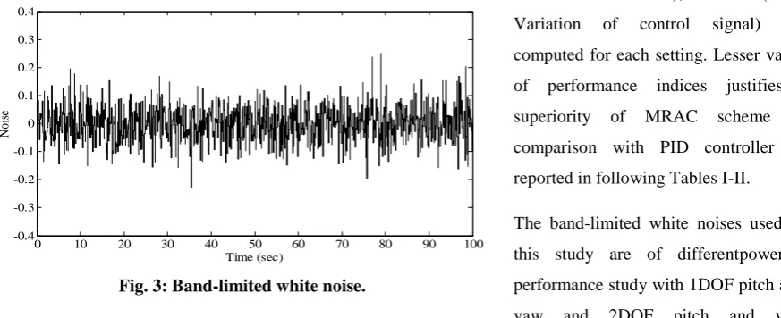
The band-limited white noises used in
this study are of differentpowersin
performance study with 1DOF pitch and
yaw and 2DOF pitch and yaw
dynamics. Fig. 3 shows a white noise signal with noise power 0.04 and variance 0.01 used in simulation study
for TRMS process.
0 10 20 30 40 50 60 70 80 90 100
-0.4 -0.3 -0.2 -0.1 0 0.1 0.2 0.3 0.4
Time (sec)
N
o
is
e
4.1Comparative study during tracking phase
4.1.1 1DOF pitch response
Comparative performances between MRAC and PID controller for controlling only pitch motion i.e., 1DOF
responses during tracking of TRMS in shown Fig.4 and Fig.5 respectively.
0 10 20 30 40 50 60 70 80 90 100
0 0.1 0.2 0.3 0.4 0.5 0.6 0.7 0.8 Time (sec) P it ch a n g le (r ad ) Model Response MRAC Response
0 10 20 30 40 50 60 70 80 90 100
0 0.1 0.2 0.3 0.4 0.5 0.6 0.7 0.8 Time (sec) P it c h a n g le ( ra d )
elevation - pitch
Command Signal PID Response
Fig. 4: MRAC response for 1DOF pitch. Fig. 5: PID response for 1DOF pitch. 4.1.2 1DOF yaw response
Responsesof MRAC and PID controllers for controlling only yaw motioni.e. 1DOF responses of TRMS is
shown in Fig.6 and Fig.7 respectively.
0 10 20 30 40 50 60 70 80 90 100
0.5 1 1.5 2 2.5 3 3.5 4 Time (sec) Y aw a n g le ( ra d ) Model Response MRAC Response
0 10 20 30 40 50 60 70 80 90 100
0.5 1 1.5 2 2.5 3 3.5 4 Time (sec) Y aw a n g le ( ra d )
azimuth - yaw
Command Signal PID Response
Fig.6: MRAC response for 1DOF yaw. Fig.7: PID response for 1DOF yaw. 4.1.3 2DOF pitch response
Responses of MRAC and PID controllers for controlling 2DOF pitch motion of TRMS is shown in Fig.8 and
Fig.9 respectively.
0 10 20 30 40 50 60 70 80 90 100
-0.2 0 0.2 0.4 0.6 0.8 1 1.2 Time (sec) P it ch a n g le ( ra d ) Model Response MRAC Response
0 10 20 30 40 50 60 70 80 90 100
-0.2 0 0.2 0.4 0.6 0.8 1 1.2 Time (sec) P it ch a n g le ( ra d )
elevation - pitch
Command Signal PID Response
Fig.8: MRAC response for 2DOF pitch. Fig.9: PID response for 2DOF pitch.
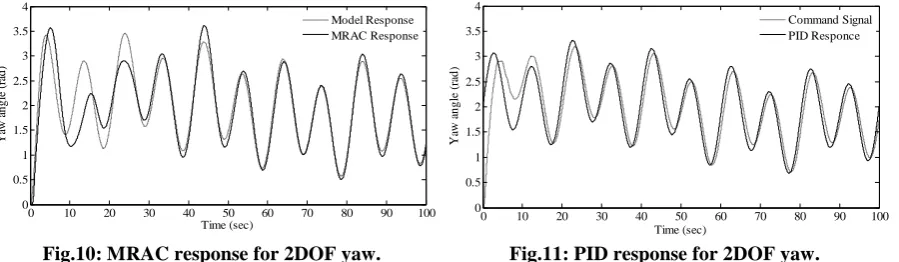
4.1.4 2DOF yaw response
Responses of MRAC and PID controllers for controlling 2DOF yaw motion of TRMS is shown in Fig.10 and
0 10 20 30 40 50 60 70 80 90 100 0 0.5 1 1.5 2 2.5 3 3.5 4 Time (sec) Y aw a n g le ( ra d ) Model Response MRAC Response
0 10 20 30 40 50 60 70 80 90 100
0 0.5 1 1.5 2 2.5 3 3.5 4 Time (sec) Y aw a n g le ( ra d )
azimuth - yaw
Command Signal PID Responce
Fig.10: MRAC response for 2DOF yaw. Fig.11: PID response for 2DOF yaw.
For having a clear comparison among the reported controllers in addition to response the values of performance
indices (IAE, ITAE and TV) for MRAC and PID controllers are depicted in Table 1.
Table I
4.2 Performance analysis during tracking in presence of white noise and disturbance
4.2.1 1DOF pitch response
Comparative study between MRAC and PID controller for controlling only pitch motion of TRMS in presence
of white noise and disturbancesis shown in Fig.12 and Fig.13 respectively. Whitenoise power is 0.001and
variance is 0.01. The pulse like disturbances are given at time 50-52s and 70-72s.
0 10 20 30 40 50 60 70 80 90 100
0 0.1 0.2 0.3 0.4 0.5 0.6 0.7 0.8 Time (sec) P it ch a n g le ( ra d ) Model Response MRAC Response
0 10 20 30 40 50 60 70 80 90 100
0 0.1 0.2 0.3 0.4 0.5 0.6 0.7 0.8 Time (sec) P it ch a n g le ( ra d )
elevation - pitch
Command Signal PID Response
Fig.12: MRAC response for 1DOF pitch in presenceof white noise and disturbance.
Fig.13: PID response for 1DOF pitch in presence of white noise and disturbance.
4.2.2 1DOF yaw response
Performances of MRAC and PID controllers for controlling only yaw motion of TRMS in presence of white
noise and external disturbancesareshown in Fig.14 and Fig.15. Whitenoise power is 0.04 and variance is0.01
TRMS Dynamics
IAE ITAE TV
PID MRAC PID MRAC PID MRAC
1DOF pitch 3.23 2.12 115.70 67.76 0.70 0.20
1DOF yaw 23.84 17.27 866.90 316.10 0.83 0.50
2DOF pitch 5.31 3.41 224.30 83.72 4.07 0.76
0 10 20 30 40 50 60 70 80 90 100 0.5 1 1.5 2 2.5 3 3.5 4 Time (sec) Y aw a n g le ( ra d ) Model Response MRAC Response
0 10 20 30 40 50 60 70 80 90 100
0.5 1 1.5 2 2.5 3 3.5 4 Time (sec) Y aw a n g le (r ad )
azimuth - yaw
Command Signal PID Response
Fig.14: MRAC response for 1DOF yaw in presence of white noise and disturbance.
Fig.15: PID response for 1DOF yaw in presence of white noise and disturbance.
4.2.3 2DOF pitch response
Similar to previous study, responses of MRAC and PID controllers for controlling 2DOF pitch motion of
TRMS in the presence of white noise and disturbancesis shown in Fig.16 and Fig.17. Whitenoise power is 0.005
and variance is 0.01. Pulse natureexternal disturbanceis given at time 55-57s.
0 10 20 30 40 50 60 70 80 90 100
-0.2 0 0.2 0.4 0.6 0.8 1 1.2 Time (sec) P it ch a n g le ( ra d ) Model Response MRAC Response
0 10 20 30 40 50 60 70 80 90 100
-0.2 0 0.2 0.4 0.6 0.8 1 1.2 Time (sec) P it ch a n g le ( ra d )
elevation - pitch
Command Signal PID Response
Fig.16: MRAC response for 2DOF pitch in presenceof white noise and disturbance.
Fig.17: PID response for 2DOF pitch in presence of white noise and disturbance.
4.2.4 2DOF yaw response
Comparative study between MRAC and PID controllers for controlling 2DOF yaw motion of TRMS in the
presence of white noise and disturbancesare shown in Fig.18 and Fig.19 respectively. Whitenoise power is 0.04
and variance is 0.01. The disturbance given at time 55-57s.
0 10 20 30 40 50 60 70 80 90 100
-1 0 1 2 3 4 Time (sec) Y aw a n g le ( ra d ) Model Response MRAC Response
0 10 20 30 40 50 60 70 80 90 100
-0.5 0 0.5 1 1.5 2 2.5 3 3.5 4 Time (sec) Y a w a n g le ( ra d )
azimuth - yaw
PID Response Command Signal
Fig.18: MRAC response for 2DOF yaw in presence of white noise and disturbance.
For a clear comparison between MRAC and PID controllers, values of the performance indices (IAE, ITAE and
TV) for respective controllers are shown in the Table II.
Table II
The related tuning parameters used for MRAC are given in Table III.
Table III
V. CONCLUSION
In this paper, model reference adaptive control scheme for controlling the pitch and yaw motions of
TRMSprocess is reported. This controlling methodshows better adaptation capability when compared with the
conventional fixed gain PIDmethod in terms of IAE and ITAE values. Moreover, it is also found in most of the
cases improved responses from MRAC are obtained at a lesser TV values compared to PID. It is also seen from
the results that MRAC provides much better results for 1DOF pitch and 1DOF yaw responses compared to PID
when noise and disturbance are introduced to the system. Similarly, for 2DOF pitch and yaw responses MRAC
also shows satisfactory results compared to PID in presence of noise and disturbance.In future fuzzy rule based
inference can be used to select more appropriate values of variable adaptation gains compared to their fixed
values so that an overall improved responses can be obtained.
REFERENCES
[1] H. P. Whitaker, J. Yamron and A. Kezer, Design of MRAC system for aircraft, Report no.
R-TRMS Dynamics IAE ITAE TV
PID MRAC PID MRAC PID MRAC
1DOF pitch 4.75 3.93 208.20 179.30 2.89 2.69
1DOF yaw 25.94 22.55 1010.00 639.90 848.10 635.60
2DOF pitch 7.23 6.22 333.10 240.50 10.29 4.31
2DOF yaw 27.23 26.76 1103.00 1055.00 10.34 77.31
TRMS Dynamics MRAC constant values MRAC adaptation gains
1DOF pitch 0.001 1.0 -1.9 0.8
1DOF yaw 1.2 1.2 -1.0 1.0
2DOF pitch 0.1 1.0 -1.9 1.4
[2] S. M. Ahmad, A. J. Chipperfield, and M. O. Tokhi, Dynamic modelling and control of a 2 DOF twin
rotor multi-input multi-output system, Proc. of Conf. ofIEEE Industrial Electronics Society, Nagoya,
Japan, 2000, 451–456.
[3] S. Mondal and C. Mahanta, Adaptive second-order sliding mode controller for a twin rotor multi-input–
multi-output system, IET Control Theory & Applications, 6(14), 2012, 2157–2167.
[4] A. Bayrak, M. H. Salah, N. Nath, and E. Tatlicioglu, Neural network-based nonlinear control design for
twin rotor MIMO systems. In Proc. of Int. Symposiumon Mechanism and Machine Science, Izmir,
Turkey, 2010, 172–178.
[5] P. Biswas, R. Maity, A. Kolay, K. D. Sharma and G. Sarkar, PSO Based PID Controller Design for Twin
Rotor MIMO System, International Conference on Control, Instrumentation Energy and Communication
(CIEC), 2014, 106-110.
[6] A. Rahidehand M. H. Shaheed, Hybrid fuzzy-PID-based control of a twin rotor MIMO system, in
Proceedings of the 32nd Annual Conference on IEEE Industrial Electronics (IECON ’06), 2006, 49–54.
[7] K. J.Astrom and B. Wittenmark, Adaptive control, (2nd ed., Dover Publications, New York, 2001).
[8] P. Swarnkar, S. K. Jain and R. K. Nema, Effect of adaptation gain on system performance for model
reference adaptive control scheme using MIT rule. International Conference of World Academy of
Science, Engineering and Technology, Paris, 2010, 70-75.
[9] M. S. Ehsani, Adaptive Control of Servo Motor by MRAC Method, IEEE International Conference on
Vehicle, Power and Propulsion, Arlington, 2007, 78 – 83.
[10] M. Kirar, P. Swarnkar, S. Jain and R. K. Nema, Comparative Study of Conventional and Adaptive
Schemes for DC Servomotors, International Conference on Energy Engineering ICEE, Puducherry, India,
2009.
[11] Twin Rotor MIMO System Manual, (Feedback Instruments Ltd. U. K. 33-949S, 2002).
[12] S. R. Kolapalli, Study of Discrete time Model Reference Adaptive Control Using Kalman Filter,
Jadavpur University,Kolkata, M. Tech, 2010.
[13] P. Jain and M.J. Nigam, Design of a Model Reference Adaptive Controller Using Modified MIT Rule for
a Second Order System, Advance in Electronic and Electric Engineering.ISSN 2231-1297, 3(4), 2013,