* Corresponding author: [email protected]
Recent progress on improving ICRF coupling and reducing
RF-specific impurities in ASDEX Upgrade
Wei Zhang1,2,3*, Volodymyr Bobkov1, Jean-Marie Noterdaeme1,2, Wouter Tierens1, Diogo Aguiam4, Roberto Bilato1, David Coster1, Laurent Colas5, Kristel Crombé2,6, Helmut Fuenfgelder1, Helmut Faugel1, Yuhe Feng7, Jonathan Jacquot1, Philippe Jacquet8, Arne Kallenbach1, Ana Kostic1,2, Tilmann Lunt1, Riccardo Maggiora9, Roman Ochoukov1, Antonio Silva4, Guillermo Suárez1, Angelo A. Tuccilo10, Onofrio Tudisco10, Mariia Usoltceva1,2, Dirk Van Eester6, Yongsheng Wang3, Qingxi Yang3, the ASDEX Upgrade Team1 and the EUROfusion MST1 Team11
1Max-Planck-Institut für Plasmaphysik, Garching, Germany 2Applied Physics Department, University of Ghent, Ghent, Belgium
3Institute of Plasma Physics, Chinese Academy of Sciences, Hefei, P. R. China 4Instituto de Plasmas e Fusão Nuclear, IST, Universidade de Lisboa, Portugal 5CEA, IRFM, F-13108 Saint-Paul-Lez-Durance, France
6Laboratory for Plasma Physics, ERM/KMS, Brussels, Belgium 7Max-Planck-Institut für Plasmaphysik, Greifswald, Germany 8CCFE, Culham Science Centre, Abingdon, UK 9Politecnico di Torino, Torino, Italy
10ENEA, Fusion Physics Division, Frascati, Italy
Abstract. The recent scientific research on ASDEX Upgrade (AUG) has greatly advanced solutions to two issues of Radio Frequency (RF) heating in the Ion Cyclotron Range of Frequencies (ICRF): (a) the coupling of ICRF power to the plasma is significantly improved by density tailoring with local gas puffing; (b) the release of RF-specific impurities is significantly reduced by minimizing the RF near field with 3-strap antennas. This paper summarizes the applied methods and reviews the associated achievements.
1 Introduction
The coupling of Radio Frequency (RF) power in the Ion Cyclotron Range of Frequencies (ICRF) to the plasma depends sensitively on the Scrape-Off Layer (SOL) density because the fast wave is evanescent below the cut-off density (typically in the order of 1018 𝑚𝑚−3 in nowadays tokamaks). The ICRF power coupling can be greatly enhanced by increasing the density in front of the antennas with local gas puffing. In ASDEX Upgrade (AUG) tokamak, it is found that compared to divertor gas puffing, midplane gas puffing close to the antennas increases the ICRF power coupling most significantly and top gas puffing increases it in a smaller level. The 3D edge plasma fluid and neutral transport code EMC3-EIRENE [1] is used to model the SOL density during different gas puffing scenarios in AUG. Antenna codes such as FELICE [2], TOPICA [3] and RAPLICASOL [4] are then used to calculate the antenna coupling resistance. Good agreement is found between the simulation and experimental results [5, 6].
Among the effects responsible for RF-specific impurity generation, the RF sheaths induced by the near-field effects have been found to be dominant in AUG so far [7, 8]. The RF enhanced sheath potential can be attributed to the image current driven on the antenna
box. The novel 3-strap antennas, recently installed in AUG [9], has been designed to reduce those undesired currents through adjusting properly the phase and amplitude of the current in the straps. The recent results have shown that compared to 2-strap antennas, the use of 3-strap antennas reduces the RF-specific tungsten release significantly [10]. The SOL density convection due to the inhomogeneous RF-sheath potential was measured with poloidally distributed reflectometers embedded in one 3-strap antenna [11]. The measured density convection can clearly be reproduced in the self-consistent simulations by running the EMC3-EIRENE, RAPLICASOL and SSWICH [12] codes in an iterative way [13]. Progress of these studies are reviewed in the paper.
2 Improvement of ICRF coupling
from the divertor to the main chamber. The core plasma propertites were kept close to identical during different gas puffing schemes.
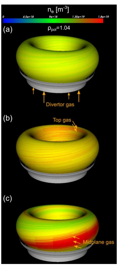
Fig. 1. 3D electron density in AUG during (a) divertor gas puffing; (b) top gas puffing; (c) midplane gas puffing. The densities are plotted on the same flux surface. The same gas puff rate is used (1.2 × 10²² 𝑒𝑒𝑒𝑒/𝑠𝑠) and the gas puffing
locations and directions are indicated by the arrows.
Here, the EMC3-EIRENE code is used to calculate the SOL plasma density in the presence of different gas sources. A toroidal 360o grid with high resolution in the
SOL is used. All the plasma facing components as well as the realistic gas source positions are taken into account. Moreover, the SOL plasma parameters, such as the upstream density and temperature profiles and the
downstream power and particle fluxes, are fitted to the experimental ones by choosing appropriate particle and energy transport coefficients [5, 6]. SOL boundary conditions, such as the separatrix density and power across the separatrix, are set the same as those in the experiments. No impurity is considered in the simulations and the part of power radiated by impurities is subtracted from the total heating power.
An example of the simulated SOL electron densities during divertor, top and midplane gas puffing is shown in Fig. 1. Compared to divertor gas puffing (reference case), top gas puffing increases the SOL density almost uniformly toroidally, but to a small extent; midplane gas puffing increases the SOL density very significantly and locally. The density profiles measured by the reflectometry at particular toroidal positions are in good agreement with those in simulations [5, 6]. The increase of the local density leads to a shift of the fast wave cut-off density layer towards the vessel. This shift is ~0.7cm during top gas puffing and can locally be up to about 2.0cm close to the gas valve during midplane gas puffing. The shift of the fast wave cut-off density layer decreases the width of evanescence layer and increases the ICRF power coupling.
The mechanisms of the local density increase by local gas puffing are summarized as follows. Firstly, a localized neutral gas cloud developes in front of the top or midplane gas valve. Due to ionization (𝑇𝑇𝑒𝑒>2eV), a
localized high plasma density cloud develops in the SOL. Charged particles in this high density cloud transport very quickly along the magnetic field lines with a consequent increase of the density in the regions magnetically connected with the valves. Field lines starting from the top density cloud towards the midplane spread widely and lead to an evenly increased SOL density. Field lines starting from the midplane density cloud are much more concentrated and result in a localized density increase. Additionally, the plasma temperature at the locations of the density cloud are lowered, because the outward plasma flows (particle convection) and ionization provide energy sinks. The plasma pressure (density×temperature) along the same flux tubes are the same, thus density gradients develop along the same flux tubes. The largest density is expected to be at location where the ionization is largest.
(decay length ~3.7m) as the distance between the antenna and the gas valve becomes larger.
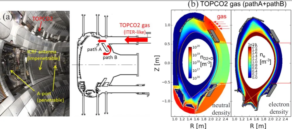
The previously discussed top gas sources are located at the inner top of the vessel. In addition, we have studied the outer top gas puffing (TOPCO2) in AUG L-mode plasmas [6]. This gas puffing is more ITER relevant, because in ITER the fueling gas is planned to be puffed from the outer top positions. The distribution of this gas depends on the surrounding wall structures and is different in different machines. In AUG, the outer top gas enters the plasma either through the top windows (path A) or through the A-ports in the midplane (path B), Fig. 2(a). It is shown that a localized neutral cloud is developed in the top while a more homogenous one is formed in the midplane, Fig. 2(b).
The calculated relative increase of coupling resistances with the RAPLICASOL code is in quantitative agreement with the experimental values shown in Fig 3. The largest increase of coupling resistance is ~70% in
L-mode plasmas with midplane gas puffing (gas puff rate ~6.5 × 10²¹ 𝑒𝑒𝑒𝑒/𝑠𝑠). As for the outer top gas puffing (ITER releveant), the experimental results are in better agreement with simulations when only path B is assumed to be open (i.e. with the part of gas clouds only in the midplane). The antenna closest to the gas valve has the largest coupling resistance increase and this increase decays with the gas valve - antenna distance. Considering the fact that about half of the injected gas passes through path A and the corresponding gas cloud in the top is magnetically connected to antenna in sector 10 (with a gas valve – antenna distance ~5.4m), the effect of the localized high neutral density on the local increase of plasma density plays a more important role than the effect of field line connections. Indeed, in the simulations the top gas cloud associated with path A increases the SOL density in a much more toroidal uniform way [6].
From our previous studies, we conclude that the poloidal distributed gas valves close to the ICRF
(b)
(a)
Fig 2. (a) Outer top gas puffing (TOPCO2, ITER relevant) and the surrounding wall structures in AUG; (b) neutral and electron density during outer top gas puffing. Figure reproduced with permission from [6].
(a) Experiments
(b) Simulations
Fig. 3. Relative increase of coupling resistance ∆𝑅𝑅𝑐𝑐 𝑅𝑅𝑐𝑐_𝑟𝑟𝑟𝑟𝑟𝑟 obtained from (a) experiments; (b) simulations with the EMC3-EIRENE
and RAPLICASOL codes. Figure reproduced with permission from [6]. The whole AUG torus has 16 sectors toroidally. “Midplane sec. 13” and “Midplane sec. 3” represent midplane gas puffing in sector 13 and sector 3, respectively.
neutral
antennas are the best option to maximize the ICRF power coupling. This conclusion is also expected to be valid for future machines such as ITER and DEMO.
An additional benefit of local gas puffing is the reduction of total outer wall sputtering and core W concentration [17]. This is attributed to the local decrease of plasma temperature in the far SOL and the decrease of sheath potential in front of the antennas during local gas puffing. Future investigations are underway to understand the mechanisms. Furthermore, the influence of magnetic perturbation fields and MHD modes on the SOL density and thus on the ICRF coupling properties is now being studied [22]. Possible synergies with gas puffing will also be addressed in the future.
3 Reduce RF-specific impurities
ICRF antennas excite fast wave via oscillating currents on the radiating straps. However, the oscillating currents induce image currents on the antenna box accompanied by 𝐸𝐸∥ fields (parallel to the equilibrium magnetic field)
in the vicinity of the antennas. Subsequently, an increase of sheath potential is driven by the 𝐸𝐸∥ fields. The large
potential drop across the sheath accelerates ions towards the wall, leading to considerable physical sputtering and even to hot spots if the impacting ions are energetic enough. The hot spots can damage the wall components and the impurities induced by sputtering can affect the plasma performances. In AUG (full tungsten (W) wall), substantial impurity radiation losses can be generated if the W concentration (𝑐𝑐𝑊𝑊) in the plasma core exceeds
5 × 10⁻⁵ [7].
The recent research activities in AUG have made significant progress in reducing the ICRF-induced impurities. The first strategy is to coat the antenna limiters with a low-Z material boron (B) instead of W since experiments suggest that the major ICRF-induced W sources are from the antenna limiters [18]. In 2012,
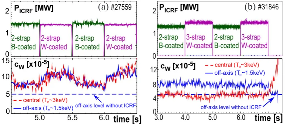
limiters of two antennas were coated with boron. The experimental results (Fig. 4(a)) clearly show that a reduction of RF-induced fraction of W concentration by a factor of two both in the edge and central plasma has been achieved with B-coated 2-strap antennas. The antenna limiters account for more than half of the increase in W concentration during ICRF heating. In these experiments, a standard H minority scheme with dipole phasing was used. The shifting of sputtering from tungsten to boron is less problematic since the boron content in the core plasma is more tolerable and causes less power radiation. The B-coated antennas allow the ICRF heating to operate in a wider range of plasma conditions. However, the B-coating is only a remedy to the high-Z impurity production induced by ICRF and not a solution of the problem associated with the RF fields close to the antenna.
The long-term strategy to reduce the ICRF-specific impurities involves optimizing the antenna design so that the generated image currents and 𝐸𝐸∥ fields at antenna
limiters are minimized. One of the strategies was to use broad-limiter antennas. The release of W was reduced by up to ~40% in a single antenna operation in experiments operated with broad-limiter antennas [7]. The other more advanced approach is the design and use of 3-strap antennas in AUG. The basic idea of this approach is to minimize the RF image currents on the antenna limiters by balancing the dipole contributions of the central strap with that of the outer straps [10]. In 2015, a pair of W-coated 3-strap antennas has been installed in ASDEX Upgrade. The experimental results (Fig. 4(b)) show that the W-coated 3-strap antennas lead to almost the same values of edge and core W concentration as those for the B-coated 2-strap antennas. The heating effectiveness of the W-coated 3-strap antenna is not lower than that of B-coated 2-strap [10] while the ICRF heating power, plasma current, total input and radiated power are almost the same in the studied discharge. Together with the previous results (Fig4. (a)), we can conclude that the use of W-coated 3-strap antennas reduces the RF-induced Fig. 4. Central and edge W concentrations during ICRF heating with (a) B-coated and W-coated 2-strap antennas; (b) B-coated 2-strap and W-coated 3-strap antennas. Figure reproduced with permission from [7, 10].
fraction of W concentration also by at least a factor of two compared to the W-coated 2-strap antennas.
A prominent rise of core W concentration after switching the ICRF power off (Fig. 4 (b)) is due to changes in the neoclassical transport of W. During ICRF heating, the core plasma density profiles are flattened and the core plasma temperature profiles are peaked. The flattening of density leads to reduced density gradients and thus reduced inward W transport while the peaking of temperature leads to increased temperature gradients and thus increased outward W transport [19]. As a result the core W concentration during ICRF heating is much lower than that without.
The final W concentration and W sputtering yield depend on the 3-strap antenna feeding configurations, including the phasing and power ratio between the central and outer straps (𝑃𝑃𝑐𝑐𝑐𝑐𝑐𝑐 𝑃𝑃𝑜𝑜𝑜𝑜𝑜𝑜, where 𝑃𝑃𝑐𝑐𝑐𝑐𝑐𝑐 is the power on the central strap and 𝑃𝑃𝑜𝑜𝑜𝑜𝑜𝑜 is the total power on the two outer straps, respectively). The lowest W concentration and the lowest W sputtering yield on the antenna limiters were observed with dipole phasing and 𝑃𝑃𝑐𝑐𝑐𝑐𝑐𝑐 𝑃𝑃𝑜𝑜𝑜𝑜𝑜𝑜 in the range (1.5, 2.0) [10]. Non-optimized feeding configurations cause high image currents and W sputtering yield. An example of this is shown in Fig. 5, in which large unbalanced image currents on the antenna limiters and 𝐸𝐸∥ fields in front of the antenna limiters (calculated by TOPICA [3]) are generated when 𝑃𝑃𝑐𝑐𝑐𝑐𝑐𝑐 𝑃𝑃𝑜𝑜𝑜𝑜𝑜𝑜 is too small (case (a)) or too large (case (c), see [23] for more details). Numerical simulations show that the 3-strap antenna even with non-optimized settings (i.e. dipole phasing, 𝑃𝑃𝑐𝑐𝑐𝑐𝑐𝑐 𝑃𝑃𝑜𝑜𝑜𝑜𝑜𝑜 ~ 9) generates 𝐸𝐸∥ fields and sheath potential which are smaller than those due to the 2-strap antenna with typical feeding configurations (i.e. dipole phasing, 𝑃𝑃𝑐𝑐𝑐𝑐𝑐𝑐 𝑃𝑃𝑜𝑜𝑜𝑜𝑜𝑜= 1) [13].
Further experiments show that the local measurements of RF voltages at the shunts at the side limiters of one 3-strap antenna correlate with the measured W sputtering yield [8]. The calculated local 𝐸𝐸∥ fields by TOPICA at the same locations are qualitatively consistent with the measured RF voltages [8]. These findings provide evidence for links between the 𝐸𝐸∥ fields, RF voltages and W sputtering yield.
The number of sputtered impurities not only depend on the sputtering yield but also on the number of impacting particles, i.e. on the local plasma density in the far SOL. E×B drifts driven by the inhomogenous sheath potential will however influence this local plasma density. Recently, progress has been made on understanding the ICRF induced density convection in the SOL from two numerical approaches [13, 20]: (a) EMC3-EIRENE simulations based on the measured potential; (b) Self-consistent simulations with several codes including EMC3-EIRENE, RAPLICASOL and SSWICH. In the first approach, the E×B drifts are calculated from the measured potentials and are then used as prescribed drifts in EMC3-EIRENE. In the second approach, the output of EMC3-EIRENE (plasma density) is used as inputs in RAPLICASOL and SSWICH, the output of RAPLICASOL (the 𝐸𝐸∥ fields) are used as inputs in SSWICH and the output of SSWICH (sheath potential) is used to calculate the E×B drifts, which are then used as inputs in the EMC3-EIRENE code. The obtained results from these simulations are in agreement [20] or consistent [13] with the corresponding measurements.
4 Conclusions
This paper summarizes the recent progress of ICRF heating in ASDEX Upgrade tokamak on two aspects:
(a)
P
cen/ P
out= 0.1
I
RFI
RFI
RF(c)
P
cen/ P
out= 10
(b)
P
cen/ P
out= 2
Fig. 5. Schematic image currents and parallel electric field calculated by TOPICA [3] in the vacuum gap 2 mm in front of limiters of 3-strap antenna, with power balance of (a) 𝑃𝑃𝑐𝑐𝑐𝑐𝑐𝑐 𝑃𝑃𝑜𝑜𝑜𝑜𝑜𝑜= 0.1; (b) 𝑃𝑃𝑐𝑐𝑐𝑐𝑐𝑐 𝑃𝑃𝑜𝑜𝑜𝑜𝑜𝑜= 2; (c) 𝑃𝑃𝑐𝑐𝑐𝑐𝑐𝑐 𝑃𝑃𝑜𝑜𝑜𝑜𝑜𝑜= 10. In these cases
improving the ICRF power coupling and reducing the ICRF-specific impurities.
The ICRF power coupling is improved by increasing the local density in front of the antennas with local deuterium gas puffing. Compared to divertor gas puffing, midplane gas puffing close to the ICRF antenna increases the ICRF power coupling most significantly (~120%) while top gas puffing increases it to a much smaller level (~25%) [5]. The effects of local gas puffing on local plasma density are attributed to the local high neutral density, magnetic filed line connections and the local decrease of temperature [5, 21]. It can be extrapolated that for future machines, such as ITER and DEMO, local gas valves close to the antennas are the best option in terms of maximizing ICRF power coupling.
The tungsten concentration in the central and edge plasma was reduced by using one of the three antenna modifications: (1) the broad-limiter antenna (up to ~40% for single antenna operation) [7]; (2) the boron-coated antennas (by about a factor of 2) [7]; (3) the 3-strap antennas (by more than a factor of 2) [10]. The tungsten sources, especially those from the antenna limiters are reduced either by replacing the tungsten sputtering by sputtering of a low-Z material (boron-coated antennas) or by decreasing the image currents on the antenna limiters (broad-limiter or 3-strap antennas). The latter solution is the most promising one, because it reduces the image currents and the parallel electric field most significantly. When operating the 3-strap antenna with dipole phasing and a power ratio between the central and outer straps in the range (1.5, 2.0), tungsten sputtering at the antenna limiters is minimized [10]. Further experiments and simulations show that the RF voltages measured on the antenna limiters correlate with the measured tungsten effective sputtering yield and are consistent with the calculated local parallel electric field at the antenna limiters [8].
Following the previous achievement, EMC3-EIRENE simulations for ITER and DEMO are being carried out to find the optimized gas puff locations and gas puff rate for the best ICRF power coupling. Theoretical approaches [24-26] to model sheaths are being developed and will be validated against measurements on ASDEX Upgrade [11, 27] and on IShTAR [28, 29]. Theoretical insight of experimental results will provide key guidelines to design antennas with reduced sheaths and RF-induced impurities.
This work has been carried out within the framework of the EUROfusion Consortium and has received funding from the Euratom research and training programme 2014-2018 under grant agreement No 633053. The views and opinions expressed herein do not necessarily reflect
those of the European Commission.
References
[1] Feng Y. et al 2004 Contributions to Plasma Physics
44 57-69
[2] Brambilla M. 1989 Plasma Physics and Controlled Fusion 31 723-57
[3] Lancellotti V. et al 2006 Nuclear Fusion 46 S476-S99
[4] Jacquot J. et al 2015 AIP Conference Proceedings
1689 050008
[5] Zhang W. et al 2016 Nuclear Fusion 56 036007 [6] Zhang W. et al 2017 Plasma Phys. Control. Fusion
59 075004
[7] Bobkov V. et al 2013 Nuclear Fusion 53 093018 [8] Bobkov V. et al 2017 Plasma Phys. Control. Fusion
59 014022
[9] Fuenfgelder H. et al 2017 Fusion Engineering and Design, "A double success story: The international cooperation to built the new ICRF antennas on ASDEX Upgrade and the results obtained",
http://dx.doi.org/10.1016/j.fusengdes.2017.03.114 [10] Bobkov V. et al 2016 Nuclear Fusion 56 084001 [11] Aguiam D. E. et al 2016 Review of Scientific Instruments 87 11E722
[12] Jacquot J. et al 2014 Physics of Plasmas 21 061509 [13] Zhang W. et al 2017 Nuclear Fusion 57 116048 [14] Bobkov V. et al 2014 AIP Conference Proceedings
1580 271
[15] Zhang W. et al 2015 AIP Conference Proceedings
1689 050006
[16] Jacquet P. et al 2016 Nuclear Fusion 56 046001 [17] Bobkov V. et al 2015 AIP Conference Proceedings
1689 030004
[18] Bobkov V. et al 2011 Journal of Nuclear Materials
415 S1005-S8
[19] Neu R. et al 2007 Plasma Physics and Controlled Fusion 49 B59-B70
[20] Zhang W. et al 2016 Plasma Phys. Control. Fusion
58 095005
[21] Zhang W. et al 2017 Nuclear Fusion 57 056042 [22] Suárez G. et al, " Investigation of the coupling properties of the Ion Cyclotron Fast Wave under applied Magnetic Perturbations and MHD Phenomena in ASDEX Upgrade", this conference, C-28
[23] Bobkov V. et al, “Characterization of 3-strap antennas in ASDEX Upgrade”, this conference, C-29 [24] Tierens W. et al, “3-Dimensional density profiles in edge plasma simulations for ICRF heating”, this conference, A-25
[25] Jacquot J. et al, "Sequential modelling of ICRF wave coupling and self-consistent RF sheaths description for AUG ICRF antennas", this conference, B-39
[26] Zhang W. et al, "Plasma edge modelling with ICRF coupling", this conference, C-05
[27] Ochoukov R. et al, "Latest upgrades of the high frequency B-dot probe diagnostic suite on ASDEX Upgrade", this conference, A-38
[28] Kostic A. et al, "Feasibility study of Passive Optical Emission Spectroscopy for the electric field measurements in IShTAR", this conference, C-42
![Fig. 5. Schematic image currents and parallel electric field calculated by TOPICA [3] in the vacuum gap 2 mm in front of limiters of 3-strap antenna, with power balance of (a) dipole phasing is used](https://thumb-us.123doks.com/thumbv2/123dok_us/8128649.1354587/5.595.50.549.58.298/schematic-currents-parallel-electric-calculated-limiters-antenna-balance.webp)
