BEXCO, Busan, Korea - August 20-25, 2017 Division V
DIRECT METHOD AND MODIFIED SUBTRACTION METHOD FOR
INCOHERENT SSI ANALYSIS OF AN EMBEDDED NUCLEAR ISLAND
STRUCTURE
Dongyi Yue1, Michael Donohoe2, Aly Mohammad3, and Anthony Crincoli4
1
Technical Leader, AECOM, Piscataway, NJ, USA ([email protected])
2
Structural Analyst, AECOM, Princeton, NJ, USA
3
Vice President, AECOM, New York, NY, USA
4
Associate Vice President, AECOM, Piscataway, NJ, USA
ABSTRACT
This paper presents results of a comparison study for the application of the Direct Method (DM) and the Modified Subtraction Method (MSM) to the seismic soil-structure interaction (SSI) analysis of an embedded nuclear island (NI) structure considering both the effects of spatial incoherence of the ground input motions and the foundation embedment. The procedures of the DM and MSM for deterministic incoherent SSI analysis are developed and implemented in a SASSI program. The study is performed on a full finite element model of the NI structure with a generic rock site profile and high frequency content rich input motions. Based on the finite element discretization of the excavated soil volume, the eigen solutions of specified ground motion coherency matrix are evaluated and used in conjunction with the impedance functions obtained from SASSI analysis to calculate the SASSI seismic load vectors for the specified principal coherency modes. The seismic load vectors have non-zero values for the components of the degrees of freedom (DOF) of the interaction nodes and zero values for the components corresponding to the rest of DOFs. For the DM, all the nodes of the excavated soil volume elements are identified as interaction nodes while for the MSM, the nodes located on the surfaces of the excavated soil volume are specified as the interaction nodes in the analyses. The load vectors so-developed are supplied to ACS SASSI to run the program using the restart option to solve the SSI system equations and obtain the structural response for each of the principal coherency modes considered. Comparisons of the responses in terms of multiple-mode-combined in-structure response spectra at selected locations are made for the results obtained from the DM and MSM, and conclusions of applicability of using the MSM as a simplification to the DM to obtain the system responses to incoherent ground motions therefore are concluded.
FORMULATION AND IMPLEMENTATION
SASSI DM and MSM
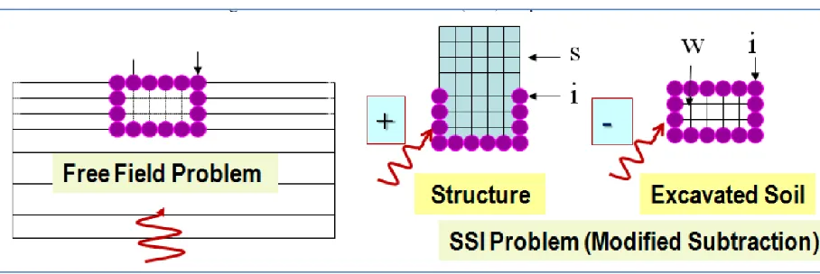
Figure 1 presents the SASSI Flexible Volume substructures of an SSI (Soil–Structure Interaction) problem. The control equation of the motion for the SSI system represented by a finite element model in frequency domain can be written as
[
𝐶𝑖𝑖𝑠− 𝐶𝑖𝑖𝑒+ 𝑋𝑖𝑖 −𝐶𝑖𝑤𝑒 + 𝑋𝑖𝑤 𝐶𝑖𝑠𝑠
−𝐶𝑤𝑖𝑒 + 𝑋
𝑤𝑖 −𝐶𝑤𝑤𝑒 + 𝑋𝑤𝑤 0
𝐶𝑠𝑖𝑠 0 𝐶
𝑠𝑠𝑠 ] { 𝑢𝑖 𝑢𝑤 𝑢𝑠} = { 𝑋𝑖𝑖𝑢𝑖′+ 𝑋𝑖𝑤𝑢𝑤′ 𝑋𝑤𝑖𝑢𝑖′+ 𝑋𝑤𝑤𝑢𝑤′ 0
} (1)
respectively. The subscripts s, i, and w denote DOF of structural nodes, nodes at interface of structure and free field soil, and nodes of excavated soil volume, respectively. Note that s DOF and w DOF should exclude DOF i in finite element implementation.
Let f represent the free field nodal DOF of w and i, which are the interaction nodes in SASSI program, the impedance matrix
𝑋𝑓𝑓 = [𝑋𝑋𝑖𝑖 𝑋𝑖𝑤
𝑤𝑖 𝑋𝑤𝑤]
Structural stiffness contribution to the global stiffness
𝐶𝑖𝑖 = [𝐶𝑖𝑖𝑠 0
0 0]
Excavated soil volume stiffness contribution to the global stiffness
𝐶𝑓𝑓 = [𝐶𝐶𝑖𝑖𝑒 𝐶𝑖𝑤𝑒
𝑤𝑖𝑒 𝐶𝑤𝑤𝑒 ]
Rewriting [𝐶𝑖𝑠 𝑠
0] = [𝐶𝑖𝑠], [𝐶𝑖𝑠
𝑒 0] = [𝐶
𝑠𝑖] and removing superscript s from 𝐶𝑠𝑠𝑠, the system
equation of motion (eq. (1)) can be rewritten as
[𝐶𝑖𝑖 – 𝐶𝑓𝑓 + 𝑋𝑓𝑓 𝐶𝑖𝑠
𝐶𝑠𝑖 𝐶𝑠𝑠 ] {
𝑢𝑓 𝑢𝑠 } = {
𝑋𝑓𝑓 𝑢𝑓′
0 } (2)
where 𝑢𝑓′ are the free field motions (displacements) at the interaction nodes. The right hand sides of equations (1) and (2) are referred to as load vector in SASSI formulation. The components of load vector has zero value for non-interaction nodal DOF and generally no-zero for interaction nodal DOF.
For the SASSI flexible volume formulation as described, all the nodes of the excavated soil volume are considered as interaction nodes; and impedance 𝑋𝑓𝑓 , free field motions 𝑢𝑓′ , and the components of the load vector have to be evaluated for those nodes. This is referred to as Direct Method (DM) to describe the SSI system and solve the system equation.
Division V
Figure 1 SASSI Flexible Volume (DM) Implementation (ref. 1)
Figure 2 Modified Subtraction Method (MSM) Implementation (ref. 1)
Formulation of SASSI Incoherent SSI Analysis
Tseng and Lilhanand (ref. 2) developed a deterministic approach to incorporate the spatial incoherence in the seismic input motions for SSI analysis using SASSI. The frequency domain ground motion coherency matrix [], constructed for the spatial locations of the nodal-points on a horizontal plane of the SASSI excavated soil volume finite element model, is first decomposed using the eigen solution of the matrix as
[Γ]𝑛 Χ 𝑛 ≅ [Φ]𝑛 𝑋 𝑚[𝜆2]
𝑚 𝑋 𝑚[Φ]𝑇𝑚 𝑋 𝑛 (3)
where n denotes number of points (stations) on the horizontal plane, and m is the number of principal coherency modes (eigen vectors) of the coherency matrix [] considered in the analysis. Matrix [Φ] contains eigenvectors of [] in column and diagonal matrix [𝜆2] contains the eigenvalues 𝜆𝑖2, i=1, 2, …, n. The two sides of equation (3) become identical when m equals n.
{𝑢𝑓_𝑖𝑛𝑐𝑜ℎ′ }
𝑛 𝑋 1= 𝜆𝑘 [𝜙𝑘]𝑛 𝑋 𝑛 {𝑢𝑓0′ } 𝑛 𝑋 1 (4)
where diagonal matrix [𝜙𝑘]𝑛 𝑋 𝑛 contains the components of k-th eigenvector (or coherency mode), 𝜙𝑘𝑖, i=1, 2, …, n.
By substituting 𝑢𝑓′ in equation (2) with 𝑢𝑓_𝑖𝑛𝑐𝑜ℎ′ as defined in equation (4), the solution to equation (2) can be obtained as the system response to coherency mode k input ground motion. Tseng and Lilhanand (ref. 2) show that structural responses (floor response spectra) obtained from combination of solution to individual coherency modes using rule of the square root of sum of the square (SRSS) are consistent with the incoherent ground motions characterized by the coherency matrix.
For an embedded structure, construction of coherency matrix and its decomposition are required for each of the horizontal layers (planes) of the excavated soil volume model if the vertical projection of the nodal points of different layers to a horizontal plane is not identical. Equation (4) evaluates the incoherent ground input motion for all the nodes at the plane, which is required for DM. For the MSM, the incoherent ground motions developed for the interaction nodes specified are required as input to equation (2).
Implementation of SASSI Incoherent SSI Analysis
An independent module that programs equations (3) and (4) and computes load vector for equation (2) of the SSI system is developed and the output of the module is used as input to ACS SASSI V3.0 (ref. 3) to perform incoherent SSI analysis of embedded structure. The steps involved in the analysis of the SSI problem are as follows:
Step 1 Perform coherent SSI analysis to obtain coherent free field nodal motions, impedance matrix and complex stiffness matrix. The map of node DOF and equation (component) number for the impedance matrix and SASSI load vector is also obtained.
Step 2 Extract SASSI excavated soil volume model information (interaction nodes, number of horizontal planes, nodal coordinates, etc.) for construction and decomposition of the coherency matrices.
Step 3 Develop incoherent load vectors for the coherency modes considered using the independent module with information obtained from steps 1 and 2.
Step 4 Perform ACS SASSI analysis using restart option with complex stiffness matrix obtained at step 1 and load vector obtained at step 3. Perform the analysis one mode at a time and repeat the analysis for all the modes considered.
Step 5 Post-process the complex transfer functions obtained at step 4 using ACS SASSI MOTION module for each of the modes analysed and combine the modal results using SRSS rule.
STUDY CASE
Soil Profile
A generic hard rock site is considered for this study. As presented in Figure 3, the soil profile has an average shear wave velocity of about 4800 ft/sec for the top 100-ft depth and the bedrock with shear wave velocity of 9200 ft/sec is reached at depth of 100 ft.
Input Control Motions and Coherency Functions
Division V
to the target ground motion response spectra are used in this study. For the SSI analysis, the location of control motions is on the ground surface level.
Figure 3 Shear Wave Velocity (Vs) and Compressional Figure 4 Input Motion Spectra Wave Velocity (Vp) Profile
Empirical plane-wave coherency functions for horizontal and vertical components of seismic ground motions for hard rock site developed by Abrahamson (ref. 4) are used for this study. Figure 5 depicts the amplitude of the coherency functions. The corresponding mathematical expressions are used to construct the coherency matrices for the nodal points on the horizontal planes of the excavated soil volume model.
SSI Model
The nuclear island structure considered in this study has a common basemat foundation to support the Auxiliary Building (AB) and Reactor Containment Building (RCB). The basemat has nominal footprint dimension of about 349 ft (North-South (NS)) x 348 ft (East-West (EW)). The foundation is embedded at depth of about 54 ft below the finished grade. The dynamic finite element structural model consists of BEAM, SHELL, SOILD and SPRING elements. Figure 6 presents overview of the structural and excavated soil volume models
(a) Structural Model (b) Excavated Soil Volume Model
Figure 6 SSI Model Overview
The SSI model has a total number of about 33000 nodes, and 9300 interaction nodes for DM and 3400 interaction nodes for MSM.
ANALYSIS AND RESULTS
Following the methodology described previously, the analyses are first performed using ACS SASSI for the coherent input motion on a total of 86 frequencies ranged from 0.1 Hz to 100 Hz for both DM and MSM. Adequacy of the frequency selected for analysis is evaluated through review of the transfer function at typical locations in the structure and it is found that for the coherent input case, the frequencies selected are adequate to capture the structural response. In-structure response spectra (ISRS) at selected typical locations of the buildings are compared for the DM and MSM to investigate the approximation of the MSM to DM. The analyses are restarted for the incoherent motion using previously generated stiffness matrix and the modified load vectors obtained from the independent module for each of the modes considered. The same set of frequencies as coherent case is computed for the incoherent case. The resulted transfer functions are reviewed to ensure the adequacy of the frequencies to capture the dynamic responses of the structure. The incoherent analyses are performed on modes 1 through 7, which are the major dominant modes and considered to be sufficient for the purpose of this study.
Division V
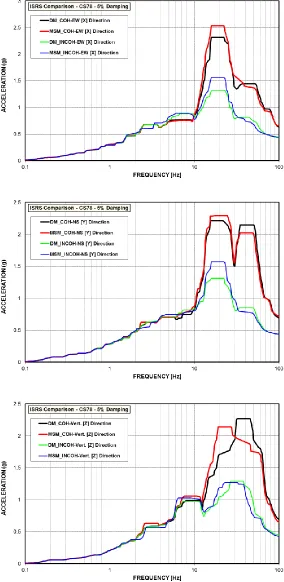
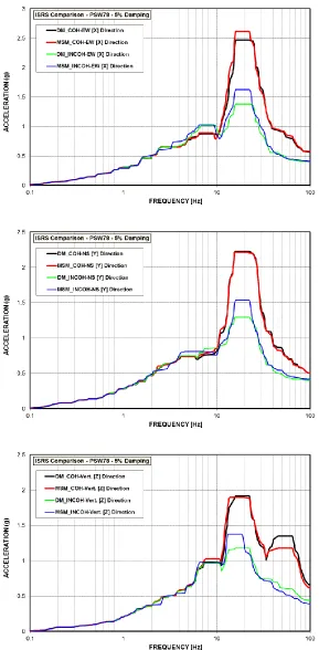
Figures 7 to 9 depict the ISRS comparisons at the abovementioned locations. The responses of horizontal directions (EW [X] and NS [Y]) and vertical direction (Vert. [Z]) are presented in the figures. The curves in the figures are denoted by the methods followed by the cases and directions. For example, curve DM_COH_EW [X] presents the EW direction response to the coherent (COH) input motion obtained from coherent SSI analysis using DM; and curve MSM_INCOH_Vert.[Z] is the vertical 7-mode-combined response to the incoherent (INCOH) motion obtained from incoherent SSI analysis using MSM.
Figures 7 to 9 indicate that for the horizontal responses to coherent ground motions, the MSM results are similar and comparable to the DM results. For the MSM vertical response, compared to DM, lower amplitude and slight shift of frequency are observed in Figures 7 and 8, respectively. The MSM excavated soil volume fundamental frequency in vertical direction is about 70 Hz. The observed lowering amplitude needs to be justified. It is noticed that for the vertical response, the degree of accuracy of MSM to DM increases with the distance of the location to the interface of structure and free field soils when comparing Figures 8 and 9 to Figure 7.
For the incoherent 7-mode-combined responses, for all three directions except AB basemat top vertical direction, the MSM results are similar and comparable to the DM results and generally the MSM peaks exceed the corresponding DM peaks. The spectral accelerations at 100 Hz from MSM and DM are consistent and this leads to conclude that significance of MSM and DM in structural design for incoherent input is minimal. For the vertical direction response at the AB basemat as shown in Figure 7, the 7-mode-combined response from DM exceed the one from MSM following the same trend as revealed from the coherent case discussed previously.
Similar trend as discussed previously for use of MSM and DM in coherent and incoherent SSI analysis is observed for other locations that are not presented in this paper.
CONCLUSION
For the large size embedded NI structure subjected to incoherent ground motions with high frequency content, compared to DM, MSM is expected to produce similar and comparable structural response in most of the locations in the structure with significantly less computing time. The degree of approximation of MSM to DM for the incoherent ground motions is similar to the case of coherent ground motions. Conclusion on applicability of MSM to coherent SSI analysis may extend to the case of incoherent analysis with justification on the responses at the locations near the interface of the structure and free filed soils.
REFERENCES
Ghiocel, M. D. and Yue, D. et al. (2013), “Validation of Modified Subtraction Method for Seismic SSI Analysis of a Large-Size Embedded Nuclear Island Model,” SMiRT-22 Transaction, 22nd International Conference on Structural Mechanics in Reactor Technology, San Francisco, California, August 2013.
Tseng, W. T. and Lilhanand, K. (1997), “Soil-Structure Interaction Analysis Incorporating Spatial Incoherence of Ground Motions,” EPRI TR-102631, Electric Power Research Institute, USA, November 1997.
Ghiocel, M. D. (2015), “An Advanced Computational Software for 3D Dynamic Analysis Including Soil-Structure Interaction,” User Manuals Revision 3, Ghiocel Predictive Technologies, Inc., March 2015.
Division V
Figure 8 Comparison of Response at Base of the Containment Structure