University of Windsor University of Windsor
Scholarship at UWindsor
Scholarship at UWindsor
Electronic Theses and Dissertations Theses, Dissertations, and Major Papers
2013
Head Gasket Finite Element Model Correlation
Head Gasket Finite Element Model Correlation
Jeff Scott Eagleson
University of Windsor
Follow this and additional works at: https://scholar.uwindsor.ca/etd
Recommended Citation Recommended Citation
Eagleson, Jeff Scott, "Head Gasket Finite Element Model Correlation" (2013). Electronic Theses and Dissertations. 4862.
https://scholar.uwindsor.ca/etd/4862
This online database contains the full-text of PhD dissertations and Masters’ theses of University of Windsor students from 1954 forward. These documents are made available for personal study and research purposes only, in accordance with the Canadian Copyright Act and the Creative Commons license—CC BY-NC-ND (Attribution, Non-Commercial, No Derivative Works). Under this license, works must always be attributed to the copyright holder (original author), cannot be used for any commercial purposes, and may not be altered. Any other use would require the permission of the copyright holder. Students may inquire about withdrawing their dissertation and/or thesis from this database. For additional inquiries, please contact the repository administrator via email
Head Gasket Finite Element Model Correlation
By
Jeffrey Scott Eagleson
A Thesis
Submitted to the Faculty of Graduate Studies
through the Department of Mechanical, Automotive and Materials Engineering
in Partial Fulfillment of the Requirements for
the Degree of Master of Applied Science
at the University of Windsor
Windsor, Ontario, Canada
2013
Head Gasket Finite Model Element Model Correlation
by
Jeffrey Scott Eagleson
APPROVED BY:
______________________________________________
Dr. R. Bowers
Department of Mechanical, Automotive and Materials Engineering
______________________________________________
Dr. D. Green
Department of Mechanical, Automotive and Materials Engineering
______________________________________________
Dr. A. Sobiesiak, Advisor
Department of Mechanical
, Automotive and Materials EngineeringDECLARATION OF ORIGINALITY
I hereby certify that I am the sole author of this thesis and that no part of this thesis has
been published or submitted for publication.
I certify that, to the best of my knowledge, my thesis does not infringe upon anyone’s
copyright nor violate any proprietary rights and that any ideas, techniques, quotations, or any other
material from the work of other people included in my thesis, published or otherwise, are fully
acknowledged in accordance with the standard referencing practices. Furthermore, to the extent
that I have included copyrighted material that surpasses the bounds of fair dealing within the
meaning of the Canada Copyright Act, I certify that I have obtained a written permission from the
copyright owner(s) to include such material(s) in my thesis and have included copies of such
copyright clearances to my appendix.
I declare that this is a true copy of my thesis, including any final revisions, as approved by
my thesis committee and the Graduate Studies office, and that this thesis has not been submitted
ABSTRACT
Finite element analysis studies are increasingly being relied upon to improve the design and
decrease overall production time of powertrain components. Multi-layer steel head gaskets are
important, passive sealing components that exist in almost all internal combustion engines and are
crucial for proper engine performance. In industry there currently exist many different approaches
for studying this component using finite element analysis.
This study attempted to give insight into what finite element methods are currently being used by
analysts and if their results correlate with physical test results. The category of finite elements
studied for use in the gasket assembly were dependent on the type of results required and included
conventional shell, continuum shell, gasket type and three-dimensional solid elements. By use of
ABAQUS software and Fuji Pressure Film comparisons, it was found that each element type has
strengths and limitations regarding real world correlation, computational expense and ease of
DEDICATION
ACKNOWLEDGMENTS
I would like to thank the following people, whom I could not have completed the project without:
Dr. Peter Frise and Ms. Jan Stewart from Auto 21 and the University of Windsor for the fantastic organizational job they have done with the entire Masters program.
Dr. Sobiesiak for his hard work, patience and information provided on powertrain components.
Mr. Mohammed Malik for his continued support throughout the entire two year program.
Mr. Patrick Baer for his patience, guidance and genuine interest in the entire project.
Mr. Paul Gardiner for his continued help with the project.
Mr. Raffaele Bonavolonta and the CRF team for their hospitality, hard work and support during my time in Torino.
Mr. Adrian Trifan for his constant support and guidance while learning the ABAQUS software
Dr. Cristiana Delprete and the Politecnico di Torino staff for their support throughout the project
TABLE OF CONTENTS
DECLARATION OF ORIGINALITY ... iii
ABSTRACT...iv
DEDICATION ...v
ACKNOWLEDGMENTS ...vi
LIST OF TABLES ...xi
LIST OF FIGURES ... xii
LIST OF ABBREVIATIONS/SYMBOLS ...xvi
NOMENCLATURE ... xvii
Chapter 1: Introduction ...1
Chapter 2: Literature Review ...4
2.1 Head Gasket Basics ... 4
2.2 Head Gasket Design ... 4
2.3 Gasket Failure Modes ... 7
2.4 Non-linearity in Gaskets ... 9
2.5 Gasket Analysis Using Finite Element Methods ... 9
2.5.1 Axisymmetric Methods ... 10
2.5.2 Proteus® Software ... 11
2.5.3 The Victor Reinz Approach ... 12
2.6 Finite Element Theory ... 18
2.6.1 Gasket Elements ... 21
2.6.2 Shell Element Theory ... 25
2.6.3 Axisymmetric Shell Element Theory ... 26
2.7 Fuji Pressure Sensing Film... 26
Chapter 4: Methodology ...29
4.1 Ideal Gas Law Calculations ... 29
4.2 Gasket Layout ... 31
4.3 Series 1: Axisymmetric Gasket Analysis ... 31
4.3.1 Axisymmetric Procedure ... 32
4.3.2 Axisymmetric Interactions and Constraints ... 34
4.3.3 Axisymmetric Mesh and Materials ... 35
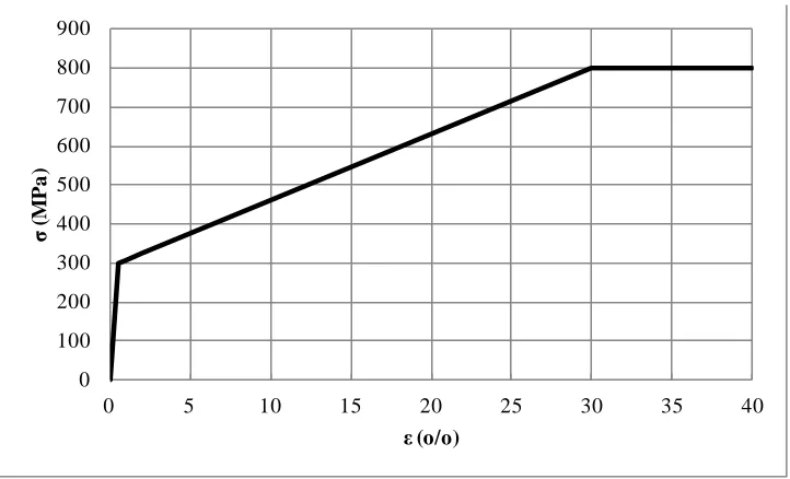
4.3.4 Axisymmetric Loading Conditions ... 36
4.3.5 Convergence and Contact Controls ... 37
4.4 Series 2: Single Cylinder Model with Varying Gasket Representation... 38
4.4.1 Procedure and Mesh ... 38
4.4.2 Single Cylinder Materials ... 41
4.4.3 Single Cylinder Steps ... 43
4.4.4 Single Cylinder Constraints ... 43
4.4.5 Single Cylinder Loading Conditions ... 43
4.4.6 Single Cylinder Boundary Conditions ... 44
4.4.7 Single Cylinder Field Output Requests ... 44
4.4.8 Single Cylinder Interactions and Properties ... 44
4.4.8.1 Sliding Formulation (Tracking Approach) ... 45
4.4.8.2 Contact Discretization Method ... 45
4.4.8.3 Slave Adjustment ... 46
4.4.8.4 Friction Formulation... 46
4.4.8.5 Pressure Overclosure ... 47
4.4.8.6 Separation... 47
4.4.8.7 Non-Linear Geometry Option... 47
4.4.8.8 Gasket Thickness Normal Directions ... 48
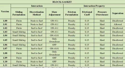
4.4.9 Interactions and Properties Used ... 48
4.4.10 Single Cylinder with Mesh Refinement... 50
4.4.11 Gasket Model using Conventional Shell, Continuum Shell and 3D Elements ... 52
4.4.12 Varying Gasket Element Type Procedure ... 53
4.5 Series 3: Full Bank Analysis at Varying Engine Operating Conditions ... 55
4.5.2 Full Bank Mesh ... 55
4.5.3 Full Bank Steps... 57
4.5.4 Full Bank Constraints ... 58
4.5.5 Full Bank Loads... 58
4.5.6 Varying Bolt Loads ... 59
4.5.7 Peak Pressure Addition... 60
4.5.8 Full Bank Boundary Conditions ... 61
4.5.9 Full Bank Output Requests ... 61
4.5.10 Full Bank Interactions ... 62
4.5.11 Application of Thermal Map ... 62
Chapter 5: Results and Discussion...65
5.1 Series 1: Axisymmetric Results ... 65
5.1.1 Axisymmetric Stresses and Strains ... 65
5.1.2 Axisymmetric Fuji Pressure Film Comparison ... 66
5.1.3 Axisymmetric Bead Stiffness ... 67
5.1.4 Axisymmetric Discussion ... 68
5.2 Series 2: Single Cylinder Results ... 70
5.2.1 Areas of Incompatibility ... 76
5.2.2 ABAQUS Interactions and Settings Discussion ... 77
5.2.3 Single Cylinder Mesh Refinement Results ... 78
5.2.4 Mesh Refinement Discussion ... 82
5.2.5 Varying Gasket Element Types ... 83
5.2.6 Varying Gasket Element Discussion ... 84
5.3 Series 3: Full Bank Results ... 85
5.3.1 Fuji Pressure Film Comparison ... 86
5.3.2 Contact Pressure on Deck Faces ... 90
5.3.3 Cold Firing Normal Pressure Comparison ... 91
5.3.4 Head and Head Gasket Deformation... 92
5.3.5 Boundary Conditions with Thermal Map ... 94
5.3.6 Reduced Bolt Loading for All Studs ... 95
5.3.7 Varying Bolt Loading for the 180° Studs ... 97
5.3.9 Reduction in Normal Pressure from Cold Clamping to Hot Firing and from Hot
Clamping to Hot Firing Conditions ... 101
5.3.10 Gasket Normal Stresses For the Cold Clamping, Hot Clamping and Hot Firing Conditions ... 104
5.3.11 Gasket Membrane Shear stresses ... 106
5.3.12 Full Bank Discussion... 107
5.4 Root Cause of Gasket Failure ... 107
5.5 Fuji Pressure Film Resolution ... 109
5.6 Contact Pressure Verification ... 109
5.7 Future Studies ... 110
Chapter 6: Conclusions ...112
REFERENCES/BIBLIOGRAPHY...114
APPENDICES ...117
Appendix A: Technique for Angular Analysis ...117
Appendix B: Engine Data ...123
Appendix C: Cold Clamping S11 Pressures for All Cylinders ...127
LIST OF TABLES
Table 1: Engine Data ... 29
Table 2: Ideal Gas Law Results ... 30
Table 3: Interactions and Constraints used in the Axisymmetric analysis ... 35
Table 4: Material information used for the axisymmetric analysis ... 35
Table 5: Mesh Information Summary for the Quarter Bank Analyses ... 41
Table 6: Material Properties used in the Single Cylinder Model ... 42
Table 7: at the Block-Gasket interface for Series 2 ... 49
Table 8: Interactions at the Head-Gasket interface for Series 2... 49
Table 9: Interactions at the Stud Interfaces for Series 1 ... 50
Table 10: Mesh Refinement increases for Nodes and Elements. ... 52
Table 11: Right Bank Element Totals ... 57
Table 12: Steps used for Series 3 ... 58
Table 13: Reduced Bolt Forces ... 59
Table 14: Summary of Series 1 Results ... 72
Table 15: Mesh Refinement Results ... 79
Table 16: Contact Pressure Calculation ... 110
LIST OF FIGURES
Figure 1: Exploded view of the gasket CAD ... 1
Figure 2: Full Bead (left) and Half Bead (right) of gasket layers ... 5
Figure 3: 1D spring stiffness diagrams of engine assembly (left) and gasket assembly (right) ... 6
Figure 4: Types of bead profiles in gasket layers; Series (left) and Parallel (right) ... 6
Figure 5: Pressure vs Closure curves used by ABAQUS; nonlinear elastic model with damage (left) and nonlinear elastic-plastic model (right) ... 9
Figure 6: Victor Reinz CAE Approach [Popielas et al., 2003 (0483)] ... 13
Figure 7: Victor Reinz CAE Approach - Part A [Popielas et al., 2003 (0483)] ... 15
Figure 8: Victor Reinz CAE Approach - Part B [Popielas et al., 2003 (0483)] ... 16
Figure 9: ABAQUS representation of Specialized Gasket Elements ... 23
Figure 10: Gasket Element showing three uncoupled behaviours ... 24
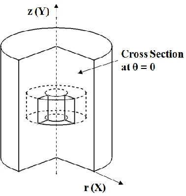
Figure 11: Representation of Axisymmetric Element... 26
Figure 12: Top view and layout of the gasket to be used throughout report ... 31
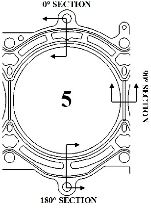
Figure 13: Sections used for the Axisymmetric analysis ... 32
Figure 14: Surfaces of cross sections in Catia ... 33
Figure 15: Axisymmetric Assembly of 90° Section in ABAQUS ... 34
Figure 16: Axisymmetric Assembly of 0° Section (top) and 180° Section in ABAQUS ... 34
Figure 17: True stress-true strain data used for the analysis... 36
Figure 18: Partition Regions of single cylinder assembly ... 40
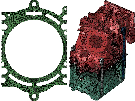
Figure 19: Mesh of the gasket (left) and mesh of the Quarter Bank Model (right). ... 41
Figure 20: Location of Bead profiles in gasket composed of Gasket Elements ... 42
Figure 21: Loading/Unloading curves of Gasket Sections. Note the high stiffness curve of the BODY + STOP which continues above the chart ... 42
Figure 22: Stud Labels, Interactions, Constraints and Loading conditions. The bolt load tensions are shown by the green arrows. ... 43
Figure 23: From left to right, on the block deck face, the meshes of 3.01, 3.02, 3.03 and 3.05. The hexagonal elements can be seen in Analysis 3.05. ... 52
Figure 24: Surface model of the gasket assembly (Left) and meshed shells of gasket assembly (right) ... 54
Figure 25: Mesh Regions of the Head (left) and Block (right) ... 56
Figure 26: The regions of the head with larger elements ... 56
Figure 27: The entire meshed Right Bank Engine Assembly ... 57
Figure 29: Bolt loading conditions for full bank. Full engine view (left) and end view with engine
hidden (right) ... 59
Figure 30: Locations of altered bolt loads ... 60
Figure 31: Locations of cylinder pressure (red surfaces) ... 60
Figure 32: Symmetric boundary locations (left) and Encastre boundary conditions (right) ... 61
Figure 33: Temperature map of block in °C. ... 64
Figure 34: Axisymmetric VM (top), vertical pressure (middle) and shear stresses (bottom) for 0° Section... 65
Figure 35: Axisymmetric VM (left), vertical pressure (middle) and shear stresses (right) for 90° Section... 65
Figure 36: Axisymmetric VM (top), vertical pressure (middle) and shear stresses (bottom) for 180° Section... 66
Figure 37: Comparison of 0° Section (top) with Fuji Film (bottom)... 67
Figure 38: Comparison of 90° Section (top) with Fuji Film (bottom) ... 67
Figure 39: Comparison of 180° Section (top) with Fuji Film (bottom) ... 67
Figure 40: Force vs Closure curves for all Axisymmetric Sections ... 68
Figure 41: S11 pressure (left) and E11 Gasket Closure (right) ... 73
Figure 42: Areas of Von Mises Spiking (left) and E11Gasket Closure spotting (right) with a scale factor of 5 ... 74
Figure 43: Typical results of Series 2 showing no Spiking and Spotting, as seen in Series 1... 74
Figure 44: Circumferential S11 Pressures on all of the Series 1 Stops... 75
Figure 45: Circumferential S11 Pressures on all of the Series 1 Flexstops ... 75
Figure 46: Circumferential S11 Pressures on all of the Series 1 Full Beads ... 76
Figure 47: Areas of incompatibility at varying element types ... 76
Figure 48: Circumferential S11 Pressures on all of the Mesh Refinement Study STOP bead ... 80
Figure 49: Circumferential S11 Pressures on all of the Mesh Refinement Study FLE XSTOP... 80
Figure 50: Circumferential S11 Pressures on all of the Mesh Refinement Study FULLBEAD... 81
Figure 51: Pressure Distributions at the Engine Block deck faces of Mesh Refinement Study. .... 82
Figure 52: Von Mises stress at each gasket layer and Fire Ring. Clockwise from Top Left; Layer 1, Layer 2, Layer 3, Fire Ring, Layer 4... 83
Figure 53: Contact pressure on head face and pressure at gasket layer 1 compared to the Fuji Film results (right) ... 84
Figure 55: FEA Analysis of the Right Bank Gasket elements (Top) and High Fuji Paper results as
supplied by Dodge (Bottom)... 87
Figure 56: FEA Result (left) and Fuji Paper Result (right) of Cylinder 7... 88
Figure 57: FEA Result (left) and Fuji Paper Result (right) of Cylinder 5... 89
Figure 58: Contact Pressure on Cylinder 5 and 7 Deck Faces ... 90
Figure 59: S11 Pressure values at Cylinder 1for Cold Clamping and Cold Firing ... 91
Figure 60: S11 Pressure values at Cylinder 3 for Cold Clamping and Cold Firing ... 91
Figure 61: S11 Pressure values at Cylinder 5 for Cold Clamping and Cold Firing ... 92
Figure 62: S11 Pressure values at Cylinder 7 for Cold Clamping and Cold Firing ... 92
Figure 63: Areas of cupping on the Head deck surface ... 93
Figure 64: Gasket closure for Cold Clamping (left) and hot Clamping (right) ... 93
Figure 65: Head Deformation for Cold Clamping (left) and hot Clamping (right) at 100X, No Section... 94
Figure 66: Deformation for Cold Clamping (left) and hot Clamping (right) at 100X, Section cut at Medium Length Studs ... 94
Figure 67: Deformation for Cold Clamping (left) and hot Clamping (right) at 100X, Section cut at Cylinder Centre ... 94
Figure 68: Deformation for Cold Clamping (left) and hot Clamping (right) at 100X, Section cut at Long Length Studs... 94
Figure 69: Von Mises Stress values after application of Thermal map. Original BCs (left) and improved BCs (right) ... 95
Figure 70: Temperature Map addition on Engine Assembly... 95
Figure 71: S11 Pressures during reduced Bolt Loads, Cylinder 1 ... 96
Figure 72: S11 Pressures during reduced Bolt Loads, Cylinder 5 ... 96
Figure 73: E11 Gasket Closure of the STOP of Cylinder 5, varying stud loads at the 180° studs 97 Figure 74: E11 Gasket Closure of the FLEXSTOP of Cylinder 5, varying stud loads at the 180° studs ... 98
Figure 75: E11 Gasket Closure of the FULLBEAD of Cyl 5, varying stud loads at the 180° stud 98 Figure 76: S11 Gasket Pressure of the STOP of Cylinder 5, varying stud loads at the 180° stud .. 98
Figure 77: S11 Gasket Pressure of the FLEXSTOP of Cyl 5, varying stud loads at the 180° studs99 Figure 78: S11 Gasket Pressure of the FULLBEAD of Cyl 5, varying stud loads at the 180° studs ... 99
Figure 80: E11 Gasket Closure values at Cylinder 3 for Cold Clamping, Hot Clamping and Hot
Firing... 100
Figure 81: E11 Gasket Closure values at Cylinder 5 for Cold Clamping, Hot Clamping and Hot Firing... 100
Figure 82: E11 Gasket Closure values at Cylinder 7 for Cold Clamping, Hot Clamping and Hot Firing... 101
Figure 83: S11 Pressure % change from Cold Clamping to Hot Firing for Cylinder 1. Note that STOP values are not shown. ... 101
Figure 84: S11 Pressure % change from Hot Clamping to Hot Firing for Cylinder 1... 102
Figure 85: S11 Pressure % change from Cold Clamping to Hot Firing for Cylinder 3. Note that STOP values are not shown. ... 102
Figure 86: S11 Pressure % change from Hot Clamping to Hot Firing for Cylinder 3... 102
Figure 87: S11 Pressure % change from Cold Clamping to Hot Firing for Cylinder 5. Note that STOP values are not shown. ... 103
Figure 88: S11 Pressure % change from Hot Clamping to Hot Firing for Cylinder 5... 103
Figure 89: S11 Pressure % change from Cold Clamping to Hot Firing for Cylinder 7. Note that STOP values are not shown. ... 103
Figure 90: S11 Pressure % change from Hot Clamping to Hot Firing for Cylinder 7... 104
Figure 91: S11 Pressure values at Cylinder 1 for all Conditions ... 104
Figure 92: S11 Pressure values at Cylinder 3 for all Conditions ... 105
Figure 93: S11 Pressure values at Cylinder 5 for all Conditions ... 105
Figure 94: S11 Pressure values at Cylinder 7 for all Conditions ... 105
Figure 95: S23 Membrane Shear Stress for Cyl 1, Cold Clamping, Hot Clamping and Hot Firing ... 106
Figure 96: S23 Membrane Shear Stress for Cyl 3, Cold Clamping, Hot Clamping and Hot Firing ... 106
Figure 97: S23 Membrane Shear Stress for Cyl 5, Cold Clamping, Hot Clamping and Hot Firing ... 107
LIST OF ABBREVIATIONS/SYMBOLS
1D One Dimensional
2D Two Dimensional
3D Three Dimensional AFR Air-Fuel Ratio BC Boundary Condition CAD Computer aided design CAE Computer aided engineering
CC Cold Clamping
CF Cold Firing
CPU Central processing unit CTC Chrysler Technical Center FE Finite Element
FEA Finite Element Analysis FEM Finite Element Method
FIAT Fabbrica Italiana Automobili Torino GPa Gigapascal
GVRA General Victor Reinz Approach
HC Hot Clamping
HCV Higher Calorific Value HF Hot Firing
ISO International Organization for Standardization mm Millimeter
MLS Multi Layer Steel
MPa Megapascal
N Newton
NLGEOM Non-Linear Geometry Option OEM Original Equipment Manufacturers PCP Peak Combustion Pressure
PdT Politecnico di Torino RAM Random access memory RPM Revolutions per Minute SDI Severe Discontinuity Iteration USB Universal serial bus
NOMENCLATURE
X Angle of Bead Y Height of Bead V Width of Full Bead ks Stiffness of Studs
kH Stiffness of Head
kB Stiffness of Block
kL Stiffness of Engine Liner
kG Stiffness of Entire Gasket
k1 Stiffness of Gasket Layer 1
k2 Stiffness of Gasket Layer 2
k3 Stiffness of Gasket Layer 3
k4 Stiffness of Gasket Layer 4
εx Strain in x-Direction
u Displacement
σx Stress in x-Direction E Modulus of Elasticity {F} Global nodal Force vector [K] Structure global stiffness matrix {d} Vector of displacements
ISc Maximum amount of severe discontinuity iterations
PMOD Modified Cylinder Pressure PMAX Maximum Cylinder Pressure RC Cylinder Radius
RI Intake Valve Radius RE Exhaust Valve Radius S Stresses (Gasket) E Strains (Gasket)
S11 Pressure in the gasket element S22 Direct membrane stress. S33 Direct membrane stress S12 Transverse shear stress S13 Transverse shear stress S23 Membrane shear stress E11 Gasket closure
ηOTTO Efficiency of the Otto Cycle
ρ Density
mAIR (kg) Mass
rv Compression Ratio of Engine
k Ratio of Specific heat capacities Pn Pressure at step n of Otto Cycle vn Volume at step n of Otto Cycle vr Relative specific volume of air qn Heat transfer per unit mass un Specific Internal Energy
cv Constant Volume Specific Heat
cp Constant Pressure Specific Heat r Axisymmetric Radial Coordinate z Axisymmetric Height Coordinate
Chapter 1: Introduction
The head gasket is the most important passive sealing element in the internal combustion engine.
It is positioned between the cylinder head and block and its purpose is to provide a gas tight seal
between the cylinder(s), the water jackets, oil passages and the ambient air, liquids and gases. The
area of the gasket around the cylinder must be robust enough to withstand the same pressures that
are exerted on the pistons while ensuring that there is no leakage of coolant or combustion gases
among the three volumes. It must be able to accomplish this at all engine temperatures and
pressures without malfunction, as a failure of the engine gasket usually results in a failure of the
full engine.
The current Dodge NASCAR engine uses a multi-layer steel (MLS) construction that consists of
four layers of stainless steel sheets that are pressed firmly together by the compressive forces of
the cylinder head bolts. Between layers 2 and 3 exists a stainless steel fire ring. The exploded
view of the gasket is shown in Figure 1. Also, previous versions of the gasket have used a thin
rubber coating which helps with sealing between each of the steel components. One of the major
concerns is the lack of an accurate head gasket model for use during Finite Element Analysis
(FEA). Preliminary testing has shown that the current digital model does not accurately represent
what is occurring in the real life situation, where failures have occurred during testing. The
failures are usually cracking of the gasket at the cylinders 5 and 7 exhaust locations.
Figure 1: Exploded view of the gasket CAD
Finite Element Analysis is a powerful tool used by engineers and designers to determine how a
part or assembly behaves when subjected to various boundary conditions. Some of the parameters
element method is a numerical technique, ideally suited to digital computers, in which a
continuous elastic structure (continuum) is divided (discretized) into small but finite well-defined
substructures (elements) [Hibbit, et al, 2001]. Using matrices, the continuous elastic behaviour of
each element is categorized in terms of the element’s material and geometric properties, the
distribution of loading (static, dynamic and thermal) within the element, and loads and
displacements at the nodes of the element. The element’s nodes are the fundamental governing
entities of the element, as it is the node where the element connects to other elements, where
elastic properties of the element are established, where boundary conditions are assigned, and
where forces (contact or body) are ultimately applied [Budynas, 1999]. One of the more powerful
software packages available and the one that will be used for the project is ABAQUS Standard.
ABAQUS is a suite of engineering simulation programs, based on the finite element method that
can solve problems ranging from relatively simple linear analysis to the most challenging
nonlinear simulations. The software contains an extensive library of elements that can model any
geometry. It has an equally extensive list of material models that can simulate the behaviour of
most typical engineering materials including metals, rubber, polymers, composites, reinforced
concrete, crushable and resilient foams, and geotechnical materials such as soils and rock [Hibbit,
et al, 2001].
Head gasket designs are relatively complex and thus usually left to the gasket suppliers to design,
engineer and test. When the head and block of the engine are designed by the engine development
team, the contact interface is given to the gasket supplier to use for their design. The gasket
supplier creates the gasket based on the information, but does not analyze their part using proper
engine CAD components. Essentially, the most important seal of an engine is being designed by
two separate teams with gaps of information between each other. If there is an issue with the
surface contact joint of the engine, this situation is difficult to resolve due to the information gap.
If a database of knowledge is built within the Chrysler, FIAT and Dodge Motorsports Team,
future head gasket issues can be solved from within the company, without relying on potentially
expensive outside support. The knowledge can also be used to create improved designs of engine
heads and blocks.
In order to speed up the development time of engine design, it is necessary to use computational
analysis as much as possible. The current finite element analysis methods used by Chrysler, FIAT
and Dodge Motorsports are reliant on a provided single layer gasket model for analysis. This
simplified gasket model makes many assumptions regarding stresses, strains and deflections on
investigating past, present and future FE techniques used in industry to analyze MLS head gasket
behaviour and to determine a root cause of the current gasket failure. The results found can then
be correlated to physical test data found by using Fuji Pressure Film on the real-world engine
assembly. The major objective is to determine the strengths and weaknesses of FE techniques to
improve company knowledge that will help analysts more accurately represent the physical head
gasket during future studies. Head gaskets are fairly complex parts, so a thorough procedure for
virtual simulation must be completed. Much of the physical testing is to be completed in
partnership with the Penske Racing Team. Various analyses must be completed using ABAQUS
FEA software to give a complete range of results. When complete, there will be a database of new
knowledge regarding head gasket FEA that can be referenced by all Chrysler and FIATs designers
in the future.
Although specifically dealing with NASCAR head gaskets, the completed research on head
gaskets and FEA methods will decrease design time and improve engine durability for all
Chapter 2: Literature Review
The literature review was conducted using SAE papers, books and The ABAQUS user's manual.
Much of the topics discussed in the thesis are based on proprietary information in industry, so
only basic information was able to be found using these sources. Detailed procedures and
techniques were difficult to obta in without having direct access to proprietary industrial reports.
2.1 Head Gasket Basics
The head gasket is the sealing element between the cylinder block and the head. The active
sealing components of an engine are the intake/exhaust valves and the piston rings, which are
constantly in cyclic motion [Stone, 1985]. Although it's role is passive, a head gasket's function is
extremely important for proper engine function. The gasket must withstand the high pressures and
temperatures of the combustion process and ensure that the combustion gases, coolant and oil
passages remain sealed from one another. This function must occur at varying engine speeds and
loads, at which the entire assembly is at varying stages of stress and temperature. Multi-layer steel
head gaskets are currently the favorable choice for the internal combustion engine and are a
growing technology in the heavy duty diesel industry. There are many reasons for the popularity,
such as improved reliability, increased sealing with minimal stud forces, better chemical and
thermal resistance, higher control of clamped gasket thickness, decreased bolt force fluctuations,
improved levels of dynamic response and enhanced emission control [Chen, 2002].
2.2 Head Gasket Design
The MLS cylinder head gasket is composed of several layers of steel, which form the body of the
gasket. The body material is usually composed of low stiffness steel whose function is to simply
provide support to the gasket. Other materials that are commonly used are graphite and
composites [Hebert, et al, 1998]. Within the layers, there of a number of distinct areas, all of
which play an important role in the sealing process. Beads of a gasket are formed into the active
layers of the gasket, which are the top and bottom sheets. The beads are responsible for proper
sealing and convert bolt forces into sealing forces. The bead material located around the cylinder
bore is known as the stopper area. This area is the first sealing line against leakage and must be
the thickest and stiffest in order to provide proper sealing pressure against the combustion gases.
The stopper (or fire ring) is usually a different, stiffer, material than the rest of the gasket. There
are many forms of stopper areas and even gaskets that do not use a stopper. It has been found that
the stopper area takes approximately 60-80% of the stress due to the bolt loading [Popielas, et al,
2003 (0484)]. Due to this, the stopper area has a major influence on the load distribution, head lift
the full beads and the active layers of the gasket. It has a significant effect on the fatigue life of
the gasket. The second sealing line is directly behind the stopper area and is composed of formed
beads in the active layers. Beyond these layers lie the active layers of the body area, which
provide sealing for the oil and coolant circuits, as well as sealing from the ambient environment.
Commonly, there is coating on the gasket layers. Sometimes, there is only a coating on the top
and bottom surface of the gasket at the deck interface. The coating acts as another barrier against
gas and fluid leakage as well as altering the shear behaviour of the interfaces [Popielas, et al,
2000].
There are two types of beads used in a MLS gasket; the full bead and the half bead. Beyond
having two different geometries, as shown in Figure 2, the beads perform different functions. The
specific geometry of the beads are formed by lengths Y and V, and by angle X [Catalogue Cylinder Head Gaskets…, 2013]. During the installation of the head gasket, the full beads are
compressed until they reach the height of the stopper, or until the bead resistance equals the bolt
clamping force. The sealing force created by the full bead is relatively high, which is required to
properly seal the combustion chambers. The main purpose of a full bead is to equalize the
dynamic sealing gap oscillations between the cylinder head and cylinder block at high combustion
pressures. The half bead's function is mainly to seal against coolant and oil in the areas far away
from the cylinder, at bolt holes and at the outer surfaces. Since the half beads have a lower sealing
force than the full beads, the full bead is able to maintain proper sealing force at the area of most
importance, the combustion chamber. The main factors that affect the bead stiffness are geometry,
steel quality, sheet thickness and production process [Chen, et al, 2002].
Figure 2: Full Bead (left) and Half Bead (right) of gasket layers
Engine head gasket design is a complicated process as the gasket must perform many duties while
having an appropriate useful life. Therefore, it is important to balance the sealing potential versus
the overall durability of the gasket. The gasket design is driven mainly by engine geometry, but
other factors are of importance as well. These include: bolt clamping force, deck surface
compressed gasket thickness, etc [Chen, et al, 2002]. The sealing features of the gasket discussed
earlier are constructed of geometric beads or embossments. The designer uses an in-plane view at
the combustion chamber and each fluid passageway to properly design the sealing beads. The
beads of each layer are created by stamping the thin metallic layer between two halves of the tool,
which produces residual stresses in the layers. The individual layers are then stacked to attain the
desired spring stiffness characteristics and required compressed thickness between the engine
block and head. As shown in Figure 3, the gasket layer beads are basically small, single springs
with suitable stiffness, that when assembled, create a single larger spring. Spring characteristics
are determined by the layer material, thickness, hardness and geometry [Mockenhaupt, 2003]. The
layout of the beads in the adjacent layers can be classified in two ways; series or parallel [Chen, et
al, 2002]. The distinction is shown in Figure 4 and their use is dependent on the dynamics of the
bolted joint, cyclic loading caused by the combustion process and thermal distortion of the engine
assembly. In the gasket industry, there are many arrangements of the beads, therefore it is a
challenge for the designer to meet the static and dynamics requirements of engine assembly. The
entire gasket must provide adequate sealing at maximum, minimum and alternating loads while
resisting fatigue effects over the entire gasket life. Any degradation of sealing ability will result in
decreased engine performance and even failure. The preceding reasons demonstrate the need for
analytical methods in the design phase of a MLS gasket. The goal of the gasket designer is to
optimize the gasket contact stresses and minimize the dynamic motion of the head [Chen, et al,
2002].
Figure 3: 1D spring stiffness diagrams of engine assembly (left) and gasket assembly (right)
2.3 Gasket Failure Modes
Metallic composition and feature geometry of the head gasket are important parameters to
consider during design. As with any metallic element that is subjected to cyclic loads, head
gaskets have fatigue limits that must be taken into account during the design process. The
dimensions and forming parameters of the full bead of the gasket resulted in changes in gasket
durability. Study results show that the selection of embossing parameters producing less
deformation of the bead plate is beneficial for the improvement of durability while the flattening
has marginal influence. The fatigue durability is improved with the increase of in the width of the
full-bead and the radial length of the bore-side flat region [Cho, et al, 2005].
Gasket layers are usually composed of hardened stainless steel. In an annealed state, stainless
steel mostly consists of austenitic material. In order to get the proper spring properties from the
material it must be hardened, which can be achieved by cold rolling. This cold rolling process
introduces a martensite phase into the material. The result is a smaller grain size, altered grain
structure, decreased elongation, and increased mechanical properties. When the beads are stamped
into the metal sheets, additional cold working is performed and the hardness and mechanical
properties at these areas is increased due to the plastic deformation. This occurs on only o ne side
of the metal sheet. On the other side there exists decreased elongation which increases the
probability that the bead will fatigue crack with the addition of tensile stress. Under engine
assembly, tensile stress is induced as the bead is compressed [Kestly, et al, 2000].
As the martensite is formed from cold working, defects are created in the structure. Under the
repeated cyclic loading of an ICE, the stress levels change and the defects begin to increase.
When a sufficient amount of defects are created, the part will crack, most likely at its weakest
area. The weakest area is where there exists tensile stresses, high stress levels, and highest
fluctuating stress levels.
Brinelling is defined as a contact stress that permanently deforms the surface to which it is
applied. The material can flow due to the deformation under pressure. It can result in damage of
the cylinder block or head deck faces and also the gasket itself. It is most likely to occur in engine
components made from aluminum alloys. Fretting occurs locally on a surface and is defined as
pockets, drag marks and stripes in the material. When friction is high enough between two
surfaces, aluminum particles can be cold welded to the metallic gasket surface. Fretting can only
occur if there is gasket movement tangent to the deck surface in addition to the usual vertical
will not occur without fretting. One theory suggests that the scratches due to fretting are a starting
point for fatigue cracking due to the stress concentrations at these areas. Also there is a theory that
the scratches generate the higher friction forces and added deformation in the material which
results in changes in the structure [Kestly, et al, 2000].
The two most common failure modes of a MLS gasket are excessive leakage and fatigue cracking.
[Chen, 2002] Large head lift during the dynamic motion of the cylinder head is the main
contributor to fatigue failure due to increased amplitudes of cyclic stresses. The two major factors
that cause head lift are thermal loading and firing pressure. Small cracks that exist in the gasket
layers grow slightly every cycle and eventually open to a size that causes bead failure.
The forming process of the beads in each layer is achieved by stamping the thin metallic sheets
between two dies [Popielas, et al, 2000]. The process shapes the bead by deforming the material
beyond its yield stress. Due to the compressive and tensile forces present, there will always exist
residual stresses in the gasket layer. These stresses should not be ignored when doing a full
analysis on the gasket assembly.
A major consideration of gasket sealing are the stresses created in the engine head due to its
bending over the stiff gasket beads, which can lead to fatigue failure under high cylinder firing
cyclic loads. The stiffness of the gasket also influences the distorted shape of the cylinder bore
under cold and hot assembly conditions, which can lead to piston ring conformability problems,
excessive oil consumption, and unacceptable emissions levels [Hebert, et al, 1998].
The efficiency of the head gasket sealing depends on the pre-stressing force of the hold-down
bolts, without taking into consideration any thermal stresses resulting from the temperature
distribution within the cylinder head. It was also found that the location of maximum contact
pressure on the gasket is increased when the thermal loading is included in the analysis [Popielas,
et al, 2003 (0483)]. It was found that the capacity of the gasket sealing mainly depends upon the
pre-stressing of the bolts, which are also the source of maximum external loading on the inner
structure of the cylinder head. When thermal loading is incorporated into the analysis, the location
of the weakest contact pressure on the raised portion of the gasket is changed due to the effect of
thermal stress/strain. The analytical results show that the thermal stresses provide a positive
support for the efficiency of gasket sealing. Under operating conditions with gas pressure,
however, there exists an opposite force to the direction of the pre-tensioned bolts, which increases
the possibility of gas leakage. The solution is to increase the magnitude of the assembly force
this early in the gasket design process, the gasket structure can be improved in the areas of worst
sealing.
2.4 Non-linearity in Gaskets
Since cylinder head gaskets are made of multiple layers spaced apart from one another, the
structure possesses material properties which are directionally dependent (anisotropic) and
non-linear [Hebert, et al, 1998]. When compressed, the multiple layers are bent beyond their yield
stress and undergo plastic deformation. The multiple gasket layers come into contact with each
other, which results in an increasing slope of the stress-strain curve. Due hysteresis in the gasket
assembly, as the load is decreased, it does not follow the same loading curve that it originally
followed. For example, the curve on the left in Figure 5 shows that the loading curve will follow
AB as the gasket is compressed. If the gasket is unloaded, it will follow the unloading curve BCA.
ABAQUS software deals with the nonlinearities by two different methods; nonlinear elastic
model with damage and nonlinear elastic-plastic models. The two different types of gasket curves
are shown in Figure 5 below [Hibbit, et al, 2010].
Figure 5: Pressure vs Closure curves used by ABAQUS; nonlinear elastic model with damage
(left) and nonlinear elastic-plastic model (right)
2.5 Gasket Analysis Using Finite Element Methods
In order to reduce the time and costs of the engine development cycle, Computer Aided
Engineering (CAE) is an important tool for gasket design. For the commercial automobile market,
turnaround for engine model generation has been greatly reduced from the past [Kestly, et al,
2000]. As a result, the short development time means that it is very difficult to get real
information through testing and experimentation. This means that CAE must be used to make the
MLS gasket design meets the fit, form and function requirements of the application; thus the solid
models of the engine block, head and studs must be included in the FE analysis, along with the
environmental parameters and installation information. The costs and time associated with
implementing MLS head gaskets are encouraging increased levels of technical knowledge early in
the design process. The design process generally relies heavily on advanced experimental,
analytical and numerical methods. It is very important to use the Finite Element method of the full
engine assembly, including the gasket, in order to aid in the understanding of motion levels and
deflections of the MLS gasket sealing features, well before production [Popielas et al, 2003
(0481)]. The pre-production analyses help the designer to understand the capability of the design
to meet sealing and durability requirements of the gasket while allowing it to be brought into
production faster. The numerical simulation modeling allows the engineer to review multiple
loading and operating conditions, which increase the probability of an initial design being
successful.
2.5.1 Axisymmetric Methods
In the past, traditional approaches to gasket analysis lacked information of the head and block due
to customer confidentiality, and therefore used only 2D axisymmetric models and oversimplified
assumptions (permanently rigid mating surfaces, room temperature working temperatures, etc).
Interactions at the deck faces were usually ignored. MLS gaskets are subjected to high
compressive stresses during loading and the compressive responses are non-linear. Complexities
in the geometry and material behaviour make detailed modeling of gaskets using continuum
elements extremely time consuming for internal stress analysis. Therefore, two-dimensional
axisymmetric analysis was the only approach to the complicated problem. This type of analysis
not only provides a solution to the longer running time for the three-dimensional models, but also
provides a large amount of information on the behaviour and interaction between the engine
hardware, and also within the different layers of the gaskets. Typically, a 2D axisymmetric
multi-layer model consists of the different multi-layers of the gasket geometry, the rubber coating on the
metal, and the residual stresses due to the forming process. The steps involved are as follows
[Popielas, et al. 2003 (0483)]:
1. The results file from a specialty software is outputted. The single layer forming process
calculation is then converted into an input file for multi-layer analysis using specialized
sub-routines.
3. The Input file for Multi-layer 2D axis-symmetric model is created for different load
cases depending on engine operating parameters. Which are:
Step 1: Apply the specified bolt load. Bolt load to be used for the simulation is calculated as below:
Load = [Number of bolts/Cylinder * Bolt load per bolt] * 50 % for gasoline engines
Load = [Number of bolts/Cylinder * Bolt load per bolt] * 75 % for heavy-duty engines
Step 2: Apply specified head lift off (experimental data used or the calculated lift off of a 3D calculation)
Step 3: Apply reduced bolt load
Step 4: Apply specified head lift off (Using experimental data)
The next evolution was to model the deformed surface with topography over the entire sealing
surface by using "Super Elements" [Popielas et al, 2000]. Although an improvement over the
previous methods, the deformed surface was fixed at a certain working condition and therefore
could not accurately represent transition conditions. The analyses were very limited and not
accurate enough to satisfy customer requirements. As computer hardware and FEA software
improved, MLS gaskets were able to be studied in more depth. FEA was now able to simulate the
forming process of the gasket layers and reveal the residual stress distribution with in the material.
The FEA analyst could model the male and female die shapes by using rigid elements and place
deformable material between them. Due to contact problems, these are usually left to 2D
axisymmetric models. After conversion from 2D to 3D, some commercial FEA codes will allow
the analyst to export the results with residual stress into a simplified 3D engine assembly for
further analysis. However, the prior simulation has many deficiencies such as unknown
coefficients of friction between the die and gasket layers, difficulties in modeling the rubber
gasket coating and proper simulation of the speed of the die itself [Popielas, et al, 2000].
2.5.2 Proteus® Software
In recent years, programs have been created in order to further investigate the phenomenon of
gasket residual stresses. One of the major programs is entitled Proteus®. For the 2D Analysis, the
Proteus® software is first used to determine the deformed shape of the bead layer as well as
residual stresses due to the manufacturing process. The program is also able to determine the
of cycles until cracking. Important parameters that are used by the program include: material
parameters, friction coefficient between the gasket coating and tooling, bead width and height,
tooling radius, coating thickness, etc. After these parameters are found, the information from the
Proteus® software is exported into a commercial software, such as ABAQUS or Marc. [Popielas,
et al, 2000]
2.5.3 The Victor Reinz Approach
Currently, OEMs want to determine the effects of the interaction between the gasket, engine block
and head, so the historical, less detailed methods are not appropriate. A typical procedure involves
the construction of the 3D engine block, cylinder head and conventional gasket between them.
The MLS gasket is then modeled and replaces the conventional gasket so that the differences can
be compared. This simulation would typically involve the preload of the bolts, peak firing
pressure, bolt load from stretch tests, thermal map and other variables.
One of the largest manufacturers of MLS head gasket is Victor Reinz. They have developed a
specific method for gasket analysis, known as The Victor Reinz CAE Approach and is displayed
in Figure 6 below. The first step for any analysis is to define the goal of the calculation. In gasket
analysis, there are many parameters and it does not makes sense to consider them all at the same
time. The types of parameters that need to be studied include, but are not limited to [Popielas, et
al, 2000].
Residual stress/strain distribution in the beads due to the manufacturing forming process.
Durability of the beads in the various layers
Load/deflection curves of the beads and the entire gasket assembly
Influence on corresponding components (head, block and studs)
Load distribution of the gasket at the deck faces of the assembly
Specific loads on the gasket sealing areas
Distortion of head, block, liner, studs, valve guides, valves, etc
Head lift off under peak temperature and pressure
Figure 6: Victor Reinz CAE Approach [Popielas et al., 2003 (0483)]
The behaviour of the gasket must be studied under working conditions with consideration of the
history of the layer, especially the bead. The special Proteus® Software was developed in order to
determine stress levels, stress distribution, load/deflection curve and durability of the beads
themselves. The information obtained allows for a first design optimization. After a suitable
design is obtained, there are two possibilities: put the full gasket explicitly into the system or use
the gaskets or special elements with the use the calculated load/deflection curve data [Popielas, et
al, 2000]. There are two critical aspect of using the full gasket. The explicit use of the gasket
would increase the number of elements, and at the same time the number of degrees of freedom,
dramatically. To handle the processing time a "super computer" system and a considerable
amount of running time would be required. Also, accurate representation of gasket coatings is
There are two different types of structural engine analyses: static and dynamic. For the static case,
the pressure is considered static, and therefore the results do not correspond to real engine
operation. The approximation allows individual parts to be analyzed due to the asymmetric nature
of the engine firing sequence. Smaller models can also be analyzed. For a dynamic analysis,
pressure loading as a function of time is reproduced for various operating conditions. The entire
engine must be analyzed. This type of analysis allows for the assessment of the vibration
behaviour of the engine components. Also, it allows for the analysis of the gasket behaviour as a
function of engine speed and combustion pressure. Non-linear analysis is only feasible due to the
plastic/elastic deformation characteristics of the MLS gasket and possibly due to the elongation of
the bolt. The individual elements of a MLS gasket will exhibit different amounts of plastic
deformation, depending on their location and applied load. This will result in varying unload
characteristics as well. For both cases, the CFD temperature map is needed. The loading sequence
for the analysis must follow the real world case, which is [Popielas, et al, 2000];
For the Static analysis case, the load cycle is:
1. Bolt tightening at room temperature
2. Cold setting of the threads, by an amount determined experimentally or taken from empirical data
3. Heating up to operating temperature
4. Static pressure loading with max. combustion pressure for the dynamic case, the load cycle is:
A. Bolt tightening
B. Setting of the threads by an amount determined experimentally or taken from empirical data
C. Dynamic pressure loading with simultaneous heating to the operating temperature
The computational results can be compared with experimental findings. After the cold condition
bolt tightening, the pressure distribution can be compared with Fuji film. The calculated gap
between the head and block deck faces can be compared to the measured static-sealing gap
(operating thickness). Bolt clamping forces can be compared for the cooled down engine.
Dynamic gap measurements of the real engine and computational case can be compared. Various
results are compared from their computational analysis and experimental analysis.
The CAE approach is separated into Part A and Part B. For Part A, model preparation includes the
with the element study, which includes the forming operation in creating the sealing elements
(beads), along with the material limit and functionality study. Optimization early in this design
stage increases the opportunity for an improved final design. The proceeding step assembles the
previously calculated elements into a multi-layer system to mimic the real gasket. This procedure
simulates loading and unloading conditions by using simplified structures such as rigid elements
and basic deformable bodies. This gives an initial look into the contact pressure on the engine
component surfaces. The flow diagram is shown in Figure 7. CAE Approach Part B involves the
system simulation of the 3D 1-cylinder model and the whole bank engine. The single cylinder
analysis serves as a parameter study for gasket and engine parameters and also as an optimization
loop. The whole bank analysis is always the last analysis. The influence of the neighboring
cylinders can be observed in FEA as the stiffness of the engine varies over the entire sealing deck.
Possible weak areas can only be found using a 3D study. The 3D simulation ends the FEA part of
the analysis. The flow diagram is shown in Figure 8 [Popielas, et al, 2003 (0483)].
Figure 8: Victor Reinz CAE Approach - Part B [Popielas et al., 2003 (0483)]
If an engine liner is present, it is necessary to use a deformable geometry of the head, block and
liner to simulate the influence of the liner on the internal stress of the gasket layers. The head
cross section is usually modeled with the deck thickness along with the entire cross section of the
liner and the cross section of the block to the nearest coolant or oil hole. The results from this type
of simulation are as follows [Popielas, et al, 2003 (0483)]:
Stress and strain distribution
Load-deflection curve of the gasket
Interaction between the different layers
Interaction between the gasket and hardware
Contact pressure at the sealing interface and between the layers
Stress and strain amplitudes in order to estimate the durability
Spring travel of the beads during firing
Influence of temperature on sealing pressure
Influence of coating on the sealing pressure at the sealing areas.
For verification of the 2D results, load deflection curves can be plotted to give information
regarding balance load studies. These results should be compared against experimental results.
It is important to understand the coolant behaviour in an engine to design a critical engine
component such as a head gasket. The coolant flow inside the engine determines the temperature
distribution of the engine. Due to the complexities faced by the gasket in a real engine due to
thermal expansions and loads, the 3D analysis must include a temperature map of the engine. This
can be found using CFD software and then applied to the FEA analysis. Victor Reinz uses three
methods for incorporating temperature into 3D analysis; using data measured by thermocouples,
using customer data, and using data from CFD thermal analysis. It is important to use the
temperature data in the FEA to determine thermal warpage.
For new gasket designs, it is important to understand the full sealing system (cylinder head, block,
gasket and bolts). A proven method is by use of a single cylinder FEA engine model. Usually the
middle cylinder with proposed uniform bead height gasket design is selected for investigation of
the stiffness of the structure using a simulation. The geometry files of the head and block are
meshed using continuum elements, usually hexahedral with fine mesh of linear (C3D6, C3D4,
etc), reduced integration or incompatible mode elements (C3D8I, C3D6I, etc) are ideal. The head
and block are usually complex, therefore wedge or tetrahedral elements may be necessary. The
linear forms of these elements are relatively poorer compared to hexahedral, therefore very fine
meshes must be used. Usually, a model constructed with fine tetrahedral elements will increase
the degrees of freedom of the assembly, and therefore takes longer to run than a simulation with
brick elements. Ideally, for an entire engine bank model, a model with 500,000 elements and
1-1.5 million degrees of freedom is suitable for determining gasket performance. Due to
discretization, it is feasible to model the MLS gasket as a real 3D part with multiple layers. For
parameter studies of the assembly, gasket elements can be used.
The entire bank engine model analysis begins after the Proteus®, 2D axisymmetric and 3D one
cylinder FEA simulations are complete. The gasket is modeled using Abaqus gasket elements.
1. Model assembly with 100% bolt load at room temperature. The sealing pressure contour plot
can be compared to the Fuji film impression for preliminary verification and correlation purposes.
Bore distortion data can be determined as well. No bolt load loss is included.
2. Peak Combustion Pressures (PCP) are added to the cylinders to determine head lift off. The
operating thickness of the gasket can be checked against the lead pellet test data at room
temperature. In reality, the engine temperature rises rapidly once pressure is applied, therefore, it
is necessary to apply the thermal map at PCP.
3. Apply appropriate temperature map to the engine.
4. Apply nominal PCP to the engine model. The sealing pressure contour plots can be compared
against the minimum sealing requirements. The objective is to evaluate if there are any weak
spots at any particular location of the structure. The sealing pressure must be checked at the
spacer/stopper bead area, active bead area, fluid sealing beads, and all other beads. The operating
thickness may be calculated again to check thickness under working conditions. The head lift off
data will help determine if the number of active layers is sufficient. Under most circumstances,
the bolt load will decrease over time due to material relaxation and thermal expansion of the head.
80% or 70% of the bolt load may be used as the assembly load. Different thermal maps can be
applied to the simulation for different operating conditions. With the decreased clamping load,
varying thermal maps and the over rated PCP, the worst case condition of the engine can be
evaluated.
5. For heavy duty applications extra load cases can be added. Examples include, but are not
limited to, assembly with bolt load and PCP for cold starting or uphill/downhill load conditions.
A separate approach is to study the interaction between the different layers of the gasket by using
a multi-layer 3D model. This method allows for evaluation of the gasket and it's sealing
capabilities in detail. Information is given at the bolts where the highest load can over press the
gasket and in areas away from the bolts where the lowest load could cause leakage. The 3D
analysis shows supporting effects from one area to the neighbour areas. This type of analysis
allows for the observation of detailed data as in the 2D axisymmetric analysis, however the
structural stiffness is closer to reality [Popielas, et al, 2003 (0483)].
2.6 Finite Element Theory
Finite element theory was based on the methods provided in [Logan, 2002] and [Budynas, 1999].
interconnected elements called finite elements. At every finite element there is an associated
displacement function. All of the finite elements are directly or indirectly linked to every other
element through shared interfaces. It is possible to determine the behaviour at any node in the
structure in regards to the properties of all other elements of the structure by applying the
stress/strain properties of the material defining the structure. All of the equations used to describe
the behaviour of each node results in a sequence of algebraic equations. These equations are put
into matrix notation for ease of computation.
For a structural mechanics problem, there are traditionally two general direct approaches that are
used with the finite element method. The first approach is called the force method and uses
internal forces for the unknowns of the analysis. The equilibrium equations are used to initially
determine the governing equations. To obtain any additional necessary equations, compatibility
equations are introduced. This results in a set of algebraic equations for determining the unknown
forces. The second approach is called the displacement or stiffness method, and uses the nodal
displacements as the unknowns of the analysis. Governing equations are expressed regarding the
nodal displacements using the equations of equilibrium and an appropriate relation between forces
and displacements. The displacement method is better for computational purposes because it
formulation is simpler for most structural analysis problems.
Another method used for developing the governing equations is the variational method. One of
the principles uses the theorem of minimum potential energy that is applicable to materials that
behave in a linear-elastic way. A second principle used to develop the governing equations for the
variational method is the principle of virtual work. This principle can be used for materials that
behave in a linear-elastic way and for materials that behave nonlinearly.
The first step is to divide the structure into an equivalent structure of finite elements and nodes.
This is usually referred to a discretizing the structure. The most appropriate element type must be
chosen and is related to the type of analysis that will be performed. Also, the size of each element
is important to the overall performance of the analysis. Elements must be small enough to give
accurate results, but large enough to decrease computational cost. It is a matter of engineering
experience and judgment to determine which element sizes should be used. Generally, where
there is expected rapid change in results, smaller or higher order elements should be used. Where
results are expected to be constant, large elements can be used. The assembly of elements is called
a mesh and is usually automatically created using a pre-processor. Manual meshes can be created
body being loaded and how accurately the loading conditions would like to be represented. There
are many types of elements that can be used for a finite element analysis. The main elements are ;
One dimensional line element. Types include 2-node elements (linear) or 3-nodes (quadratic).
Two dimensional plane elements. Types include 3-node triangular elements (linear), 4-node quadrilateral elements (linear), 6-4-node triangular elements (quadratic) and 8-4-node
quadrilateral elements(quadratic).
Three dimensional elements. Types include 4-node tetrahedral (linear), 8-node hexahedral (linear), 10-node tetrahedral (quadratic) and 20-node hexahedral (quadratic).
The second step entails choosing a displacement function within every element by using the nodal
values of the element. Due to their simplicity in finite element formulation, linear, quadratic and
cubic polynomials functions are frequently used. Trigonometric series' can be used for the
functions as well. The displacement functions are functions of the coordinates of the node. For
example, a two-dimensional element will have its function expressed in relation to the nodal
unknowns in its x and y component. Identical general displacement functions are used for all of
the elements. The finite element method takes a continuous quantity and approximates it by use of
a discrete model composed of sets of piece-wise continuous functions defined for each finite
element.
The third step involves using the strain/displacement and stress/strain relationship to derive the
equations for each finite element. For a one dimensional case in the x direction, for small
displacements
where is strain and u is the displacement. Stress are related to strains through stress/strain laws,
or constitutive laws. The simplest of these laws is Hooke's law, which is
where is the stress in the x direction and E is the modulus of elasticity.
The fourth step involves the derivation of the element stiffness matrix and equations. There are
three commonly used methods for achieving this; the direct equilibrium method, the work or (Equation 1)
energy methods, and the methods of weighted residuals. Each method develops the individual
element nodal equilibrium equations.
The fifth step involves the assembly of the element equations to obtain the global or total
equations, and to also introduce boundary conditions. The individual element nodal equilibrium
equations are assembled into global nodal equilibrium equation, which can be written as
where {F} is the vector of global nodal forces, [K] is the structure global stiffness matrix (usually
square and symmetric) and {d} is the vector of known and unknown nodal degrees of freedom or
generalized displacements. Known loads are included in the nodal force vector. The global
stiffness matrix [K] at this stage is a singular matrix. In order to remove the singularity, boundary
conditions (BCs) must be added at appropriate areas of the structure. The boundary conditions act
as supports or constraints as to remove any rigid body motion. Addition of the BCs results in the
modification of the of the global equation, usually the elimination of degrees of freedom.
The purpose of the 6th step is to solve the global equation for d1, d2 ... dn using an elimination
method such as Gauss's method, or an iterative method such as the Gauss-Seidel method. The ds
are called primary unknowns since they are the first values to be determined using the stiffness
finite element method.
The 7th step solves for the element strains and stresses. Important secondary values of strain and
stress (or moment and shear force) are obtained easily by using Hooke's Law, as they are directly
expressed in relation to the displacements found in Step 6.
The final, 8th step involves the interpretation and analysis of the results. Location of large
deformations and large stresses are important in the design phase of the structure and can be
determined using a post-processor program.
2.6.1 Gasket Elements
A common approach is to model the MLS gasket is using a single layer of 3D specialized gasket
elements and non-linear description of the gasket model behaviour. This approach represents the
gasket's material behaviour by using non-linear spring elements based on physical test data. The
gasket element geometry is physically linear, however, its built-in behaviour is nonlinear. The two
ways to determine the gasket material behaviour are from experimental data or from a 2D gasket
![Figure 6: Victor Reinz CAE Approach [Popielas et al., 2003 (0483)]](https://thumb-us.123doks.com/thumbv2/123dok_us/1418823.1174432/32.612.170.483.68.443/figure-victor-reinz-cae-approach-popielas-et-al.webp)
![Figure 7: Victor Reinz CAE Approach - Part A [Popielas et al., 2003 (0483)]](https://thumb-us.123doks.com/thumbv2/123dok_us/1418823.1174432/34.612.110.559.327.634/figure-victor-reinz-cae-approach-part-a-popielas.webp)
![Figure 8: Victor Reinz CAE Approach - Part B [Popielas et al., 2003 (0483)]](https://thumb-us.123doks.com/thumbv2/123dok_us/1418823.1174432/35.612.113.563.66.424/figure-victor-reinz-cae-approach-part-b-popielas.webp)