Copyright to IJIRSET DOI:10.15680/IJIRSET.2015.0506165 10378
Analysis & behavior of RC Building Frame
with Different Locations of Floating Columns
Gourav Sachdeva
1, Phrangkupar Thabah
2, Ericton Nonkyngynrih
3,
Marlon Brando Marboh
4, Nidhi Chhabra
5Assistant Professor, Department of Civil Engineering, St. Aloysius Institute of Technology, Jabalpur, India1
BE Student, Department of Civil Engineering, St. Aloysius Institute of Technology, Jabalpur, India2
BE Student, Department of Civil Engineering, St. Aloysius Institute of Technology, Jabalpur, India3
BE Student, Department of Civil Engineering, St. Aloysius Institute of Technology, Jabalpur, India4
BE Student, Department of Civil Engineering, St. Aloysius Institute of Technology, Jabalpur, India5
ABSTRACT: This paper represents a comparative analysis carried out to evaluate the performance of RCC frame building with different position of floating column along with the seismic analysis. Different models are structured up, each being sub-divided into various sub-models, showing the different positions of floating column at each storey. Through this analysis, the best position of the floating column is located in each case on the basis of Parameters taken. Also the equations are formulated such that the Maximum Displacement (in X & Z direction) along with Minimum Reaction (in Y direction) can be calculated up to 6 storeys SMRF (Special moment resisting frame) Building. The above building models are generated using the software STAAD Pro V8i.
KEYWORDS: Floating Column, STAAD-Pro, RCC frame, SMRF (Special moment resisting frame), FC (Floating column), ND (Node Displacement), NR (Node Reaction).
I. INTRODUCTION
A column is supposed to be a vertical member starting from foundation level and transferring the load to the ground. The term floating
Copyright to IJIRSET DOI:10.15680/IJIRSET.2015.0506165 10379
II. LOADING CONSIDERATION
A. LOADS ACTING ON THE STRUCTURE
Table 1: Loads on structure
LOADING DESCRIPTION
Dead Load (DL) and Live load (LL)
As per IS 875 (Part 1) (1987) and IS 875 (Part 2) (1987), respectively.
DL Self weight : Floor load (5 kN/m2) and Wall load (20.9kN/m2)
LL 3 KN/m2(except terrace) and 2 kN/m2 for roof (terrace)
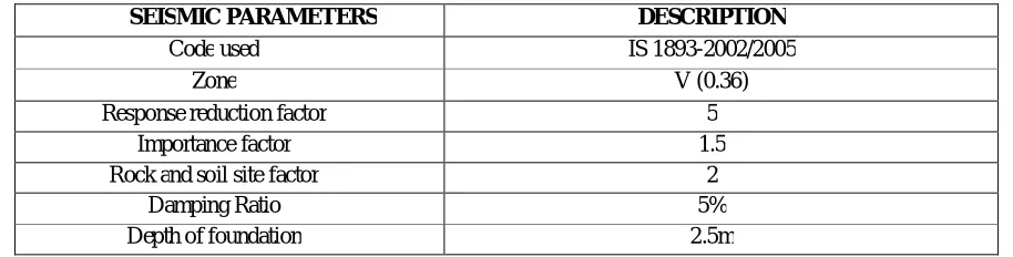
B. SEISMIC SPECIFICATIONS :
Table 2: Seismic Parameters
III. LITERATURE REVIEW
Ms. Priyanka D. Motghare [10]. has studied “Numerical studies of RCC frame with different position of floating column”. Srikanth.M.K & Yogeendra.R.Holebagilu [11] researched on “Seismic response of complex buildings with floating column for zone II and zone V”. Also Pratyush Malaviya & Saurav [12] have done “Comparitive study of effect of floating columns on the cost analysis of a structure designed on stadd pro v8i”. Ashwin Sanjay Balwaik’s [13] “Comparative Analysis of G+1 Structure With and Without Floating Column”. A theisis has been worked over [14] “Seismic analysis of multistorey building with floating column” by Sukumar Behera. Although nobody has concluded any equations in this term.
SEISMIC PARAMETERS DESCRIPTION
Code used IS 1893-2002/2005
Zone V (0.36)
Response reduction factor 5
Importance factor 1.5
Rock and soil site factor 2
Damping Ratio 5%
Depth of foundation 2.5m
Copyright to IJIRSET DOI:10.15680/IJIRSET.2015.0506165 10380
IV. OBJECTIVE OF STUDY
1) To analyze an R.C. building frame using Staad pro. Software setup.
2) To study the behavior of multistory buildings with floating columns at different locations along with seismic forces. 3) To locate the best position of Floating column in the SMRF.
V. PROBLEM STATEMENT
The entire work consists of four Cases (Case A, Case B, Case C, Case D). And these are modeled for the different position of floating columns. The results are analyzed using Node Displacement and Node Reactions as parameters.
Each model is sub-divided into different cases with different positions of floating column.
Every case is analyzed separately on the basis of node displacement and node reaction, taking the maximum values in each model.
The height of basement is kept 2.5m while height of each storey is 3m.
PRELIMINARY DATA:Table 3: Preliminary data
SPECIFICATIONS DESCRIPTION
Wall thickness (including Plaster) 300mm
Number of storey’s G+3 , G+5 , G+6 & G+10 Plan size 9m x 9m (Each grid size 3m x 3m)
Size of columns 400mm × 300 mm
Size of beams 350mm × 250 mm
Depth of slab 120mm
Floor to floor height 3.0m
Support condition Fixed
Copyright to IJIRSET DOI:10.15680/IJIRSET.2015.0506165 10381
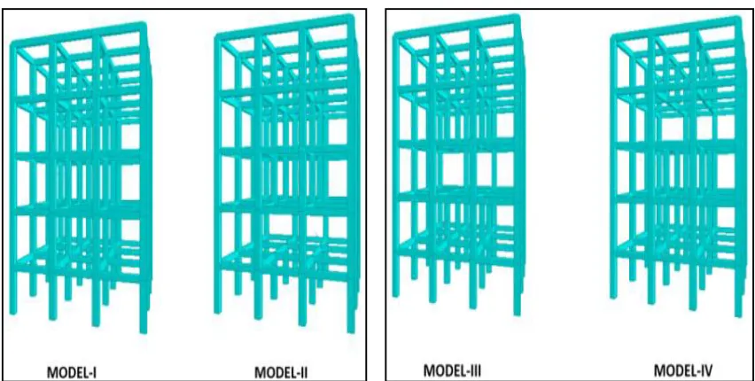
MODELS:Model I : Building with no FC
Model II : FC at 1
stfloor
Model III : FC at 2
ndfloor
Model IV : FC at 3
rdfloor & similar for all other models.
VI. M ETHODOLOGY
Steps to model and analyze the R.C.C. building frame:-
Firstly go to Run structure wizard and select bay frame. Then follow the steps given below:-
Post-processing
Modeling General
Property
Copyright to IJIRSET DOI:10.15680/IJIRSET.2015.0506165 10382
VII. RESULT AND GRAPHS
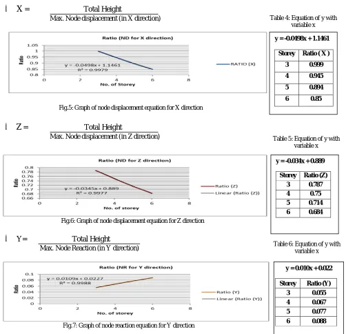
X
= Total Height
Max. Node displacement (in X direction)
Fig.5: Graph of node displacement equation for X direction
Z
= Total Height
Max. Node displacement (in Z direction)
Fig.6: Graph of node displacement equation for Z direction
Y= Total Height
Max. Node Reaction (in Y direction)
Fig.7: Graph of node reaction equation for Y direction
y = 0.010x + 0.022
Storey Ratio (Y)
3 0.055 4 0.067 5 0.077
6 0.088 y = -0.034x + 0.889
Storey Ratio (Z) 3 0.787 4 0.75 5 0.714 6 0.684 y = -0.0498x + 1.1461
Storey Ratio ( X )
3 0.999
4 0.945
5 0.894
6 0.85
Table 4: Equation of y with variable x
Table 5: Equation of y with variable x
Copyright to IJIRSET DOI:10.15680/IJIRSET.2015.0506165 10383
A. Maximum Node Displacement
Table 7: Node displacement values for case (A)
Fig. 8: Graph of node displacement for case (A)
Table 8: Node displacement values for case (B)
Fig.9: Graph of node displacement for case (B)
CASE-A (G + 3) Node displacement
Description X (91) Z (82)
MODEL-I 13.140 16.594
MODEL-II 14.414 18.349
MODEL-III 14.511 18.419
MODEL-IV 14.295 18.101
CASE-B (G + 4) Node displacement
Description X (107) Z (99)
MODEL-I 17.103 21.416
MODEL-II 18.393 23.212
MODEL-III 18.528 23.338
MODEL-IV 18.425 23.174
Copyright to IJIRSET DOI:10.15680/IJIRSET.2015.0506165 10384 Table 9: Node displacement values for case (C)
Fig.10: Graph of node displacement for case (C)
Table 10: Node displacement values for case (D)
Fig.11
:
Graph of node displacement for case (D)
CASE-C (G + 5) Node displacement
Description X(123) Z(114)
MODEL-I 21.468 26.701
MODEL-II 22.772 28.534
MODEL-III 22.932 28.694
MODEL-IV 22.884 28.611
MODEL-V 22.702 28.352
MODEL-VI 22.338 27.856
CASE-D (G + 6) Node displacement
Description X(139) Z(130)
MODEL-I 26.138 32.316
MODEL-II 27.461 34.184
MODEL-III 27.640 34.369
MODEL-IV 27.630 34.339
MODEL-V 27.521 34.183
MODEL-VI 27.286 33.858
Copyright to IJIRSET DOI:10.15680/IJIRSET.2015.0506165 10385
B. Maximum Reaction
Table 11: Maximum Reaction values for case (A)
Fig.12: Graph of Maximum Reaction for case (A)
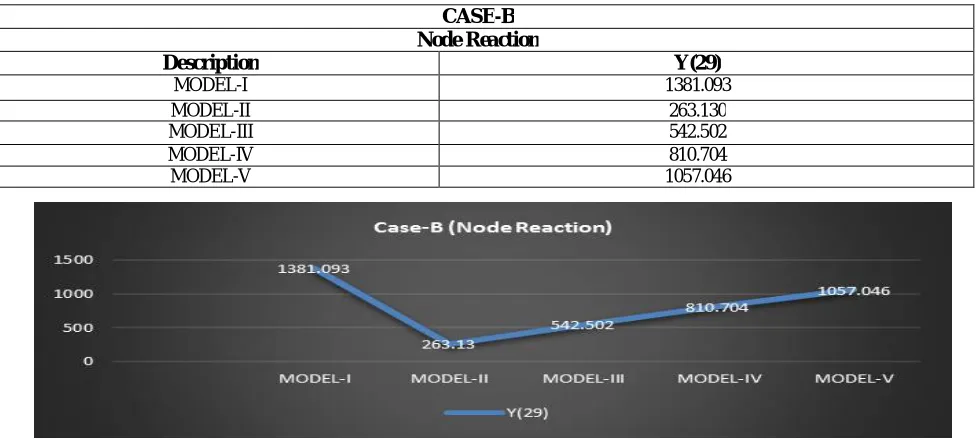
Table 12: Maximum Reaction values for case (B)
Fig.13: Graph of Maximum Reaction for case (B)
CASE-A Node reaction
Description Y(31)
MODEL-I 1148.269
MODEL-II 260.826
MODEL-III 533.706
MODEL-IV 792.934
CASE-B Node Reaction
Description Y(29)
MODEL-I 1381.093
MODEL-II 263.130
MODEL-III 542.502
MODEL-IV 810.704
Copyright to IJIRSET DOI:10.15680/IJIRSET.2015.0506165 10386 Table 13: Maximum Reaction values for case (C)
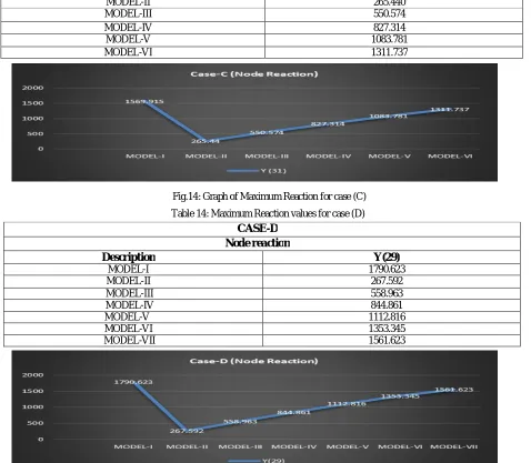
Fig.14: Graph of Maximum Reaction for case (C) Table 14: Maximum Reaction values for case (D)
Fig.15: Graph of Maximum Reaction for case (D)
CASE-C Node reaction
Description Y (31)
MODEL-I 1569.915
MODEL-II 265.440
MODEL-III 550.574
MODEL-IV 827.314
MODEL-V 1083.781
MODEL-VI 1311.737
CASE-D Node reaction
Description Y(29)
MODEL-I 1790.623
MODEL-II 267.592
MODEL-III 558.963
MODEL-IV 844.861
MODEL-V 1112.816
MODEL-VI 1353.345
Copyright to IJIRSET DOI:10.15680/IJIRSET.2015.0506165 10387
VIII. DISCUSSIONS A. Node Displacement
The structure with floating column is subjected to maximum displacement comparative to the structure without floating column.
It is found that in every case as the storey increases, the maximum node displacement is found in Model III (i.e., floating column at 1st storey).
Most reduced node displacement is found in the last model for every case, when FC is provided at the top storey.
B. Node Reaction
In every case model II has minimum reaction.
Apart from model I, last model has max. Reaction.
IX. CONCLUSION
Following conclusion can be drawn from the analysis of R.C. frame building with the different position of floating column upto 6 storeys considering the specifications taken are similar:
Since node displacement is maximum in Model III and the reaction is minimum in model II, so it shows that the floating column when provided near ground level is most hazardous. Therefore the best position of floating column is the top storey.
From the analysis, following 3 equations are found :
1. y = -0.049x + 1.146 --- (for node displacement in x-direction )
2. y = -0.034x + 0.889 --- (for node displacement in z-direction)
3. y = 0.010x + 0.022 --- (for node reaction in y-direction)
With the help of above equations we can find the maximum node displacement and the minimum node reaction for any building up to 6 storey provided that the specifications are similar.
REFERENCES
[1] Prashanth.P,Anshuman.S, Pandey.R.K, Arpan Herbert “Comparison of design results of a Structure designed using STAAD and ETABS Software” IJCSE,Volume 2, No 3, 2012
[2] Dr. Sudhir K Jain (IIT Kanpur) and Dr. H.J.Shah (M.S.University of Baroda, Vadodara) “Design Example of a Six Storey Building” IITK-GSDMA-EQ26-V3.0
[3] P.C.Varghese, “Advanced Reinforced Concrete Design”, Second Edition.
[4] Pankaj Agrawal and Manish Shrikhande “Earthquake resistant design of structure” Third Printing [5] Ashis Debashis Behera, K.C. Biswal ”3D Analysis of building frame using Staad Pro.” NIT ROURKELA. [6] IS: 456-2000(Indian Standard Plain Reinforced Concrete Code of Practice) – Fourth Revision
[7] IS: 1893-2002 (part-1) “criteria for earthquake resistant design of structures” fifth revision, Bureau of Indian Standards, New Delhi, India.
Copyright to IJIRSET DOI:10.15680/IJIRSET.2015.0506165 10388 [9] IS: 875-1987 (part-2) for Live Loads or Imposed Loads, code practice of Design loads (other than earthquake) for
buildings and structures.
[10] Ms. Priyanka D. Motghare “Numerical studies of rcc frame with different position of floating column.”
[11] Srikanth.M.K & Yogeendra.R.Holebagilu “Seismic response of complex buildings with floating column for zone -II and zone V”
[12] Pratyush Malaviya & Saurav have done “Comparitive study of effect of floating columns on the cost analysis of a structure designed on stadd pro v8i”