Artificial Intelligence Controlled
Microinverter for PV Applications
Aina Theresa Pereira 1, Maheswaran K.2
P.G. Student, Department of Electrical and Electronics Engineering, NCERC, Thrissur, India1
Assistant Professor, Department of Electrical and Electronics Engineering, NCERC, Thrissur, India2
ABSTRACT: Renewable sources of energy are becoming more popular due to environmental concerns and need for
energy. Solar energy is one of the most extensively exploited sources of effective natural energy. Microinverters are low power DC-AC converters that are attached to each solar PV panel of a solar energy system which are mainly based on flyback converter topology. In this paper, a novel single stage zeta microinverter is proposed. Zero Voltage Switching (ZVS) technique is implemented for this topology with the help of simple snubber circuit with a few passive elements and variable frequency control technique. An increment in the output voltage and reduction in the switching losses can be achieved by the implementation of Artificial Neural Networks (ANN) based controller for the closed loop control. High voltage gain is achieved by the modified inverter and thus making the low power inverter suitable for the utilization of PV applications. By the implementation of artificial intelligence based Maximum Power Point Tracking (MPPT) control technique, the Maximum Power Point (MPP) will be extracted within a reduced tracking time. Thus modified system acts as an effective interface between PV system and the AC grid.
KEYWORDS: Microinverter, Maximum power point tracking, Artificial neural network, Fuzzy logic.
I. INTRODUCTION
The global electrical energy consumption is ever growing particularly since the last few decades. This trend is expected to grow further in the future. The reserve of conventional energy sources is not sufficient to satisfy the steady increase in the energy demand. Consumption of these non-renewable energy sources leads to an increase in pollution by the emission of the greenhouse gases. Thus renewable energy gained importance. Among the various renewable resources of energy, the solar energy systems based on PV cells is the most popular source. The solar energy is clean, free from pollution, available in abundance and above all it is available to all at fairly equal manner unlike fossil fuels. It has high energy density compared to its counterparts [1].
India is a tropical country and hence solar PV power system is one of the most promising sources of power in the years to come. However, the investment cost of solar PV system is high. This high cost is mainly due to the components of the system. A PV system generally consists of a PV array, a power conditioner and a battery. Power conditioner mainly include a DC-DC converter which is followed by an inverter. The necessary isolation should be provided between input and output of the system.
PV modules generate DC which is then converted to AC by a conventional voltage source converter to connect PV modules to AC utility grid line. The latest technology is Photovoltaic AC Module (PV ACM) also named as microinverter. It is a compact and modular structure for low power PV system applications. In short these are low power inverters in the range 100-350 W [2]. It offers the highest power optimization, design flexibility and also avoids a single point of failure. It is less prone to shading effects. Nowadays a single stage flyback type utility interactive inverter is regarded as an attracted solution in PV ACM applications [3].
II. PROPOSED TOPOLOGY OF MICROINVERTER
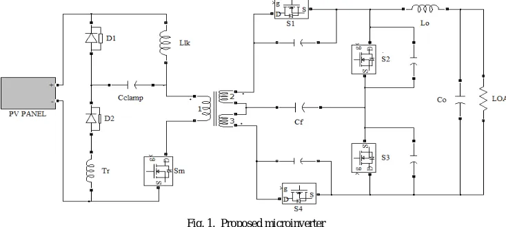
In this paper, a novel zeta microinverter with a passive snubber is proposed. Zeta converter can achieve higher bandwidth and good closed loop stability compared to flyback topologies [4]. Figure 1 shows the modified single stage zeta microinverter with regenerative snubber with passive elements. The regenerative snubber with passive electrical elements is attached to the primary side of the converter. The snubber circuit consists of a part of transformer winding Tr, a clamp capacitor, Cclamp and diodes D1 and D2.Most of the switching losses are turn-off losses as the input to the converter is low. The passive snubber along with ZVS technique implemented in the circuit will reduce the losses and noises [2] [5]. The primary side of the transformer acts like a DC-DC flyback converter with a main power switch, Sm. The secondary side of the transformer is composed of four switches (S1, S2, S3 and S4). Since the microinverter directly converts the low power DC to AC power, there is no need of a DC-DC boost converter. The high frequency flyback transformer not only generates AC power but also provides protection against any electric accident by isolating the PV array from the AC utility grid line [1].
Fig. 1. Proposed microinverter
The main switch Sm, is operated at high frequency with a variable duty cycle to produce the appropriate AC output voltage waveform. In order to ensure an AC output wave synchronized with grid, the switches on the secondary side are turned on and off in an appropriate alternate manner. For positive polarity of the energy delivered at the AC output S1 and S3 are turned on and S2 and S4 are kept off. Switches, S2 and S4 are gated to conduct and switches S1 and S3 are turned off, if the polarity required is negative.
III.MAXIMUM POWER POINT TRACKING
Fig. 2. MPPT tracking of PV panel
For transferring maximum power, the module must be operated at a’, b’, c’ instead of a, b, c. MPPT is employed to regulate the actual operation voltage of the PV panel to the voltage at MPP. This is achieved by changing the duty cycle of the converter connected to the PV system. During years, many MPPT techniques have been developed and implemented such as Perturb and Observe (P&O), Incremental Conductance, constant voltage method, fuzzy logic etc. The choice of MPPT method mainly depends on its complexity and the time taken to track the MPP [7].
The characteristics of power and current of PV cells become more complex under non-uniform and partial shading conditions. This increases the difficulty in tracking the MPP. All environmental conditions must be considered to design a MPPT technique in order to get satisfactory results. Artificial intelligence based designs are capable of producing appropriate solutions under these conditions. In this paper fuzzy logic based MPPT method is taken into consideration. 3.1 Fuzzy Logic Based MPPT
The fuzzy logic based MPPT algorithm aims to track MPP accurately and at a fast rate. The variations in atmospheric conditions and non-linearties result in uncertainties in the PV system. The Fuzzy Logic Controller (FLC), a robust controller has high capabilities to handle these states of uncertainty. Figure 3 depicts the components of FLC. Duty cycle (D) of the converter is varied till the error which is calculated becomes zero (dP/dV = 0). Only two signals from the PV module are required to design the system, thus making it simple and easy to implement. The required signals are Error signal (E) and Change in Error signal (CE). The equations (1) and (2) can be used to calculate the error and change in error [6].
( ) ( 1)
( )
( ) ( 1)
P n P n
E n
V n V n
(1)
( ) ( ) ( 1 )
The output of the FLC is considered to generate the gating pulses to the main power switch, S1 as shown in Fig. 4.The pulse width is varied such that the voltage impressed on the primary of the transformer develops a constant output at its secondary
Fig.4. Fuzzy logic MPPT technique
Membership functions are the graphical representation of the fuzzy sets. The fuzzy sets in the fuzzy logic based MPPT are error (E), change in error (CE) and the output of the FLC. The designed membership functions for inputs (E and CE) and the output is shown in Fig. 5.
(a) (b)
(c)
The rule matrix is used to describe fuzzy sets and fuzzy operators in form of conditional statements. It can be said as a simple graphical tool for mapping the fuzzy logic control system rules. The rules implemented between the input variables are listed in Table I.
Table 1 The rules of the fuzzy logic system
IV.ANNCONTROL OF CONVERTER
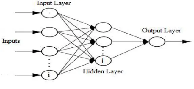
Nowadays ANN has been strongly developed both in theory and in applications. It is a machine learning approach which is a simplified model of biological nervous system. The motivation for such a concept was from the way a human brain performs the computations. By using ANN, artificial intelligence problems can be solved without creating a model of a real dynamic system. ANN involves a highly interconnected network of a large number of small processing elements called neurons. A common structure of ANN is shown in Fig. 6. These have the ability to learn and adapt under noise and uncertainty. The connections between the neurons determine the complex global behavior exhibited by them [8].
Fig. 6. Structure of ANN
Artificial neuron receives a number of inputs and has only one output. In ANN, artificial neurons are organized in layers namely input layer, hidden layer and output layer. The network receives the inputs by neurons in the input layer. The input layer communicates to one or more hidden layers which then link to an output layer. The actual processing is done in the hidden layers by a system of weighted connections [8].
to the switches at the secondary side of the transformer. The error signal is generated by comparing the actual output voltage of microinverter with the reference grid voltage. The generated error is compensated using the ANN controller. The Levenberg Marquardt Back Propagation algorithm is used to train the network. By tuning the PI or PID controllers, the data set which are used to train the ANN by various algorithm can be obtained [9]. The advantage of this back propagation is that even if it begins far from the final optimum, it succeeds in finding the solution.
V. SIMULATION RESULTS
The proposed system was simulated in MATLAB/Simulink software. MATLAB (matrix laboratory) is a multi-paradigmnumerical computing environment and fourth-generation programming language. A proprietary programming language developed by MathWorks. MATLAB allows matrix manipulations, plotting of functions and data implementation of algorithms, creation of user interfaces and interfacing with programs written in other languages, including C, C++, Java, Fortran and Python.The converter was implemented with input voltage in the range 40-50V and the grid reference voltage was considered to be 110V. The main power switch, S1 is operated at a high frequency of 60 kHz. The input to the converter is fed from a simulation model of PV system [10]. MPPT technique employing fuzzy logic is implemented for efficient utilization of the PV array. ANN based control method is implemented for improving the performance of the microinverter.
Fig. 7. Simulation of the proposed microinverter
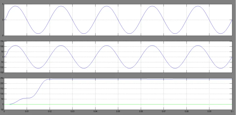
Fig. 8. Output waveforms of the proposed system
VI.CONCLUSION
A PV system with fuzzy logic based MPPT fed single stage zeta microinverter with ANN controller is proposed. The proposed converter has a snubber circuit with passive electrical elements. The proposed microinverter considered has only one switch being operated at high frequency which results in low switching losses. Soft switching is implemented which further reduces the losses especially turn-off losses. The flyback high frequency transformer not only boosts the voltage obtained from the PV panel but also provides isolation.
The output of the PV panel varies mainly with changes in solar irradiance and temperature. This uncertainty is dealt efficiently by the fuzzy logic MPPT technique. The artificial intelligence based MPPT is discussed in detail. The fuzzy logic MPPT is fast and accurate in MPP approximation. The ANN controller implemented in the system improves the performance of the converter. The control of the gate pulses given to the secondary switches of the converter through ANN logic is discussed. The THD is reduced to below 5% which is within the standard limits. The power is also increased to about 250 W. Thus, with the implementation of MPPT based on fuzzy logic and control with ANN controller, an improved performance of the proposed microinvereter is obtained.
REFERENCES
[1] Lallu Mol K Johny and Muhammedali Shafeeque K, “ PV Fed Flyback DC-AC Inverter with MPPT Control”, International Conference on
Magnetics, Machines & Drives (AICERA-2014 iCMMD), Kottayam, pp. 1-6, 2014
[2] Aniruddha Mukherjee, Majid Pahlevaninezhad and Gerry Moschopoulos, “A Novel ZVS Resonant Type Flyback Microinverter with
Regenerative Snubber”, 29th Annual IEEE Applied Power Electronics Conference and Exposition (APEC), Fort Worth, pp. 2958-2964, 2014
[3] Quan Li and Peter Wolfs, “Recent Developments in the Topologies for Photovoltaic Module Integrated Converters”, 37th IEEE Power
Electronics Specialists Conference (PESC’06), Jeju, pp. 1-8, 2006
[4] Ravi K Surapaneni and Akshay K Rathore, “A Single Stage CCM Zeta Microinverter for Solar Photovoltaic AC Module”, IEEE Journal of
Emerging and Selected Topics in Power Electronics, vol. 3, no. 4, pp. 892-900, 2015
[5] N. Kasa, T. Iida and A. K. S. Bhat, “Zero-Voltage Transition Flyback Inverter for Small Scale Photovoltaic Power System”, 36th IEEE Power
Electronics Specialists Conference (PESC’05), Recife, pp. 2098-2103, 2005
[6] Haitham Hassan, Mostafa Abel Geliel and Mahmoud Abu-Zeid, “A Proposed Fuzzy Controller for MPPT of a Photovoltaic System”, IEEE
[7] Akash Garg, R. Saida Nayak and Sushma Gupta, “ Comparison P&O and Fuzzy Logic Controller in MPPT for Photovoltaic (PV) Applications by using MATLAB/Simulink”, IOSR Journal of Electrical and Electronics Engineering, vol. 10, no. 4, pp. 53-62, 2015
[8] Haritha K. P and Albert Alexander S, ” Output Voltage Regulation Techniques for Solar Fed Cascaded Multilevel Inverter”, International Journal of Advanced Information Science and Technology (IJAIST), vol. 23, no. 3, pp. 67-73, 2014
[9] Dr. T. Govindaraj and Dhivya N. M, “Simulation Modelling on Artificial Neural Network based Voltage Source Inverter Fed PMSM”,
International Journal of Innovative Research in Electrical, Electronics, Instrumentation and Control Engineering, vol. 2, no. 1, pp. 785-792 2014
[10] M. G. Villalva, J. R. Gazoli and E. Ruppert F., ” Modelling and Circuit based Simulation of Photovoltaic Arrays”, Brazilian Journal of Power