Effect of Soil Structure Interaction in RC
Framed Building Compared To Fixed Base
Byresh A1, Umadevi R2
M.Tech in Structures, Department of Civil Engg, ACS College of Engineering, Karnataka, India1
Asst. Professor, Department of Civil Engg, ACS College of Engineering, Karnataka, India2
ABSTRACT: Soil Structure0Interaction (SSI) is the process where the soil response particles to earthquake ground motion affect the structure motion and the response of structure affects the motion of soil mass. In design companies the base of multi-storey buildings are taken as fixed and analyzed for earthquake response using provisions of IS 1893-2002 with the aid of response spectrum and time history given for soft soils in foundation. Soil structure interaction is usually carried out for soft, medium and hard soil. This study is mainly concentrated on soft soil conditions. The RC framed building of different storey height of G+10, G+20 and G+ 30 models is considered to analyze the fixed base condition and SSI base condition. The soil spring is assigned at the centre of rigidity of raft foundation for SSI models and the results are compared for different parameters for fixed base condition and SSI models. The study has used the finite element tools ETABS ver15 for modelling and for SSI analysis.
KEYWORDS: Soil structure interaction (SSI), RC building, Response spectrum analysis, Time history analysis and ETABS ver15.
I.INTRODUCTION
The most destructive of natural hazards are Earthquakes (EQ). The seismic waves are generated in the process of tremor. Seismic waves are generated in both vertical and horizontal component among which vertical component is having generally less intense than horizontal component. The record of world greatest earthquakes was happened in India in the last century.In fact, the 50% country area was considered prone to earthquake damages. The north eastern region of the entire Himalayan belt of the country will undergo great earthquakes magnitude having a value more than 8.0. The Himalayan0region and the Indo-gangetic plains, even the0peninsular India is prone to damaging0earthquakes as clearly illustrated0by the Koyna (1967), Latur (1993), and the Jabalpur (1997) earthquakes. Most structures of civil engineering will involve in different types of structural element with straight contact of ground. The successful performance of buildings are subjected to strong earthquake and drift, Base shear, Time period, Shear force and ground motions depends on their strength. The interaction of these structures, the foundations and the soil medium beneath the foundations changes the original behaviour of the structure than what is obtained from the consideration of the individual structure. The investigations have been carried out by researchers on structural behaviour of tall structures with SSI by considering many parameters like foundation type and soil conditions. Some few investigations are carried out on soil-structure interaction of tall structures under soil conditions in Indian seismic zones. Therefore, the present study has proposed tall structures with raft foundation on soft soil to study the behaviour and response for a earthquake ground motions and compared with fixed base conditions for Storey displacement, Inter storey drift and Bending moments.
II . MATERIALS & METHODS
The aim0of this0study is to analyse the comparison of fixed base structures and soil structure interaction structures. The selected model of three buildings consists of ten storeys, twenty storeys and thirty storeys are having different section components. The model is analysed only for gravity and dynamic loading. These models were analyzed using ETABS 2015. The floor height is 3.0m.The thickness of slab is considered as 125mm for all buildings. Live load for all buildings is applied on floor and roof and is taken as 3 kN/m2 and 1.5kN/m2. The floor finish load applied on floor and roof is each floor of 1.0 kN/m2 and 0.5 kN/m2. Wall load of 10 kN/m is applied on beams.
Seismic input
Seismic zone, Z(IS1893:2002, clause 6.4.2, table 2)- zone IV=0.24 Response0reduction0factor, R (IS1893:2002, clause06.4.2, table 7) = 5 Importance0factor, I (IS1893:2002, clause06.4.2, table 6) =1
Soil type (IS1893:2002, clause06.4.5, pg 16) = III (Soft soil)
TABLE 1 MATERIAL GRADES USED IN MODELLING
Structure A B C
Storeys G+10 G+20 G+30
Column(mm) 500x500 900x900 1200x1200
Beam(mm) 300x600 450x600 600x900
Grade of Concrete M25 M25 M25
Grade of Steel Fe 500 Fe 500 Fe 500
Slab thickness(mm)
125 125 125
Slabs are modelled with R.C Shell elements. Shell element is a stack of single layer membranes with different thickness and eccentricities. Shell elements can withstand bending, shear and membrane forces. For fixed conditions and for soil structure conditions the same models are considered and for soil structure interaction models raft foundations are considered of different thickness for different storeys. For considering raft foundation the design procedure of raft is calculated and punching shear for raft is calculated for raft thickness. . In both conditions the response spectrum method and time history analysis is considered.
A. Building with Fixed Base
The building of 10, 20 and 30 storey buildings are modelled with fixed base conditions, which means no linear and rotational displacements are allowed. The complete building has been modelled using appropriate elements of beams, columns and slabs in each storey.
B. Building on Raft Foundation
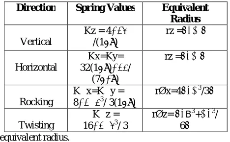
Raft foundation of 18x26 has been modelled using thick R.C. Shell elements for 10, 20 and 30 storey models, to facilitate simulation of Soil Structure Interaction effects for the clayey soil. The thickness of the raft foundation is designed by manual calculation and the various thicknesses have been adopted for different models such as 750mm for 10 storey, 1000mm for 20 storey and 1300mm for 30 storey as been adopted. The properties of soft soil have adopted and calculated, are shown in Table-6. The spring stiffness values for vertical, horizontal, rocking and twisting motions are calculated as per Richart and Lysmer model. The whole area is meshed with quad shell elements and soil springs are applied at the centre of the raft foundation.
TABLE 2 SOIL SPRING FORMULAS AS PER RICHART AND LYSMER.
Direction Spring Values Equivalent Radius
Vertical
Kz = 4 /(1−ϑ)
rz =√
Horizontal
Kx=Ky= 32(1−ϑ) /
(7−8ϑ)
rz =√
Rocking
K∅x=K∅y = 8 ∅ 3
/ 3(1−ϑ)
rØx=4√ 3/3
Twisting
K∅z = 16 ∅ 3
/ 3
rØz= √ B3 + 3/ 6 WhereK=spring stiffness, r = equivalent radius.
L= Length of0Raft and B= Width of0Raft.
TABLE 3. The soft soil spring values are applied at the centre of the raft foundation to facilitate Soil Structure Interaction. This method of applying soil springs to the raft foundation is also known as Winkler approach.
TABLE 3 CALCULATIONS OF SOIL PARAMETERS.
Soft soil parameters Calculated values
SPT No. N 10
Shear wave Velocity Vs 100xN^(1/3) 215.44 m/s
Unit weight Γ By soil test 1800 Kg/m3
Mass density Ρ γ/g 183.48 N/m3
Shear modulus G ρVs2 7570.38 KN/m2
Poisson’s Ratio µ 0.4-0.5 0.4
The calculations are done based on above formulas of richart and lysmer considering the soil parameters and the calculations are done.
TABLE 4 CALCULATIONS OF STIFFNESS SOIL SPRINGS.
Direction Notation Spring Values (kN/m)
Vertical Kz 618247.62
Horizontal Kx= Ky 468566.62
Rocking K∅x= K∅y 48034168.34
Twisting K∅z 79808202.19
III . RESULTS AND COMPARISION
(a) (b)
(c)
Flexible base condition (SSI considered) has more storey displacement compared to fixed base condition (SSI Ignored).
The percentage of Storey displacement in flexible base condition has been increased 32.6% in 10 storey, 39% in 20 storey and 41% in 30 storey more than fixed base condition.
(a) (b)
0 5 10 15
0 20 40 60
St
o
re
ys
Dispalcement in mm
Storey Dispalcement of RS in X-direction for 10 Storey
wssi
ssi 0
10 20 30
0 50 100
St
o
re
ys
Displacement in mm
Storey Dispalcement of RS in
X-direction for 20 Storey
wssi
ssi
0 10 20 30 40
0 50 100
St
o
re
ys
Displacement in mm
Storey Dispalcement of RS in
X-direction for 30 Storey
wssi
ssi
0 5 10 15
0 0.001 0.002
St
o
re
ys
Inter Storey Drift
Inter Storey Drift of RS in X-direction for 10 Storey
wssi
ssi 0
5 10 15 20 25
0 0.0005 0.001 0.0015
St
o
re
ys
Storey Drift
Inter Storey Drift of RS in
X-direction for 20 Storey
wssi
(c)
Flexible base condition (SSI considered) has more Inter Storey Drift compared to fixed base condition (SSI Ignored).
The percentage of inter storey drift in Flexible base condition has been increased 15% in 10 storey, 27% in 20 storey and 33% in 30 storey more than fixed base condition.
2.TimeHistoryAnalysisResults
(a) (b)
(c)
0 10 20 30 40
0 0.0005 0.001
St
o
re
ys
Storey Drift
Inter Storey Drift of RS in
X-direction for 30 Storey
wssi
ssi
0 5 10 15
0 50 100 150
to
re
ys
Displacement in mm
Storey Dispalcement of Time Period in X-direction for 10 Storey
wssi
ssi 0
10 20 30
0 50 100 150
St
o
re
ys
Displacement in mm
Storey Dispalcement for Time
History in X-direction for 20
Storey
wssi
ssi
0 10 20 30 40
0 50 100 150 200
St
o
re
ys
Displacement in mm
Storey Dispalcement of Time
History in X-direction for 30 Storey
wssi
Flexible base condition (SSI considered) has more displacement compared to fixed base condition (SSI Ignored) in 20 and 30 Storey but In 10 storey the displacement is less in flexible base condition.
The percentage of storey displacement in Flexible base condition has 32% less than fixed base condition for 10 Storey. The 43% of storey displacement in 20 storey and 22% of storey displacement is more in flexible base condition in 20 storey rather than fixed base condition.
(a) (b)
(c)
Flexible base condition (SSI considered) has more Inter Storey Drift compared to fixed base condition (SSI Ignored) in 20 and 30 storey but in 10 storey, the flexible base condition has less Inter Storey Drift.
The percentage of Inter Storey Drift in Flexible base condition has 33% less than fixed base condition for 10 Storey. The 40% in 20 Storey and 15% Inter Storey Drift is more in flexible base condition rather than fixed base condition.
0 5 10 15
0 0.002 0.004 0.006
St
o
re
ys
Inter Storey Drift
Inter Storey Drift of Time Period in X-direction for 10 Storey
wssi
ssi 0
10 20 30
0 0.001 0.002 0.003
St
o
re
ys
Storey Drift
Inter Storey Drift of Time
History in X-direction for 20
Storey
wssi
ssi
0 20 40
0 0.001 0.002
St
o
re
ys
Storey Drift
Inter Storey Drift of Time
History in X-direction for 30
Storey
wssi
3. Natural Time Period
Storeys Fixed Flexible
Percentage Increase In Time Period
10 1.401 1.970 28.88%
20 2.015 3.210 37.28%
30 2.183 3.678 40.65%
In Modal analysis the building is analysed as a continuous model with infinite number degrees of freedom and natural frequencies. The Natural time periods are the important factors, which affect the seismic behaviour of the structure. Natural time periods obtained from the analysis for fixed base flexible base are shown in table 5.
The time period has been varied in flexible base condition (SSI considered) rather than fixed base condition (SSI Ignored).
The percentage of time period in flexible base condition has increased 28.88% in 10 storey, 37.28% in 20 storey and 40.65% in 30 Storey more than fixed base condition.
4.Bending Moments
Bending moment contours for various rafts as obtained from dynamic analysis (Etabs software) is shown below. It is observed that the bending moments are more when soil-structure interaction is considered rather than when soil-structure is ignored (fixed base condition) it was also observed in literature [3]. The percentage increase was found to be 10-20% in column and 10- 50% in beam when SSI was considered.
4.1 Bending Moments of Columns.
STOREY S
Bending moments
for fixed base column
kN-m.
Bending moments
for flexible
base column
kN-m.
Percentage increase in bending moment(
%).
10 179.34 222.34 19.34%
20 522.24 610.32 14.43%
30 954.08 1188.82 19.74%
The Bending Moment for Column has been increased in flexible base condition (SSI considered) rather than fixed base condition (SSI Ignored).
The percentage of Bending Moment for Column in Flexible base condition has 19.34% in 10 Storey, 14.43% in 20 storey and 19.74% in30 storey more than fixed base condition for 10 Storey.
0 2 4
0 20 40
St
o
re
ys
%change in the time period
Variation in Time Period with
increase in storeys
fixed
flexible
0 500 1000 1500
0 20 40
St
o
re
ys
Bending moment kN-m
Variation of bending moment in
column with increase in storeys
fixed
4.2 Bending Moment of Beams STOREYS Bending moments for fixed base beam kN-m. Bending moments for flexible base beam kN-m. Percentage increase in bending moment(%).
10 152.35 171.46 11.15%
20 155.27 224.05 30.70% 30 285.55 539.82 47.10%
.
The Bending Moment for Beam has been increased in flexible base condition (SSI considered) rather than fixed base condition (SSI Ignored).
The percentage of Bending Moment for Beam in Flexible base condition has 11.15% in 10 Storey, 30.70% in 20 storey and 47.10% in30 storey more than fixed base condition for 10 Storey.
5. Shear Force
Shear force values and contours for various rafts from Etabs respectively are shown below. It is observed that the Shear force values are more when soil-structure interaction is considered than when soil-structure is ignored.
5.1 Shear Force of Columns
STOREYS Shear Force for fixed base Column kN. Shear Force for flexible base Column kN. Percentage increase in Shear Force kN.
10 65.78 79.37 17.12%
20 138.69 176.74 21.53% 30 268.28 356.41 24.72%
The Shear Force for Column has been increased in flexible base condition (SSI considered) rather than fixed base condition (SSI Ignored).
The percentage of Shear Force for Column in Flexible base condition has 17.12% in 10 Storey, 21.53% in 20 storey and 24.72% in30 storey more than fixed base condition for 10 Storey.
5.2ShearForceofBeams Storeys Shear Force for fixed base Beam kN. Shear Force for flexible base Beam kN. Percenta ge increase in Shear Force kN.
10 80.16 90.65 11.57%
20 96.27 139.06 30.77% 30 196.89 364.41 45.97%
0 200 400 600
0 20 40
St
o
re
ys
Bending moment kN-m
Variation of bending moment in
beam with increase in storeys
fixed
flexible
0 200 400
0 20 40
St
o
re
ys
Shear force in kN
Variation of shear force in column
with increase in storeys
fixed
flexible
0 500
0 20 40
St
o
re
ys
Shear force in kN
Variation of shear force in beam
with increase in storeys
fixed
The Shear Force for Beam has been varied in flexible base condition (SSI considered) rather than fixed base condition (SSI Ignored).
The percentage of Shear Force for beam in Flexible base condition has 11.57% in 10 Storey, 30.71% in 20 storey and 45.97% in30 storey more than fixed base condition for 10 Storey.
IV. CONCLUSIONS
Time period elongation takes place in soil structure interaction0compared to fixed base condition. The base shear is decreased due to increase in time period due to flexibilty in soil condition.
The storey displacement and inter storey drift decreases in 10 storey for time history analysis, hence the time history is well performed for tall structures.Storey drift is increased in both the cases in middle storeys showing maximum drift, When SSI is considered there is a magnification of storey drift in the middle storeys. Due to decrease in frequency of the system , the local forces (shear force, bending moment) are increased. The response of the soil structure interation tall building founded on soft soil has shown significant increase
compared to fixed base on soft soil.Significant increase in response of tall building when SSI is considered is because of flexibility induced to the base by the softness of soft soil.
Hence SSI is also important parameter while designing the tall structures under soft soil.
ACKNOWLEDGEMENTS
I am thankful to Kiran kumar K L, Structutral engineer, and Dept of Civil Engineering, Principal of ACS College of Engineering, Bangalore, Karnataka, India. My students and my beloved friends for their timely help rendered and the immense support extended for the submission of this paper.
REFERENCES
1. Dr. D. S. Prakash, M Roopa and H.G Naikar “Soil Structure Interaction Analysis on a RC Building with Raft foundation under Clayey Soil Condition” International journal of research and technology, Vol. 4 Issue 12, December-2015.
2. Bhattacharya, K., Dutta, S.C., and Dasgupta, S. (2004). “Effect of soil- flexibility on dynamic behaviour of building frames on raft foundation” Journal of Sound and Vibration, 274, pp. 111–135.
3. Bhojegowda V T and Mr. K G Subramanya “Soil Structure Interaction of Framed Structure Supported on Different Types of Foundation” International Research Journal of Engineering and Technology, Volume: 02 Issue: 05, Aug-2015.
4. G.Gazetas “Seismic design of foundation and soil-structure interaction”, First European Conference on Earthquake Engineering and Seismology, Geneva, Switzerland, 3-8 September, Paper Number: Keynote Address K7, 2006.
5. Bowles, J., Foundation Analysis and Design, 5th ed., McGraw-Hill, International Edition, 1997.
6. IS: 456-2000, “Code of Practice for Plain and Reinforced Concrete”, Bureau of Indian Standards, New Delhi, India.