Computer - Aided Evaluation of Steam Power
Plants Performance Based on Energy and
Exergy Analysis
Ahmed Noaman Ahmed Kamal El-Zayati1, Eed A. Abdel-Hadi 2, Sherif H. Taher 2, Islam H. Abdel-Aziz3
P.G. Student, Dept. of Mechanical Engineering, Shobra Faculty of Engineering, Benha University, Egypt1 Professor, Dept. of Mechanical Engineering, Shobra Faculty of Engineering, Benha University, Egypt2 Associate Professor, Dept. of Mechanical Engineering, Faculty of Engineering, Fayoum University, Egypt3
ABSTRACT:This paper aims to solve the power consumption problem by analysing the steam power plants from the energetic and exergetic viewpoint using computer application method. Most of the previous applications havesome specificitieswhich cannot be applied to anysteam power plant.Moreover, they neglect the volumetric analysis of the hydrocarbon fuel which has a considerable effect on the boiler and power plant efficiencies. So, the first author built a new computer program called Energy and Exergy Analyses (EEA) Whichcovers the shortage and overcomes the problems of the previous programs. We used it to analyse the increment problem of the fuel consumption occurred in the Cairo West Thermal Power Plant (Units 7 & 8). The results presented by EEA show that the boiler is the main source of exergy destruction due to combustion, boiling and superheating processes.Finally, we recommended some modifications to increase the power plant efficiency.
KEYWORDS: EEA, Energetic, Exergetic, analysis, Efficiency, Steam power plant.
I. INTRODUCTION
Energy is the cornerstone of the economic development, so it is bound to re-examine the energy policies and take drastic steps in order to cope with the growing energy consumption. As a result of researches on this topic, it appears that there will be a massive increment in the energy consumption which will be led by The Non-OECD (Non Organisation for Economic Co-operation and Development) countries in the next two decades [1].
One way used to overcome the power consumption problem is to study the management of power production in steam power plants. By focusing on these plants, it is found that significant part of power is lost without any benefit from it which means that companies pay much money for less power. The previous studies analysed the power plants from the first law of thermodynamics point of view which concerns with the quantity of energy. Also, many of these studies adopt the second law of thermodynamics in the analysis because it concerns with the quality of energy.
II. LITERATUREREVIEW
Sato [2] presents an introduction to the chemical thermodynamics for engineers discussing the total exergy of substances which composed of a physical part and a chemical part. Moreover, the thermodynamic laws and the aspects of energy, entropy, and exergy are covered in detail by Dincer and Rosen [3]. Furthermore, Moran [4] presented the thermal system design from the second law point of view. Also, Aljundi [5], Ameri, et al. [6] and Afifi [7] found that the main system responsible for energy destruction is the condenser and the boiler is the main system responsible for the exergy destruction. Moreover, Afifi [7] proved that using the fuel oil as the main fuel, achieving the greatest exergy efficiency of the combustion process. Moreover, Altayib [8] found that “the overall plant energetic and exergetic efficiencies increased by 20% and 12%, respectively, with cooling down the compressor inlet temperature to 10oC”. Also, he found that the major exergy loss was found in the combustion chamber. Ameri, et al. [9] found that the combustion process is the reason for the major exergy loss and the losses in the heat recovery steam generator (HRSG) come in the second place. Finally, they demonstrated that despite the output power increased by adding a duct burner to HRSG, the energy and exergy efficiencies decreased.
Ahmadi and Toghraie [10] performed energy and exergy analyses of Shahid Montazeri Power Plant using EES (Engineering Equation Solver) software. Moreover, Singh et al. [11] developed a C++ code for iterative calculations used in energy and exergy analyses of a 250MW thermal unit in Bhilai, India. Furthermore, Ahmadi and Dincer [12] developed a simulation program using Matlab software in order to find the best design parameters for Shahid Salimi gas turbine power plant in Neka, Iran. Finally, a computer program, written in Turbo Pascal, is presented by Fungtammsan, et al. [13]. The results show that the major energy destruction in the boiler is due to the energy carried out with flue gases. Finally, they emphasise that the combustion process is the main reason for the exergy destruction.
III.EEASOFTWARE AND THERMODYNAMIC ANALYSIS
The first author proposed and built a computer program, EEA, to get the energy and exergy analyses of the steam power plants. It is written using an Object Oriented Programming language (Microsoft Visual C#) with the aid of Microsoft Excel and SAP Crystal Reports. Moreover, the visual basic code of X-Steam Tables is converted into visual C# code and used to get the thermodynamic properties of the water and steam streams. Finally, a new code is added to get the specific entropy of the points in the wet region of the h-s water diagram.
EEA covers the shortage and overcomes the problems of the previous programs. It has an interactive form containing many systems which not mentioned in the earlier programs. Moreover, it is applicable to any steam power plant. It covers a wide range of hydrocarbon fuels which used in the combustion process then uses them to generate the fuel model. It calculates the reversible, isentropic and the actual power of main equipment of the plant. EEA calculates the thermal properties of all supplied streams. It shows the thermal efficiency of the power plant based on the lower and higher heating values. Furthermore, it shows the exergetic destruction and efficiency of the power plant. It lists the power and exergy destruction (loss) in many systems in the power plant. It presents the exergetic efficiency and destruction of each system and makes a comparison among them. As the boiler is a major and important system in the power plant, EEA presents its results in detail. It shows the gross and fuel energy efficiencies of the boiler. It shows the generated fuel model and its specifications. It presents the combustion process formula of the fuel in the stoichiometric and actual cases. It lists the air-fuel ratio and the adiabatic flame temperature. It produces the results in tables and charts to facilitate the analyses of these results. Finally, EEA is used to study the energy and exergy analysis of the Cairo West Thermal Power Plant (Units 7 & 8) in order to show its capabilities.
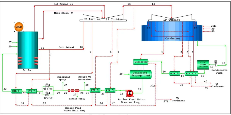
steam turbine which rolls the generator to produce the electrical power. The condensed steam is collected and stored at the bottom of the condenser in the hot well to start the feed-water cycle again.
Fig. 1: Power plant layout.
We made energy and exergy model of the power plant and presented it in Table 1. It presents the thermodynamics model of the main systems of the power plant. It shows thefueland the product of each system. Moreover, it shows the exergetic destruction and the exergetic efficiency of these systems. Furthermore, the isentropic, theoretical and reversible power of pumps and turbines are supplied. Finally, the power plant net power, thermal and exergetic efficiency are listed.
Table 1: Thermodynamics model of main components of Cairo West Thermal Power Plant (Units 7 & 8) System Thermodynamics Model System Thermodynamics Model
Turbine
η =Ẇ
Ẇ
Fuel = Ẇ , Product = Ẇ
̇= ̇ − ̇ , = ̇
̇
High-Pressure Turbine
̇ = ̇ . − ̇ . , − ̇ . ,
̇ = ̇ − ̇ − ̇
Ẇ = ṁ . h −ṁ . h −ṁ . h
Intermed iate Pressure Turbine
̇ = ̇ . − ̇ . ,
− ̇ . ,
̇ = ̇ − ̇ − ̇
Ẇ = ṁ . h −ṁ . h −ṁ . h
Low-Pressure Turbine
̇ = ̇ . −( ̇ . , + ̇ . ,
+ ̇ . , + ̇ . ,
+ ̇ . , )
̇ = ̇ − ̇ − ̇ − ̇ − ̇ − ̇
Ẇ = ṁ . h −ṁ . h −ṁ . h −ṁ . h
Pumps
= ̇̇
Fuel = Ẇ , Product = Ẇ
̇= ̇ − ̇ , = ̇̇ Condens ate Pump ̇ = ̇ . , − ̇ . ̇ = ̇ . − ̇ .
Ẇ = Eẋ −Eẋ
Feed-water Booster Pump ̇ = ̇ . , − ̇ . ̇ = ̇ . − ̇ . ̇ = ̇ − ̇ Feed-water Main Pump ̇ = ̇ . , + ̇ . , − ̇ . ̇ = ̇ . + ̇ . − ̇ .
Ẇ = Eẋ + Eẋ −Eẋ
Heater 1
= ̇ − ̇
= ̇ − ̇
̇= ̇ + ̇ −( ̇ + ̇ )
η =Eẋ −Eẋ
Eẋ −Eẋ
Heater2
= ̇ + ̇ − ̇
= ̇ − ̇
̇= ̇ + ̇ + ̇ −( ̇ + ̇ )
η = Eẋ −Eẋ
Eẋ + Eẋ −Eẋ
Heater3
= ̇ − ̇
= ̇ − ̇
̇= ̇ + ̇ −( ̇ + ̇ )
η =Eẋ −Eẋ
Eẋ −Eẋ
Deaerato r = ̇ + ̇ + ̇ = ̇ − ̇ ̇= ̇ + ̇ + ̇ + ̇ − ̇ = ̇ ̇ − ̇ + ̇ +∑ ̇ Heater5 = ̇ + ̇ − ̇ = ̇ − ̇ ̇= ̇ + ̇ + ̇ −( ̇ + ̇ ) = ̇ ̇ − ̇ + ̇ − ̇ Heater6 = ̇ + ̇ − ̇ = ̇ − ̇ ̇= ̇ + ̇ + ̇ −( ̇ + ̇ ) = ̇ ̇ − ̇ + ̇ − ̇ Heater7 = ̇ + ̇ − ̇ = ̇ − ̇ ̇= ̇ + ̇ + ̇ −( ̇ + ̇ ) = ̇ ̇ − ̇ + ̇ − ̇ Heater8 = ̇ − ̇ = ̇ − ̇ ̇= ̇ + ̇ −( ̇ + ̇ )
= ẋ −Eẋ
Eẋ −Eẋ
Boiler = ̇ , + ̇ + ̇ − ̇ , , = ̇ + ̇ − ̇ + ̇ + ̇ + ̇ ) ̇= ̇ , + ̇ + ̇ + ̇ + ̇ + ̇ + ̇ −( ̇ + ̇ + ̇ , ) η
=Eẋ + Eẋ −(Eẋ + Eẋ + Eẋ + Eẋ )
Ẇ , + Eẋ + Eẋ −Eẋ ,
Where,
CV Calorific value kJ/kg Q̇ Heat rate loss in the condenser kW
Eẋ Exergy rate kW Ẇ Power kW
Eẋ , Exergy rate of air heater exit gases kW Ẇ Mechanical calculated power without coupling
and electrical losses in generator
kW
h Specific enthalpy kJ/kg Ẇ Consumed power by machines such as pumps, fans and compressors
kW
İ Exergy destruction rate (Irreversibility)
kW η Efficiency according to first law of thermodynamics (Energy efficiency) ṁ Mass flow rate kg/s,
t/h η
Efficiency according to second law of thermodynamics (Exergy efficiency)
IV.RESULTS AND DISCUSSIONS
We supplied the operating parameters of the power plant at 50% load (175 MW) in 2011 to the EEA. It summarises the power plant energy and exergy results presenting them in Figure 2. It shows the exergy efficiency and destruction of the power plant. Moreover, it presents the generated power, consumed power and net generated power of the power plant. Furthermore, it shows the thermal efficiency of the power plant based on the lower and higher heating values.
Fig. 2: Energy and exergy summary of the power plant.
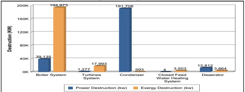
Figure 3provides the energetic and exergetic loss, destruction, of the main systems. It reveals that despite the condenser is the main reason for energy loss in the power plant, its exergy destruction is insignificant. Moreover, it shows that the boiler is the main source of exergy destruction despite its low energy loss.
EEA presents the exergy analyses of the main systems in the power plant inFigure 4. It shows that the turbine system has the highest exergetic efficiency of the power plant. Moreover,it reveals that the boiler system has the lowest exergetic efficiency of the power plant.
Fig. 4: Exergetic efficiency of main systems.
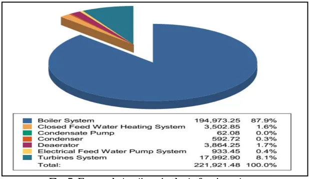
The pie chart shown in Figure 5 shows that 195 MW of exergy destructed in the boiler making it the major system responsible for theexergetic destruction in the power plant. Moreover, it shows that the exergetic destruction of the turbine system is significant compared to other systems in spite of its high efficiency.
Fig. 5: Exergy destruction pie chart of main systems.
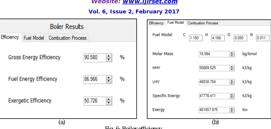
(a) (b) Fig. 6: Boiler efficiency.
In order to compare the exergetic efficiencies of the boiler processes and subsystems, EEA generates a bar chart as shown in Figure 7. It shows that the air preheater has the highest exergetic efficiency in the boiler. It reveals that the boiling and superheating process has the lowest exergetic efficiency in the boiler.
Fig. 7: Boiler exergetic efficiency.
Fig. 8: Boiler exergy destruction pie chart.
We made a comparison between the power plant operating parameters at half load inFigure 9. it illustrates the exergy destruction of the boiler processes which recorded in different years. It shows that, in 2013, there is a dramatic increment in the fuel flow rate, the exergetic destruction of the combustion process and boiling andsuperheating processes.
As a result of using the backup fuel (Oil number 6) instead of the main fuel (Natural gas) for a long time, many problems occur in the boiler such as:
Corrosion occurs in the burner impeller and gas spuds. Some burners are totally damaged.
Ashes and deposits from the fuel oil combustion process fouled the heating surface of the boiler tubes.
Ashes and deposits clogged the spaces between the tubes as presented.
Some tubes displaced from its original locations clogging the product gases pass.
Fig. 9: Exergy destruction in boiler processes.
2011 2013 2015
Boiling and Superheating
Process Destruction (MW) 82.71 126.98 90.40
Combustion Process
Destruction (MW) 109.26 121.32201 114.14
Fuel Flowrate (t/h) 30.61 35.73 32.04
25 30 35 40 45 50
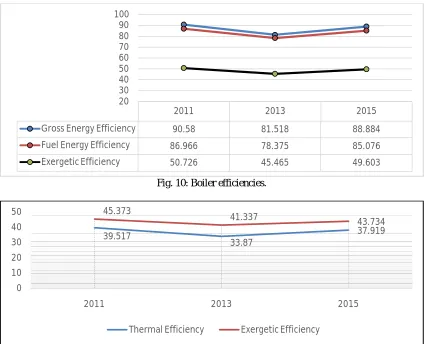
the gross energy, fuel energy and exergetic efficiency of the boiler.Finally, the overall power plant exergetic efficiency decreased as shown in Figure 11.
Fig. 10: Boiler efficiencies.
Fig. 11: Power plant efficiency in different years.
In 2015, the unit was shut down for a major overhaul. Damaged parts in the burners are replaced. Furthermore, chemical cleaning of the tubes has been done removing much of the deposits. Finally, some tubes are displaced close to its original positions.
As a result of these procedures, the exergetic destruction of the combustion process and the boiling and superheating process decreased in 2015 as shown in Figure 9. This decrement led to a significant decrement in the boiler exergy destruction which increased the thermal and exergetic efficiencies of the boiler as shown in Figure 10. Finally, the overall power plant thermal and exergetic efficiencies increased as shown in Figure 11.
V. CONCLUSION AND RECOMMENDATIONS
The first author proposed and built a computer program (EEA). We used it to evaluate the performance of the Cairo West Thermal Power Plant of different operating parameters. It showed that the condenser is the main system responsible for power (energy) loss in the power plant and the boiler comes in the second place. Furthermore, it presented the turbine system as the highest exergetic efficiency system and the boiler system as the lowest exergetic
2011 2013 2015
Gross Energy Efficiency 90.58 81.518 88.884
Fuel Energy Efficiency 86.966 78.375 85.076
Exergetic Efficiency 50.726 45.465 49.603
20 30 40 50 60 70 80 90 100
39.517
33.87
37.919 45.373
41.337 43.734
0 10 20 30 40 50
2011 2013 2015
efficiency system in the power plant. Moreover, EEA provided a strong evidence that the boiler is the main source of exergy destruction with 195 MW destruction due to combustion, boiling and superheating processes. Finally, it showed that, in 2013, the exergeticdestruction in the boiling and superheating processes increased dramatically, which led to a gigantic destruction in the boiler system and the power plant.
In order to decrease the exergetic destruction in the boiler and increase the boiler and the power plant efficiency, we recommend to:
1. Replace the burners’ impellers with new ones with greater spaces to prevent ashes and deposits from clogging these spaces.
2. Supply air pipe to the gas spuds to cool it down, when using fuel oil in the combustion process.
3. Operate the upper row of burners with natural gas in the case of mixed fire operation. Therefore, thehigher flame temperature of the natural gas burners will achieve a complete combustion of the unburned fuel oil products.
4. Make a chemical test for the fuel oil additive dosing substance to ensure that it is suitable for the fuel oil chemical composition.
In addition to these modifications, we need to upgrade the EEA to cover more systems such as; Gas Turbine system, Combined Power Plants, Geo Thermal Power Plants and Solar Power Plants. Furthermore, it is important to cover more fuels such as; Fuel oil number 6 (Mazout). Moreover, further thermodynamic analyses of the Cairo West Thermal Power Plant should be performed in these cases:
Using fuel oil as the main fuel
Using mixed firing
Finally, it is important to create a power plant designer, which allows users to supply the target electric load generation required and it will generate a power plant design and present the plant components with their technical specifications.
REFERENCES
[1] U. States. and E. I. Administration., “Official energy statistics from the U.S. government”, Energy Information Administration, Washington, DC.
[2] Sato N., “Chemical Energy and Exergy: An Introduction to Chemical Thermodynamics for Engineers”, Elsevier Science & Technology Books, 2004.
[3] Dincer, I., Rosen, M.A., “Exergy, Energy, Environment And Sustainable Development”, 2nd ed. Elsevier, 2013.
[4] Moran, M. J., “Fundamentals of Exergy Analysis and Exergy-Aided Thermal Systems Design in Thermodynamic Optimization of Complex Energy Systems, A. Bejan and E. Mamut”, Springer, pp. 73–92, 1999.
[5] Aljundi, I. H., “Energy and exergy analysis of a steam power plant in Jordan”, Applied Thermal Engineering, vol. 29, no. 2–3, pp. 324–328, Feb. 2009.
[6] Ameri, M., Ahmadi, P., and Hamidi, A., “Energy, exergy and exergoeconomic analysis of a steam power plant: A case study”, International Journal of Energy Research, vol. 33, no. 5, pp. 499–512, Apr. 2009.
[7] Afifi, I. H., “Theoretical Analysis and Practical Application of Exergy for a Co-Generation Plant at Different Operating Conditions”, Cairo University, 2002.
[8] Altayib, K., “Energy, Exergy and Exergoeconomic Analyses of Gas-Turbine Based Systems”, University of Ontario Institute of Technology, 2011.
[9] Ameri, M., Ahmadi, P., and Khanmohammadi, S., “Exergy Analysis of a 420 MW Combined Cycle Power Plant”, International Journal of Energy Research, vol. 32, no. 2, pp. 175–183, Feb. 2008.
[10] Ahmadi, G. R., and Toghraie, D., “Energy and Exergy Analysis of Montazeri Steam Power Plant in Iran”, Renewable and Sustainable Energy Reviews, vol. 56, pp. 454–463, Apr. 2016.
[11] Singh, S., et al., “Exergy Analysis of Steam Power Plant for Different Grades of Coal”, National Institute Of Technology, Raipur, 2012. [12] Ahmadi, P., and Dincer, I., “Thermodynamic and Exergoenvironmental Analyses, and Multi-Objective Optimization of a Gas Turbine Power
Plant”, Applied Thermal Engineering, vol. 31, no. 14–15, pp. 2529–2540, 2011.