a
Corresponding author: [email protected]
Development of Mode Conversion Waveguides at KIT
Jianbo Jin1,a, Gerd Gantenbein1, John Jelonnek1,2 , Tomasz Rzesnicki1, and Manfred Thumm1,2 Karlsruhe Institute of Technology (KIT)
1
Institut für Hochleistungsimpuls-und Mikrowellentechnik (IHM), D-76131 Karlsruhe, Germany 2
Institut für Höchstfrequenztechnik und Elektronik (IHE), D-76131 Karlsruhe, Germany
Abstract.The development of mode conversion waveguides (launchers) for high power gyrotrons has gone through three stages at KIT. Formerly, harmonically deformed launchers have been used in the series gyrotrons developed for the stellarator W7-X. In 2009, a numerical method for the analysis and synthesis of mirror-line launchers was developed at KIT. Such a launcher with adapted mode-converting mirrors for a 2 MW TE34,19
-mode, 170GHz coaxial-cavity gyrotron has been designed and tested, and also a mirror-line launcher for the 1MW EU ITER gyrotron has been designed. Recently, based on the Helmholtz-Kirchhoff integral theorem, a novel numerical method for the synthesis of hybrid-type gyrotron launchers has been developed. As an example, TE32,9 mode launchers operating at 170GHz that have been designed using the three different
methods are being compared.
1 Introduction
As the highest-power coherent millimeter wave sources, gyrotrons are widely employed for Electron Cyclotron Resonance Heating (ECRH) and Current Drive (CD) in thermonuclear fusion plasma experiments. For high power gyrotrons operating in very high order cavity modes, internal Quasi-Optical (Q.O.) mode converters are used to transform the operating cavity mode into a fundamental Gaussian wave beam in order to reduce losses in the transmission of the gyrotron output power. An internal Q.O. mode converter consisting of an oversized open-ended smooth-wall circular waveguide launcher and a set of focusing mirrors with quadratic surface contour function was first proposed and demonstrated by Vlasov et al. [1,2]. In a Vlasov-type launcher, the power density on the wall is uniform, the fields at the edges of cuts are relative strong, the Gaussian mode content in the wave beam radiated from the launcher amounts to about 80%, while the remaining 20% of the radiation propagate at relatively large angles to the beam direction because of wave scattering and diffraction at the edges of the cuts, and are usually lost in open transmission lines. Launchers with helical, harmonically deformed waveguide wall were originally proposed and demonstrated in Ref. [3]. In order to transform a high-order cavity mode into a mode mixture forming a Gaussian-like wave beam and to achieve low fields at the edges of the launcher cuts, the launcher wall is harmonically deformed to bunch the wave beam. A
method to synthesize the helical harmonic perturbation amplitudes has been developed to improve the Gaussian mode content of the wave beam at the aperture and to depress the field at the cuts [4]. In 2006, by use of the Huygens’ principle, a numerical method was developed for the analysis and synthesis of oversized mirror-line launchers for high power gyrotrons [5]. Later in 2009 a completely different numerical method for the analysis and synthesis of the fields in such oversized mirror-line launchers has been developed at KIT [6]. Recently, based on the Helmholtz-Kirchhoff integral theorem, a novel numerical method for the synthesis of hybrid-type oversized launchers has been developed [7].
2 Development of launchers at KIT
For an operating gyrotron cavity mode, the azimuthal radiation width angle α can be defined as α=2arccos(Rc/R), where Rc and R are the caustic and
launcher radius respectively. In the case that the ratio ξ=2π/α is approximately an integer (e.g. 3 for typical conventional cylindrical cavity gyrotron modes like TE28,8), a harmonically deformed launcher employing a
helical curvature perturbation for longitudinal and a helical triangular deformation for azimuthal bunching can be designed to provide an RF beam with high Gaussian mode content at the launcher aperture. The launcher aperture is defined as the last Brillouin zone as shown in Figure 1(b), the first bundle outside the cut. Such
harmonically deformed launchers have been used in the series gyrotrons for the stellarator W7-X operating in the TE28,8 mode at a frequency of 140GHz [8]. As an another
example, a harmonically deformed launcher has been designed to transform the TE32,9 mode (α≈124.4degree)
operating at 170GHz. The wall profile and the field distribution on the launcher wall are shown in Figure 1 (unwrapped wall). The smooth-wall waveguide section after the corrugated region provides the appropriate phasing of the generated mode-mixture at the radiating launcher aperture. The results of the mode matching analysis reveal that the Fundamental Gaussian Mode Content (FGMC) η is about 96.4% at the aperture.
(a)
(b)
Figure 1. Wall profile (a) of the helically corrugated TE32,9
-mode launcher and the field distribution (b) on the launcher wall. The edges of the launcher aperture (white lines) and cut (red lines) are indicated.
A TE34,19-mode, 170GHz, 2MW, CW, coaxial-cavity
gyrotron was originally considered by the EU home team for the ECRH&CD system of the ITER tokamak. Firstly, a harmonically deformed launcher has been designed and simulation results show that the conversion efficiency of the TE34,19 mode to a fundamental Gaussian wave beam is
only about 86% at the launcher aperture [9]. For the TE34,19 mode, the angle α≈2π/2.53, so that the TE34,19
mode cannot be transformed into a Gaussian-like wave beam with a high conversion efficiency by a harmonically deformed launcher. Therefore a numerical method for the synthesis of mirror-line launchers has been developed at KIT [6]. This method is completely different from the numerical method presented in ref [5].
In the method shown in ref [5], 1) the analysis of the field on the launcher wall is based on the Kirchhoff-Huygens integral; 2) an amplitude distribution which
covers several Brillouin zones on the launcher wall is used as the target function in the optimization of the launcher wall profile; 3) the wall profile is synthesized on each Brillouin zone one by one, and the wall deformation defined on a Brillouin zone is calculated according to the phase correction, where the phase correction is the sum of the phases of the forward propagated field and that of the backward propagated field on the Brillouin zone.
In the method presented in ref [6], a) the method for the analysis of the field on the launcher wall is based on the scalar diffraction equation corresponding to the theorem of Helmholtz and Kirchhoff [10]; b) an ideal Gaussian distribution is injected into the launcher aperture, and the corresponding ideal field with desired amplitude and phase distributions defined on the launcher aperture is used as the target function in the launcher optimization; c) an error function defined on the launcher aperture is calculated according to the forward propagated field and the ideal field distribution, and the error function is backward propagated to cover the whole launcher, and then the deformation on the whole launcher wall can be obtained in terms of the backward propagated error function. The procedure of the numerical method presented in ref [6] is shown in Figure 2.
Figure 2.Optimization procedure for mirror-line launchers.
(a)
(b)
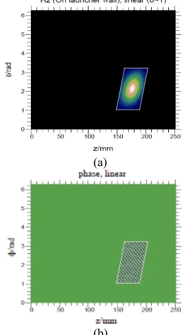
Figure 3. Target function ut for the optimization of the TE32,9-mode mirror-line launcher: amplitude distribution (a)
and phase pattern (b) at the launcher aperture (white lines).
Input Forward propagation, field distribution u f at launcher aperture
Error function E (uf and target function ut defined on the launcher aperture)
Error function E, backward
A mirror-line launcher has been designed for the 170GHz, 2MW, TE34,19-mode coaxial-cavity gyrotron in
terms of the numerical synthesis method described above [6]. The simulation results show that the FGMC of the RF beam is about 96.3% at the launcher aperture [6], which is in good agreement with low-power and high-power experimental results [11]. Hence, the limitation of the ratio ξ to be approximately an integer has been overcome in mirror-line launchers.
A mirror-line launcher has also been designed for the TE32,9-mode, 170GHz, 1MW EU ITER gyrotron
which is currently under development in Europe [12, 13]. The ideal Gaussian distribution used as the target function on the launcher aperture in the optimization of the launcher is shown in Figure 3. The wall profile of the mirror-line launcher and the field distribution on the launcher wall are shown in Figure 4. The FGMC of the RF beam is calculated to be about 98.43% at the launcher aperture.
(a)
(b)
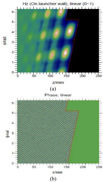
Figure 4. Wall profile (a) of the TE32,9-mode mirror-line
launcher and the field distribution (b) on the launcher wall. The edges of the launcher aperture (white lines) and cut (red lines) are indicated.
Recently, a new numerical method for launcher design has been developed [7]. The forward propagated field distribution on the launcher is analyzed based on the scalar diffraction equation corresponding to the theorem of Helmholtz and Kirchhoff [6, 10]. The key point of the new method is to artificially generate a field distribution on the complete launcher wall as a target function. A set of 9 modes given in Table 1 [8,14] can be used to compose such an ideal field distribution. The wall profile ΔR of the launcher is iteratively optimized according to
the phase difference between the forward propagated field on the launcher wall and the target function. The procedure of this numerical method is shown in Figure 5. A launcher for the TE32,9 mode at 170GHz has also been
designed in terms of this new method. According to Table 1, the target function is generated as shown in Figure 6. The wall profile and the field distribution are shown in Figure 7. Due to the modified target function, the initial phase is shifted by 2.17 rad. The FGMC of the RF beam is calculated to be 98.66% at the launcher aperture.
Table 1.Relative power of a set of the satellite modes to compose the field distribution on the launcher wall at
the radiating cut [8,14].
Figure 5. Procedure of the new numerical method for the synthesis of launchers based on the Helmholtz-Kirchhoff integral theorem.
(a)
(b)
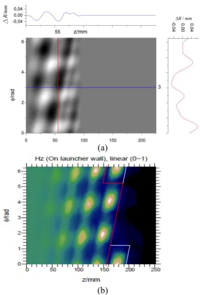
Figure 6. Target function ut for the optimization of the TE32,9-mode launcher using the new numerical method:
amplitude distribution (a) and phase pattern (b). The cut of the launcher is indicated (red lines).
TEm-2,n+1
1/36
TEm+1,n
1/9
TEm+4,n-1
1/36 TEm-3,n+1
1/9
TEm,n
4/9
TEm+3,n-1
1/9 TEm-4,n+1
1/36
TEm-1,n
1/9
TEm+2,n-1
1/36
Input Forward propagation, field distribution uf on whole launcher wall
(a)
(b)
Figure 7. Wall profile (a) of the TE32,9-mode launcher
designed in terms of the new method and the field distribution (b) on the launcher wall. The edges of the launcher aperture (white lines) and cut (red lines) are indicated.
3 Comparisons
From the discussion in Section 2 and comparing the mirror-line launcher shown in Figure 4 to the harmonically deformed launcher illustrated in Figure 1, it is evident that the mirror-line launcher can provide a Gaussian-like wave beam with higher FGMC than that in the harmonically deformed launcher. As shown in Figure 5, in the new numerical method based on the Helmholtz-Kirchhoff integral theorem, just the forward propagated field needs to be calculated, whereas in the optimization of a mirror-line launcher according to [6], the forward propagated field and the backward propagated error function should be calculated as shown in Figure 2. From Figure 7 one can find that the wall deformation in the area 0mm<z<50mm looks very similar to a harmonically deformed launcher whereas in the area 50mm<z<100mm it is similar to the perturbation in a mirror-line launcher. So the wall profile of this hybrid-type launcher is somewhat a combination of harmonic and mirror-line deformation. Table 2 presents the comparison of the deformation area, ΔR and the FGMC of the harmonically deformed launcher, the mirror-line launcher, and the hybrid-type launcher designed using the new numerical method.
4 Conclusions
Three kinds of oversized launchers for quasi-optical output couplers of high power gyrotrons have been developed at KIT. Helically deformed launchers with harmonic wall perturbations have been used in the 1 MW, 140 GHz series gyrotrons for the stellarator W7-X and have been verified in low and high power experiments. A mirror-line launcher was developed for a 2 MW, 170GHz coaxial-cavity gyrotron. Again the experimental results of cold and hot measurements reveal a good agreement with the simulation results. A mirror-line launcher has also been designed to provide a high theoretical conversion efficiency of 98.43% from the cavity mode of the 1MW, 170GHz, continuous wave EU ITER gyrotron to a fundamental Gaussian distribution. Based on the
Helmholtz-Kirchhoff integral theorem, a new numerical method for the synthesis of oversized launchers for high power gyrotrons has been developed. The wall profile of the hybrid-type launcher designed in terms of the new method looks like a combination of harmonically deformed launcher and mirror-line launcher.
References
1. S. N. Vlasov and I.M. Orlova, Radiophysics & Quantum Electronics 17,115 (1974).
2. S. N. Vlasov. L.I. Zagryadskaya, and M.I. Petelin, Radio Eng. & Electron Physics 20, 14 (1975). 3. G. G. Denisov, A. N. Kuftin, V. I. Malygin, N. P.
Venediftov, D. V. Vinogradov, and V. E. Zapevalov, Int. J. Electron. 72, 1079, (1992).
Table 2.Comparison of launchers, launcher parameters are the same:
Radius=20.6mm, launcher length=189.67mm, length of straight cut=40.3mm, operating at the TE32,9mode, 170GHz.
Launcher type deformation area
(z/mm)
Deformation (ΔR/mm)
FGMC (η) Harmonically deformed launcher
(Figure 1)
0<z<80.0 -0.062<ΔR<0.062 96.4%
Mirror-line launcher (Figure 4)
0<z<189.67 -0.05<ΔR<0.095 98.43%
Hybrid-type launcher (Figure 7)
4. J. Neilson, IEEE Trans. on Plasma Science 34 (3), 635 (2006).
5. A. V. Chirkov, G. G. Denisov, M. L. Kulygin, V. I. Malygin, S. A. Malygin, A. B. Pavel’ev, and E. A. Soluyanova, Radiophysics & Quantum Electronics 49 (5), 344 (2006).
6. J. Jin., M. Thumm, B. Piosczyk, S. Kern, J. Flamm, and T. Rzesnicki, IEEE Trans. on Microwave Theory & Techniques 57 (7), 1661 (2009).
7. J. Jin., G. Gantenbein, J. Jelonnek, and M. Thumm, “A numerical method for the synthesis of highly oversized waveguide mode converters based on the Helmholtz-Kirchhoff integral theorem”, to be submitted to IEEE Trans. on Antennas & Propagation for publication.
8. M. Thumm, X. Yang, A. Arnold, G. Dammertz, G. Michel, J. Pretterebner, D. Wagner, IEEE Trans. on Electron Devices 52 (5), 818 (2005).
9. J. Jin, M. Thumm, B. Piosczyk, T. Rzesnicki, IEEE Trans. on Microwave Theory & Techniques 54 (3), 1139 (2006).
10. M. Born and E. Wolf. Principles of Optics. Pergamon Press, Oxford, United Kingdom, 6th ed., 377 (1993).
11. T. Rzesnicki, B. Piosczyk, S. Kern, S. Illy, J. Jin, A. Samartsev, A. Schlaich, and M. Thumm, IEEE Trans. on Plasma Science 38 (6), 1141 (2010).
12. J. Jin, J. Flamm, J. Jelonnek, S. Kern, I. Pagonakis, T. Rzesnicki, and M. Thumm, IEEE Trans. on Plasma Science 41 (10), 2748 (2013).
13. J. Jelonnek, F. Albajar, S. Alberti, K. Avramidis, P. Benin, T. Bonicelli, F. Cismondi, V. Erckmann, G. Gantenbein, K. Hesch, J.-P. Hogge, S. Illy, Z.C. Ioannidis, J. Jin, H. Laqua, G.P. Latsas, F. Legrand, G. Michel, I.G. Pagonakis, B. Piosczyk, Y. Rozier, T. Rzesnicki, I.G. Tigelis, M. Thumm, M.Q. Tran, and J.L. Vomvoridis, IEEE Trans. on Plasma Science 42 (5), 1135 (2014).
14. A. A. Bogdashov and G. G. Denisov, Radiophysics & Quantum Electronics 47 (4), 283 (2004).