European Commission Joint Research Centre (JRC), Institute for the Protection and Security of the Citizen (IPSC), European Laboratory for Structural Assessment (ELSA), via E. Fermi 2749, 21027 Ispra (VA), Italy
Abstract. Critical infrastructures may become the target of terrorist bombing attacks or may have to withstand explosive loads due to accidents. The impulsive load connected to explosions is delivered to the structure in a few milliseconds forcing it to respond or fail in a peculiar mode. With reference to the above scientific framework this work presents an innovative apparatus designed and developed at the European Laboratory for Structural Assessment to reproduce a blast pressure history without using explosives. This apparatus is practically a hybrid nitrogen-spring-driven actuator that accelerates masses of up to 100 kg to a maximum velocity of about 25 m/s that impact against the tested structure. The pressure-load history applied to the structure is modulated and reshaped using appropriate layers of elastic soft materials (such as polymeric foams) placed between the specimen and the impacting masses. Specific instrumentation has extensively been utilised to investigate the blast simulator performance and to precisely measure the pressure loads applied to the specimen. A series of tests on real scale reinforced concrete beams/columns (250×250×2200 mm) has been performed to efficiently assess the performance and potentiality of the new blast simulator. Results are under evaluation. In addition to the experimental work, a series of numerical simulations by means of the explicit FEM code EUROPLEXUS have been carried out to support and improve the equipment design.
1. Introduction
Critical infrastructures in fields such as energy, health, communication, government, transport etc. are made of physical structures, or are housed in physical structures. Such structures may naturally become the target of terrorist bombing attacks. Measures to protect them will certainly be taken, involving prevention, intelligence, detection, deterrence etc., but if everything fails, it is very important that the mechanical structure itself mitigates some effects of the explosion and maintains certain functionalities.
A typical pressure wave curve (which eventually will load a structure) at some distance from an explosion is shown in Fig. 1. Its main characteristics concerning damaging effects on structures are the magnitude of the overpressure, the duration of the positive phase and especially its positive impulse, i.e., the area under the curve over the positive phase. This impulsive load will be delivered to a structure in a few milliseconds forcing it to respond or fail in a peculiar mode. This necessitates that models and design techniques for blast resistant structures be thoroughly validated with reliable data from field tests. However, such tests with actual explosions are expensive, they are usually performed within military grounds, and are often not easily reproducible. Thus, alternative testing methods are desirable, and this has been the case at the University of California in San Diego, where the first blast simulator facility has been built (2006).
As claimed, the effects of explosions are generated without the use of explosive materials. The facility produces repeatable, controlled blast load simulations on
aCorresponding author:[email protected]
full-scale columns and other structural components [1]. The simulator recreates the speed and force of explosive shock waves through servo-controlled hydraulic actuators that punch properly the test specimens.
With the ongoing work a similar blast simulation capability is under development within the EU by the JRC-ELSA, where long and strong experience with servo-controlled actuators resides. Concerning the currently required fast actuators, an alternative design concept has been implemented, which is believed to be capable of generating impacting loads resembling closer those of the real explosions of Fig. 1. This could allow the realistic testing of components to “simulated” explosions and would provide the necessary data for the validation of the computer tools.
The development of this technology will be important both for the research and the practicing engineers and architects who need design rules and guidelines. Besides characterizing blast effects on structural systems, the methodology will contribute to evaluating technologies for hardening and retrofitting buildings and bridges against terrorist bomb attacks. Further, it will help in the investigation of the problem of progressive collapse, i.e. the phenomenon where a local failure propagates in a disproportionate manner to lead to global failure, like the building collapse in the Oklahoma City bombing.
2. Experimental setup – instrumentation
Figure 1. Pressure curve characteristics in free-air explosions.
Figure 2. Sketch of blast simulator.
The operating principle of the testing rig is quite simple: the shaft is pulled through a fragile bolt by a hydraulic jack and this action compresses a series of Belleville springs inside the blast actuator. At this point there is the option to also raise the pressure inside the active chamber of the blast actuator by charging it with nitrogen (maximum pressure 100 bar). By continuing the pulling of the shaft (or, by increasing the nitrogen pressure) the bolt suddenly breaks and the piston and shaft rapidly accelerate pushing the impacting mass, which is attached at the other extreme of the shaft. When the piston has done most of its stroke, it starts to decelerate and the impacting mass is detached from it and collides with the tested structure reproducing local pressures similar to those of a blast wave. The implementation of this operating principle and details of the equipment can be found in [2] together with some preliminary tests. The structural elements tested in this work are two horizontally placed, simply supported beams of reinforced concrete.
The setup is similar to a dynamic three point bending, where the dynamic loading is applied over an area on the central portion of the beam, as shown in Figs.3and4.
The two horizontally reacting aluminium supports have a semi-cylindrical geometry and are connected through a bar to the Reaction Wall (a very stiff concrete structure). The beam weight is vertically supported at two points by means of two Teflon sliders, which reduce horizontal friction during the test. The frame that supports the beam and the sliders is a modular structure made of aluminium profiles as is also the structure that supports the two linear bearing guides of the impacting mass. This frame allows a complete optical accessibility to the specimen from the top, where a high speed camera is placed.
The impact mass, composed of several parts, is designed to apply a pressure history similar to that of Fig. 1 and at the same time to effectively measure
Figure 3. Final setup for blast experiments on RC beams.
Figure 4. Blast simulator: specimen supports.
the contact forces between mass and specimen. This is essentially achieved by combining an instrumented mass composed of some rigid, light plates, in the front, connected through some load cells to the heavy, main mass behind (stainless steel). In this concept the plate masses (negligible compared to the stainless steel mass) do not affect the load cells results and the force signals are directly measured and not derived from calculations.
Specifically, the configuration tested in this campaign is shown in Fig. 5. The block of the impacting mass is composed of three aluminium plates (290×250× 10 mm) connected with three independent piezoelectric load cells to a heavy stainless steel prismatic mass (75×75×850 mm). In front of each plate a layer of polyurethane foam has been placed to smooth the pressure pulse and reproduce closer the blast pressure history. The mass has been designed to slide on two linear bearing carriages and to rotate around two bearings rigidly connected to the carriages. These degrees of freedom reduce drastically the forces transmitted to the guiding rails, improving the safety and the lifetime of the equipment.
Figure 5. Blast simulator: impacting mass.
Figure 6. Blast simulator: instrumentation.
The instrumentation (electronic components and transducers) and the adopted devices are described below [2]. Figure6shows an example of typical instrumentation adopted in a blast simulator test.
The actuator is a servo-hydraulic axis electronically controlled with an in-house control system based on EtherCAT technology. In the control zone all components concerning the nitrogen booster have been placed to have a complete overview of actuator power devices. For what concerns the test instrumentation all sensors and transducers are acquired with a high speed transient recorder. The transducers typically adopted are piezoelectric accelerometers, load cells and pressure sensors and a series of photoelectric cells. In addition, two high speed cameras are normally used, synchronized to the transient recorder. The detailed list of instrumentation adopted and deployed during the experiments carried out is given below.
• 2 acquisition boards GAGE Octopus of 8 channels each with 20 Msample/s per channel. Considering the test duration, a sampling frequency of 200 kHz has been applied (pre-trigger 10 000 points, post-trigger 100 000 points).
• 1 High Speed camera IDT Y4 with 14 mm Nikkor lens. It films laterally the evolution of the whole experiment at a frequency of 800 fps (pre-trigger 800 frames, post-trigger 800 frames).
• 1 High speed camera Photron SA1 with 21 mm Zeiss Distagon lens. It films the upper face of the specimen and impactor, for optical/ photogrammetric analysis
purposes, at a frequency of 5000 fps (pre-trigger 0 frames, post-trigger 5000 frames).
• 9 Charge Amplifiers Kistler 5015 for the conditioning of piezoelectric sensors.
• 2 Piezoelectric load cells Kistler 9106A (full scale 330 kN) placed on the Reaction Wall supports. • 3 Piezoelectric load cells Kistler 9106A (full scale
330 kN) interposed between the three aluminium plates and the main steel mass of the impactor.
• 2 Piezoelectric accelerometers Kistler 8202A (full scale 2000 g) mounted on the steel mass of the impactor to evaluate its acceleration and its possible rotation.
• 1 Piezoelectric accelerometer Kistler 8202A (full scale 2000 g) mounted on the central aluminium plate of the impactor to evaluate possible inaccuracies in the force measurement due to the plate inertia.
• 1 Piezoelectric pressure sensor Kistler 601H on the pressurized chamber of the blast actuator.
• 3 Photoelectric cells Pepperl Fuchs for triggering the data acquisition and for measuring locally the impactor velocity
3. Experimental tests
This section summarizes some results of the tests performed with the blast actuator on two reinforced concrete (RC) beams in order to evaluate the performance of this equipment and its capability to simulate the effects of a blast explosion without using explosives.
The tests have been conducted on full scale RC beams of dimensions 250×250×2200 mm, manufactured with standard materials and reinforcement. The designed compressive strength of the concrete is around fck=
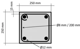
20 MPa with a maximum aggregate size of 20 mm. The reinforcement consists of 4 longitudinal deformed bars of 12 mm diameter and stirrups of 8 mm diameter spaced every 200 mm, as shown in Fig.7.
The test campaign has been conducted taking into account safety issues due to the elevated levels of energy stored and quickly released during the experiments. For this reason and taking into account the high complexity of the equipment under operation, the energy involved during the experiments has been increased gradually. The set-up is also covered by a safety box (a mixed aluminium and polycarbonate panel structure) that protects the operators conducting the experiment from accidental debris.
Figure 8. Schematic top view of the geometry of the experiments.
do not have a high scientific value, they have allowed a better knowledge of the equipment performance and of the test evolution. The tests have been performed by storing energy only in the actuator spring and a maximum velocity of about 12 m/s has been reached. Following this test, the column has been judged to be overly damaged to continue with additional tests on it.
On the contrary, the last test presented in this paper can be considered to have a greater scientific value even though a series of experimental setbacks have occurred (the acquisition of piezoelectric sensors failed for a bug of the transient recorder). The test has been performed by employing the energy of the springs and of pressurized nitrogen in order to increase the impact velocity of the mass (about 17 m/s). The beam has been seriously damaged and patterns of a shear failure mode have appeared (also typical of blast load failure).
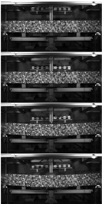
A first analysis of the recorded data has been made and some results in the form of images and diagrams are presented in the following. Figure 8 provides a general picture of the geometry of the impactor, the beam specimen and its supports, which helps in understanding the diagrams produced below for each one of the tests. Figure 9 presents a selection of representative frames of the high-speed photo-sequence captured during the last test with the high speed camera placed perpendicularly above the specimen.
The impacting mass hits normally the RC beam (frames 1 and 2) and forces it to bend, as shown in the frames 3 and 4. For the specific test, due the non-symmetric behaviour of the specimen, the beam mainly fails in the left part as underlined by the rotation of the impacting mass (frame 4). In addition to the qualitative information that can be deduced by the high speed camera photo sequence (type of damage, possible rebounds, impact misalignments, etc.), special analyses have been employed for these optical data to obtain quantitative measures.
Specifically, two different algorithms have been applied:
• a fast tracking algorithm [3] that returns an accurate measure (in the order of 0.01 mm) of the position of
Figure 9. High speed photo sequence; time = 14 ms, 24 ms, 34 ms and 40 ms.
Figure 10. Beam target displacements (along impact direction).
the particular Gaussian grayscale targets applied to the column and to the impacting mass (Fig.9);
• a full-field technique, the so called optical flow algorithm [4], that returns the displacement of each image pixel (with less precision compared with the previous algorithm), useful to study the evolution of the fracture paths during the test.
Figure 11. Mass load cell signals.
been presented. The impact starts approximatively at 22 ms and the maximum deflection occurs at 40 ms as underlined by the graph (the contact between the mass and the specimen lasts less than 8 ms). Obviously the curves that present the greater deflections are related to targets located in the central part of the column. After 40 ms the elastic unloading of the damaged column starts, which causes the rebound of the specimen in the direction opposite to the impact. At 100 ms the bending oscillations due to the impact are substantially finished and the displacements of the targets are representative of the damaged shape of the beam. A permanent deflection of about 50 mm has been reached in the central part of the beam.
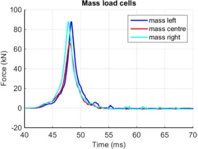
For what concerns the piezoelectric sensors placed on the impacting mass, Fig.11 shows the signals recorded during the last experiment conducted on the first beam (the specimen was already damaged by previous experiments performed at low impact velocities). The direct measures of the impacting forces are totally noiseless and no ringing phenomena of the transducers occur in the duration of the test. In addition it is possible to observe that the force transmitted by the central plate is lower compared with those of the two lateral plates due to the pre-existing damage in the specimen. In any case the peak load and the duration of the pulses generated by the equipment are comparable with the experimental data obtained from experiments conducted with explosives.
Figure 12 shows the impulses related to Fig. 11. As expected, the signal derived by the central plate is lower compared with the two lateral ones.
4. Numerical simulations
Finite element analysis has been performed, in order to verify the experimental results and to ameliorate the final configuration of the apparatus. The geometrical model presented in Fig. 8 has been discretised, as depicted in Fig. 13, with finite elements via the CAST3M code [5]. The numerical calculations have been performed with the EUROPLEXUS explicit finite element code [6]. Hexahedral solid elements with eight nodes, one integration point and linear displacement interpolation have overall been preferred.
Figure 12. Impulses applied by three plates.
Figure 13. Finite element model of the impacting mass.
Different element types and sizes are employed in the representation of the impacting mass. For the massive steel part a relatively coarse mesh has been used since it will not undergo high strains (cubic edge size 20 mm). For the load cells, the aluminium plates and the polyurethane foam finer meshes have been used with an average cubic edge of 5 mm.
The concrete beam has been discretised with cubic finite elements of 20 mm edge size, while the reinforce-ment has been modelled with 1-D bar elereinforce-ments. The bonding between the concrete and the reinforcement has been modelled with a procedure that links the displacement of the nodes belonging to the continuum-like elements of concrete, with those of the bar-like elements of steel.
Figure 14. Stress-strain curve for the polyurethane foam.
Figure 15. Velocity of the impactor.
of the structure, while Fig. 14 presents the stress-strain curve for the polyurethane foam (both experimental and numerical).
The impactor is moving with an initial velocity until it collides with the specimen. The pinball method [8,9] has been used for the contact between the impacting mass and the specimen. The RC beam has been blocked in the vertical direction for all the points lying on the support lines.
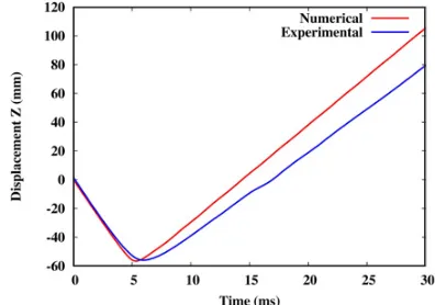
Figures15and16present the comparison between the experimental and numerical results concerning the velocity and the displacement of the impactor in one of the initial tests. As seen, there is a relatively good agreement between the two approaches.
Figure 16. Displacement of the impactor.
5. Conclusions
Towards developing a blast simulator, a fast, spring-gas driven actuator and an innovative impactor have been constructed. Their performance has been assessed through appropriately instrumented tests. The results obtained from these tests demonstrate that the developed blast actuator is capable of reproducing through impact the required pressure levels to bring real structural members (reinforced concrete beams) to failure. Numerical simulations are also conducted, successfully modelling the experiments and pointing to improvements in the performance of the apparatus.
References
[1] G.A. Hegemier, F. Seible, T. Rodriguez-Nikl, K. Arnett, Blast Mitigation of Critical Infrastructure Components and Systems, FIB Proceedings of the 2nd International Congress, June 5–8 2006, Naples, Italy, paper ID: 11–2
[2] M. Peroni, G. Solomos, B. Viaccoz, Blast Simulator project: Performance assessment and preliminary tests, Report JRC 86864
[3] P. Caperan, M. Poljansek, E. Gutierrez, S. Primi, C. Paulotto, Comp. Struct. 94, 2012
[4] C. Zach, T. Pock, H. Bischof, A Duality Based Approach for Realtime TV-L1 Optical Flow, Pattern
Recognition, Springer, 2007 [5] http://www-cast3m.cea.fr
[6] EUROPLEXUS User’s manual, 2015; http:// www-epx.cea.fr
[7] S. Kolling. P.A. Du Bois. D.J. Benson and W.W. Feng. Comp. Mech., 40:885–899, 2007
[8] T. Belytschko, M.O. Neal, Int. J. Num. Meth. Engng., 31:547–572, 1991