IJEDR1603132
International Journal of Engineering Development and Research (www.ijedr.org)806
Performance Evaluation of Voltage Profile Stability
Under Dual Side Fault Condition Using Static var
Compensator
1Mohammad Avaish Khan, 2Mr. Rajkumar Jhapte, 3Mr. Mahesh Singh 1PG Scholar, 2Sr. Assistant Professor, 3Sr. Assistant Professor
1Department of Electrical Engineering
1Faculty of Engineering and Technology, SSGI (SSTC), Bhilai, India
________________________________________________________________________________________________________
Abstract-A Static Var Compensator (SVC) is basically a shunt FACTS device, most often whose output is attuned to exchange capacitive or inductive current to the system. The voltage profile improvement is a process of improvement reactive power transfer or to provide better and stable voltage during transmission of power through transmission lines. This paper basically presents the performance evaluation of conventional PI controller based voltage regulator SVC system for voltage profile improvement.
Index terms:Voltage Stability,Three Phase Transmission system, Voltage Regulation, PI controller, SVC.
______________________________________________________________________________________
1. Introduction
The concept of Flexible AC transmission system has been proposed in 1995, which is called FACTs. The basic idea of FACTs is install the power electronic devices at the high-voltage side of the power grid to make the whole system by electronic means controllable. The advances achieve in high power semiconductor devices and control technology makes the basis of the development of FACTs. The FACTs devices are able to provide active and reactive power to the power grid quickly. The power reimbursement achieved by FACTs devices could adjust the voltage of the whole system and the power flow might be adequately controlled. Generally, the FACTs devices and technology could be divided into two generations:
Figure1.The category of FACTs devices
I. Dynamic devices and fixed capacitance devices. This is the first generation of the FACTs devices. In this period, the usual devices are including tap changing and phase changing transformer, synchronous generator and series capacitors. Apart from the series capacitors, which could also be called capacitor bank, others are dynamic devices. These devices are primarily controlled at the generation side of the power grid and the cost is typically expensive. When talk about the series capacitors, the disadvantage of this device could hardly be omitted. Since the device is made up of many fixed-capacitance capacitors, it could hardly be controlled to provide the real not-fixed capacitance to the grid.
II. Static state compensator. This is the second generation of the FACTs devices. It could be classified into two categories: thyristor base devices and fully-controlled devices base compensator. The thyristor is called half-controlled device, as it can only be controlled to switch on but not to cut off. Static Var Compensator (SVC) and Thyristor-Controlled Series Capacitor (TCSC) are incorporated in this category. The fully controlled devices mainly involve GTO etc. The Static Compensator
© 2016 IJEDR | Volume 4, Issue 3 | ISSN: 2321-9939
IJEDR1603132
International Journal of Engineering Development and Research (www.ijedr.org)807
(STATCOM), Solid State Series Compensator (SSSC), Unified Power Flow Controller (UPFC) and HVDC-Voltage Source Converter (HVDC-VSC) are incorporated in this group.This paper focus on the performance evaluation of conventional PI controller based voltage regulator for voltage profile improvement.
2. Basic operation of SVC
The static var compensator adjusts the voltage by controlling the reactive power amount absorbed from or injected into the power system. For instance, it generates reactive power by switching capacitor banks when the system voltage is low down or loads are inductive. Accordingly, the lagging load demanded the reactive power is supplied by the SVC relieve the distributing lines from delivering it. As a result, the voltage drops reduce and the voltage at the load terminals shall get better.
Similarly, the static var compensator absorbs reactive power when the system voltage is high or loads are capacitive. In this case, the SVC uses the reactors to consume the VARs from the system, thereby lower the system voltage.
2.1 Design and Configurations of SVC
There are three common configurations of static var compensators and each will be described below.
(i). Thyristor-controlled Reactors with Fixed Capacitors (TCR/FC)
This SVC design having two parallel branches connected on the secondary side of a coupling transformer. One of the branches is uses reactors that are controlled by AC thyristor switches. Additionally, the reactors are connected in delta for three-phase applications. The other branch could either be fixed capacitor banks or shunt filters.
The discrepancy of reactive power is achieved by controlling the thyristor’s firing instants and, accordingly, the current that flows by the reactance.
Figure 2 Thyrsitor-controlled Reactors with Fixed Capacitors (or Shunt Filters)
IJEDR1603132
International Journal of Engineering Development and Research (www.ijedr.org)808
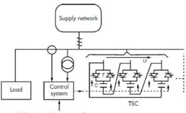
Figure 3 Thyristor-switched Capacitors (TSC)In this type of static var compensator device, the capacitor banks are linked phase-to-phase, with each section switched by thyristors. Thus, a distinct variation of the reactive power can be attaining but not a continuous alteration similar to that of a TCR. On the other hand, by given that a suitably large number of small sections, the required resolution of reactive power alteration for a single step can be achieved. Synchronization of switching and initial pre-charging of the capacitors limits the transients usually linked with capacitor switching. Generally, the reaction time for symmetrical operation does not exceed 20 ms.
(iii). Thyristor-controlled Reactors and Thyristor switched capacitors (TCR/TSC)
Fundamentally, this is the grouping of TCR and TSC. In this configuration, the control of the static var compensator is depends on measuring the reactive component of load current at the instantaneous of voltage zero. Subsequently, the measured current is used to obtain the firing angle so that the SVC absorbs or injects the amount of reactive power requisite for compensation.
However, there is a time interval between the instant of measuring the reactive component (in one half-cycle) and the firing instant (the next half-cycle). This natural delay of its operation mode is one of its major limitations.
3. Methodology
3.1 AC lines Voltage Regulation using Conventional Static var compensator
© 2016 IJEDR | Volume 4, Issue 3 | ISSN: 2321-9939
IJEDR1603132
International Journal of Engineering Development and Research (www.ijedr.org)809
Figure 4. Single line voltage regulation using SVC.The control system of conventional SVC consists of:
A measurement system determining the positive-sequence voltage to be controlled. A Fourier-based dimension system
using an average of one-cycle running is used.
A voltage regulator that uses the voltage error (difference between the measured voltage Vm and the reference voltage
Vref) to find out the SVC susceptance BSVC needed to keep the system voltage constant.
A distribution unit that decides the TSCs (and eventually TSRs) that must be switched in and out, and computes the firing angle α of TCRs.
A synchronizing system using a phase-locked loop (PLL) synchronized on the secondary voltages and a pulse generator that send suitable pulses to the thyristors. SVC with the voltage regulation unit accepts measured voltage from the line Vm and reference voltage Vref to generate the controlled SVC susceptance BSVC needed to keep the line voltage constant.
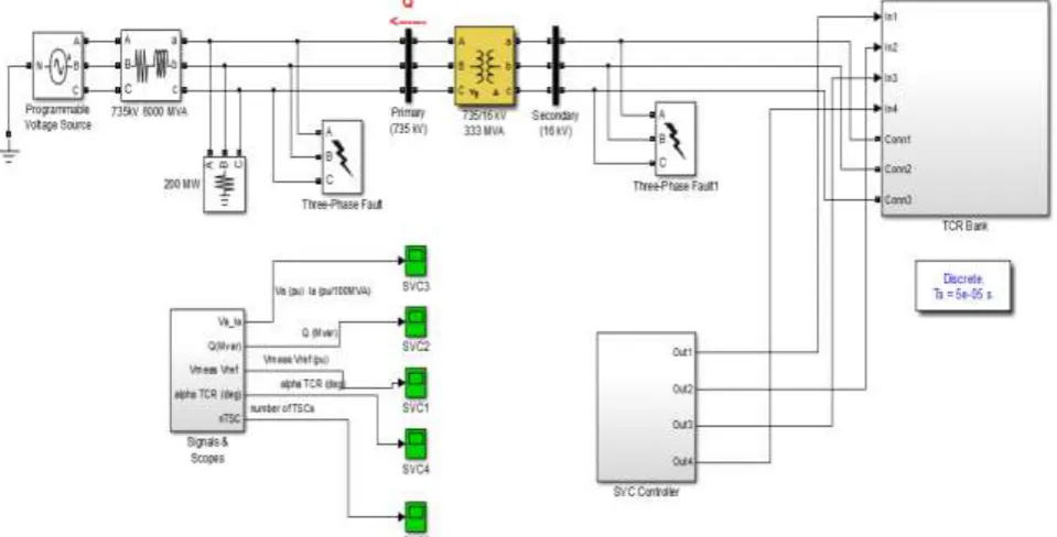
Figure 5. Simulation Diagram for SVC Regulated three phase system
IJEDR1603132
International Journal of Engineering Development and Research (www.ijedr.org)810
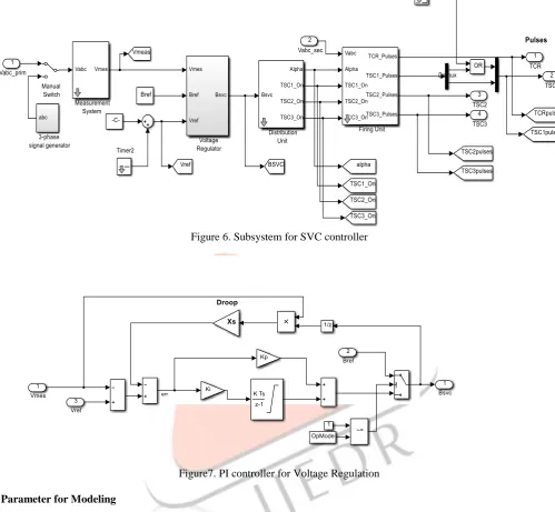
Figure 6. Subsystem for SVC controllerFigure7. PI controller for Voltage Regulation
4. Parameter for Modeling
Three Phase Programmable Voltage Source
This block implements a three-phase zero-impedance voltage source. The common node (neutral) of the three sources is accessible via input 1 (N) of the block.
Amplitude (Vrms Ph-Ph) – 735x103, Phase (deg.) – 0, Freq. (Hz) – 60
Three Phase Series RL Branch
Implements a three-phase series RL branch having R = 9.0038 (ohm), L = 0.23895 (h).
Three Phase Series RLC Load- VRMS- 735x103, Power rating P= 200MW
Ratings of TCR and TSC
TCR= 109 Mvar TSC1= TSC2 = TSC3= 94 Mvar
4. Performance Evaluation of PI controller based voltage regulator for voltage profile Improvement
© 2016 IJEDR | Volume 4, Issue 3 | ISSN: 2321-9939
IJEDR1603132
International Journal of Engineering Development and Research (www.ijedr.org)811
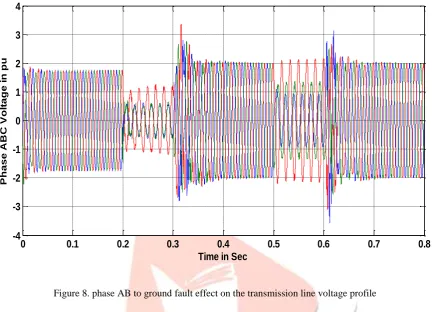
The first case study is performed by taking phase AB to ground fault for both the primary and secondary side. The three phase voltage waveform obtained for this case is shown in figure (8).Figure 8. phase AB to ground fault effect on the transmission line voltage profile
The above figure clearly indicates that the there are two fault conditions on phase A and phase B on two different time spans. The first fault is occurred here for .1 sec fron t = 0.2 sec to t = 0.3 sec while the second fault is occurred for again .1 sec from t = .5 sec to t = .6sec.
Now the results obtained after restoration of the means voltage for the conventional SVC based system is shown in figure (9).
From the above figure it is clear that, during the fault timing the means voltage dropped to very low values but after the clearance of fault the conventional SVC settles the voltage within the tolerance range of .1 pu, which indicates the 90 percent efficiency of the conventional SVC to recover and provide voltage stability.
0 0.1 0.2 0.3 0.4 0.5 0.6 0.7 0.8
-4 -3 -2 -1 0 1 2 3 4
Time in Sec
P
h
a
s
e
A
B
C
V
o
lt
a
g
e
i
n
p
IJEDR1603132
International Journal of Engineering Development and Research (www.ijedr.org)812
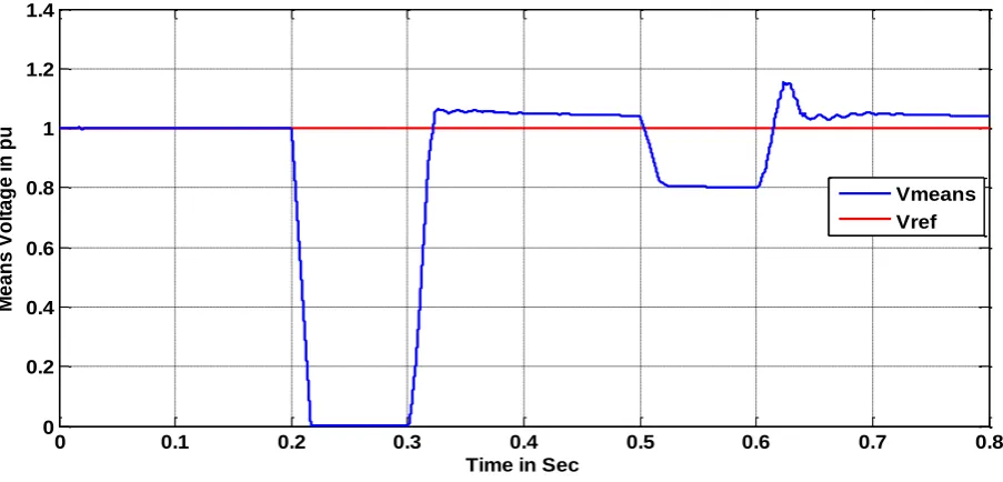
Figure 9. The line voltage regulation response of SVC systemThe second case study is performed by taking phase ABC to ground fault for both primary and secondary side. The three phase voltage waveform obtained for this case is shown in figure (10).
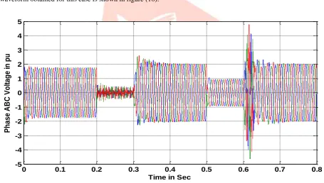
Figure 10. Phase ABC to ground fault effect on the transmission line voltage profile
The above figure shows that the again there are two fault conditions on phase A, phase B and phase C on two different time spans. The first fault is occurred here for .1 sec fron t = 0.2 sec to t = 0.3 sec while the second fault is occurred for again .1 sec from t = .5 sec to t = .6sec.
Now the results obtained after restoration of the means voltage for the conventional SVC based system is shown in figure (11).
0 0.1 0.2 0.3 0.4 0.5 0.6 0.7 0.8
0.2 0.3 0.4 0.5 0.6 0.7 0.8 0.9 1 1.1 1.2 M e a n s V o lt a g e i n p u
Time in Sec
Vmeans Vref
0 0.1 0.2 0.3 0.4 0.5 0.6 0.7 0.8
-5 -4 -3 -2 -1 0 1 2 3 4 5
P
h
a
s
e
A
B
C
V
o
lt
a
g
e
in
p
u
© 2016 IJEDR | Volume 4, Issue 3 | ISSN: 2321-9939
IJEDR1603132
International Journal of Engineering Development and Research (www.ijedr.org)813
Figure 11 The line voltage regulation response of SVC system5. Conclusions
In this paper a complete performance evaluation of conventional PI controller based voltage regulation for analyzing the voltage profile improvement have been successfully implemented and simulated in MATLAB 2012 (b) Simulink. It is observable from the results obtained that conventional PI controller based voltage regulation SVC system can able to provide stable voltage in the transmission lines up to a good extent but not able to control the reactive power completely in transient part where the line voltage fluctuates.
In addition to this the obtained results also indicates that, the conventional PI controller based voltage regulation SVC system is good enough to maintain constant voltage in steady state part after fluctuations occurred. Hence this system is able to provide good power stabilization in steady state part during power transmission.
To develop more fine results, the presented work of this paper can be further extend with the modification of the control mechanism of SVC voltage regulation system by using advance control structures like fuzzy controller, neural network controllers and adaptive neural fuzzy controllers to replace conventional PI controllers used in the TCSC.
6. Reference
[1]
A. Gupta and P. R. Sharma, "Fuzzy based Svc auxiliary controller for damping low frequency oscillations in a power system," Confluence 2013: The Next Generation Information Technology Summit (4th International Conference), Noida, 2013, pp. 87-91.[2]
A. M. Hemeida, S. Alkhalaf and O. Alfarraj, "Control quality assessment of fuzzy logic controller based static VAR compensator (SVC)," SAI Intelligent Systems Conference (IntelliSys), 2015, London, 2015, pp. 507-517.[3]
A. C. M. Valle, A. O. Borges, G. C. Guimaraes and H. R. Azevedo, "Fuzzy logic controller simulating an SVC device in power system transient stability analysis," Power Tech Proceedings, 2001 IEEE Porto, Porto, 2001, pp. 4 pp. vol.4[4]
N. A. Arzeha, M. W. Mustafa and R. Mohamad Idris, "Fuzzy-based Static VAR Compensator controller for damping power system disturbances," Power Engineering and Optimization Conference (PEDCO) Melaka, Malaysia, 2012 IeeeInternational, Melaka, 2012, pp. 538-542
[5]
S. Khanmohammadi, M. T. Hagh and M. Abapour, "Fuzzy logic based SVC for reactive power compensation and power factor correction," 2007 International Power Engineering Conference (IPEC 2007), Singapore, 2007, pp. 1241-1246.[6]
A. Kazemi and M. V. Sohrforouzani, "Power system damping using fuzzy controlled FACTS devices," Power SystemTechnology, 2004. PowerCon 2004. 2004 International Conference on, 2004, pp. 1623-1628 Vol.2
[7]
T. Abdelazim and O. P. Malik, "Intelligent SVC control for transient stability enhancement," IEEE Power EngineeringSociety General Meeting, 2005, 2005, pp. 1701-1707 Vol. 2.
[8]
T. Abdelazim and O. P. Malik, "Intelligent SVC control for transient stability enhancement," IEEE Power EngineeringSociety General Meeting, 2005, 2005, pp. 1701-1707 Vol. 2.
[9]
S. Khan, R. Meena and S. Bhowmick, "Small signal stability improvement of a single machine infinite bus system using SVC," 2015 Annual IEEE India Conference (INDICON), New Delhi, 2015, pp. 1-5.[10]
A. Gelen and T. Yalcinoz, "The behaviour of TSR-based SVC and TCR-based SVC installed in an infinite bus system,"Electrical and Electronics Engineers in Israel, 2008. IEEEI 2008. IEEE 25th Convention of, Eilat, 2008, pp. 120-124.
[11]
J. Zhu, D. Hwang and A. Sadjadpour, "Loss reduction from use of new SVC model," Power and Energy Society GeneralMeeting - Conversion and Delivery of Electrical Energy in the 21st Century, 2008 IEEE, Pittsburgh, PA, 2008, pp. 1-7.
0 0.1 0.2 0.3 0.4 0.5 0.6 0.7 0.8
0 0.2 0.4 0.6 0.8 1 1.2 1.4 M e a n s V o lt a g e i n p u
Time in Sec
IJEDR1603132
International Journal of Engineering Development and Research (www.ijedr.org)814
[12]
Peiyuan Chen, Zhe Chen and B. Bak-Jensen, "Comparison of steady-state SVC models in load flow calculations,"Universities Power Engineering Conference, 2008. UPEC 2008. 43rd International, Padova, 2008, pp. 1-5.
[13]
R. Grunbaum, M. Halonen and G. Stromberg, "SVC for 69 kV direct grid connection," 2008 IEEE/PES Transmissionand Distribution Conference and Exposition, Chicago, IL, 2008, pp. 1-7.