IJEDR1504019
International Journal of Engineering Development and Research (www.ijedr.org)1
Modelling of PLL based Frequency Multiplier
System using VHDL - AMS – A Hardware
Descriptive Language
1
Meet Poladia,
2Dheeraj Pandey
1, 2 PG Students
1Department of Electronics and Telecommunication Engineering, 1Sardar Patel Institute of Technology, Mumbai, India
________________________________________________________________________________________________________
Abstract - This paper provides an overview of the VHDLAMS hardware description language for analog and mixed-signal applications like the phase locked loop system which is designed by describing the major elements or components of the system with the help of this hardware descriptive language and illustrating it using Hamster which is a simulation software for VHDL and Verilog Descriptive Language.
Index Terms – PLL, VHDL – AMS, Verilog AMS, analog simulations, mixed signal simulations.
________________________________________________________________________________________________________
I.INTRODUCTION
Hardware description languages (HDL’s) are programming languages designed for describing the behavior of physical devices and processes, a task commonly called modelling. Models written in an HDL are used as input to a suitable simulator to analyze the behavior of the devices. HDL’s have been used since the 1960’s to model and simulate applications as diverse as digital and analog electronic systems, fluid concentrations in chemical processes, and parachute jumps.
Modern HDL’s support the description of both behavior and structure. The structural mechanisms of an HDL allow a user to compose the model of a complete system from reusable model components stored in a library. Stored components are assembled into a design hierarchy that often closely resembles the decomposition of the system into subsystems and sub subsystems. The behavioral mechanisms of an HDL allow a user to express the operation of a subsystem at various levels of abstraction: very detailed, highly abstract, or anything in between. The designer can proceed using a top-down methodology, first performing conceptual studies using less detailed models, and then continually refining the design until each subsystem has been completed in sufficient detail for implementation. Top-down design and indefinite extensibility using stored components are the major advantages of an HDL based design methodology over traditional approaches.
In this contribution, we give an overview of VHDL-AMS, a new hardware description language for analog, digital, and mixed-signal applications. VHDL-AMS is an informal name for the combination of two IEEE standards: VHDL 1076-1993 and VHDL 1076.1-1999. In Section II introduces the elements of the language, focusing on the static semantics of the extensions introduced by IEEE Std. 1076.1-1999. Each language element is illustrated by examples. Finally, Section IV describes the modelling of the Phase Locked Loop System with its simulation results.
II.OVERVIEW OF VHDLAMSMODELS
A VHDL-AMS model consists of an entity and one or more architectures. The entity specifies the interface of the model to the outside world. It includes the description of the ports of the model (the points that can be connected to other models) and the definition of its generic parameters. The architecture contains the implementation of the model. It may be coded using a structural style of description, a behavioral style, or a style combining structural, and behavioral elements. A structural description is a net list it is a hierarchical decomposition of the model into appropriately connected instances of other models. A behavioral description consists of concurrent statements to describe event-driven behavior and simultaneous statements to describe continuous behavior. Concurrent statements include the concurrent signal assignment for data flow modeling and the process statement for more general event-driven modeling.
When a VHDL-AMS model is instantiated in a structural description, the designer can specify which of several architectures to use for each instance. Alternatively, the decision can be postponed until immediately prior to the simulation. This allows for an easy and flexible reconfiguration of the model. For example, in top-down design, one architecture can describe a subsystem behaviorally with little detail, while another can add parasitic and a third can decompose the subsystem into lower level components.
Quantities
IJEDR1504019
International Journal of Engineering Development and Research (www.ijedr.org)2
VHDL-AMS introduces a new class of objects, the quantity, to represent the unknowns in the DAE’s. Quantities can be scalar or composite (arrays and records), but must have scalar sub elements of a floating-point type. A quantity object can appear anywhere a value of the type is allowed, in particular in an expression. In the remainder of this section, we describe the characteristics of scalar quantities. The characteristics of a composite quantity are simply the aggregation of the characteristics of its scalar sub elements. The behavior of each scalar sub element is independent of the others.Quantities can be declared anywhere a signal can be declared except in a VHDL package. The following statement declares three quantities q1, q2, and q3 of type REAL:
quantity q1,q2,q3: REAL
where bold text indicates reserved words and upper-case text indicates predefined concepts.
Simultaneous Statement
Simultaneous statements are a new class of statements in VHDL-AMS for notating differential and algebraic equations. Simultaneous statements contain ordinary VHDL expressions that can be evaluated in the ordinary way. Simultaneous statements can appear anywhere a concurrent signal assignment is allowed. The basic form is the simple simultaneous statement, which has the following syntax:
[label :] expression = expression where the square brackets indicate that this part of the statement is optional.
Several additional forms of the simultaneous statement have been defined. The simultaneous case statement and simultaneous if statement are analogous to their sequential counterparts and allow the description of piecewise defined behavior. Each contains an arbitrary list of simultaneous statements in its statement parts, including nested simultaneous case and if statements. The analog solver considers only the simultaneous statements selected by the case expressions and chosen by the conditional expressions. The simultaneous procedural statement is merely a way to rewrite the function body f in the simultaneous statement f(q,x) = q “in line,” where q is a collection of quantities and x is an arbitrary collection of other objects.
Modelling of a Resistor using VHDL AMS
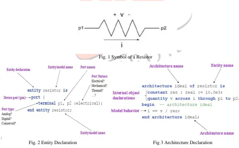
In VHDL AMS, the model comprises of two sections that is the entity and the architecture. In this section we will see the modelling of a passive resistor using the VHDL AMS. Fig. 1 shows basic symbol of a resistor where p1 and p2 are two end points and as we all know that the resistor works on the principal of ohms law i.e V = I*R. Fig 2 and 3 show the entity and architecture declarations of a resistor. In the same manner all the other components can be modelled using both VHDL AMS or Verilog AMS HDL’s.
Fig. 1 Symbol of a Resistor
Kk Aca D Sd D S
Fig. 2 Entity Declaration Fig 3 Architecture Declaration
III.MODELLING OF SMPS
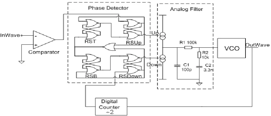
A frequency multiplier is an electronic circuit that generates an output signal whose output frequency is a harmonic (multiple) of its input frequency. Frequency multipliers consist of a nonlinear circuit that distorts the input signal and consequently generates harmonics of the input signal. A subsequent band pass filter selects the desired harmonic frequency and removes the unwanted fundamental and other harmonics from the output.
IJEDR1504019
International Journal of Engineering Development and Research (www.ijedr.org)3
phase detector and analogue filter architectures are structures that use standard library components. The VCO architecture is behavioural and uses the phase integrator described in the example model of VCO.Fig. 4 Simulation Model of a PLL based Frequency Multipier.
Modelling of an Comparator
library IEEE; use IEEE.math_real.all; use IEEE.electrical_systems.all;
use IEEE.std_logic_1164.all;
-- Behavioral model of the comparator entity Comparator is
generic( Vthreshold: voltage := 0.0); -- [V] comparator threshold level
port(terminal PveT,NveT: electrical; -- analog input pins
signal SOut: out std_logic -- digital output );
end entity Comparator ;
architecture Behavior of Comparator is quantity DeltaV across PveT to NveT; -- differential
input voltage begin
-- the architecture consists of one concurrent signal assignment statement
Sout <='1' when DeltaV'above(Vthreshold) -- trigger event when V+>V- +Vth
else '0' ; -- trigger event when V+<V- -Vth end architecture Behavior;
Modelling of a RS Flip Flop
library IEEE;
use IEEE.std_logic_1164.all;
-- digital behavioral model of RS flip-flop entity RSFF is
generic (DelayQ, DelayQB: TIME := 1 ns); port ( R,S: in std_logic;
Q,QB: out std_logic); end entity RSFF;
architecture Behavior of RSFF is signal Qin: std_logic:='0'; signal QBin: std_logic:='0';
begin
Qin<= '0' when R='1'and S='1' else '0' when R='1'and S='0' else '1' when R='0'and S='1' else
not QBin after 1ns; QBin<= '0' when R='1' and S='1' else
'1' when R='1' and S='0' else '0' when R='0' and S='1' else
not Qin after 1ns;
Q<=Qin after 1 ns; QB<=QBin after 1 ns; end architecture Behavior; -- RSFF
Modelling of the VCO block
library IEEE; use IEEE.math_real.all; use IEEE.electrical_systems.all;
entity VCO is generic(
fc: real := 1.0E6; -- VCO frequency at Vc df: real := 0.5E6; -- [Hz/V], frequency
Modelling of the Counter
library IEEE;
use IEEE.std_logic_1164.all;
-- a behavioral model of the digital counter entity Counter is
generic (Count: positive := 2; -- divide-by-two by default
IJEDR1504019
International Journal of Engineering Development and Research (www.ijedr.org)4
characteristic slope
Vc: voltage := 0.0 -- centre frequency input voltage
);
port(quantity Vin: in voltage;
terminal OutTerminal,ground: electrical); end entity VCO;
architecture PhaseIntegrator of VCO is constant TwoPi: real := 6.283118530718; -- 2pi
-- Phase is a free quantity: quantity Phase : real;
-- define a branch for the output voltage source quantity Vout across Iout through OutTerminal to
ground;
begin
if domain = quiescent_domain use Phase == 0.0;
elsif Phase'above(TwoPi) use Phase == 0.0;
else
Phase'dot == TwoPi*realmax(0.1E6, fc+(Vin-Vc)*df);
end use;
break on Phase'above(TwoPi);
-- output voltage source equation Vout == 2.5*(1.0+sin(Phase));
end architecture PhaseIntegrator;
);
port (Input : in std_logic; -- input and output pins Output : out std_logic);
end entity Counter;
architecture Behavioral of Counter is begin
-- declare a process with a variable to memorise counter state
process(Input) is -- process is triggered by an input event
variable CurrentCount : natural := 0; -- count memory
begin
if Input='1' then -- a rising edge occured CurrentCount := (CurrentCount+1) mod Count;
-- flip the output every Count/2 pulses if CurrentCount < Count / 2 then
Output <= '0' after Delay; else Output <= '1' after Delay;
end if;
end if; end process;
end architecture Behavioral; -- Counter
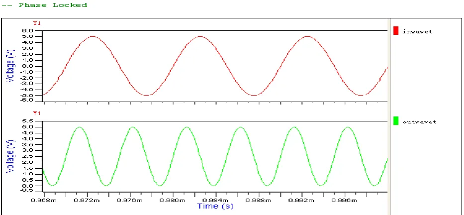
Above we have shown modelling of various components used the the circuit diagram of the PLL based frequency multiplier model. After simulation in Hamster software we get the desired result which is shown below:-
IJEDR1504019
International Journal of Engineering Development and Research (www.ijedr.org)5
IV.CONCLUSION
We have given an overview of VHDL-AMS, a hardware description language for analog, digital, and mixed-signal applications. We have focused on the main aspects of the language and illustrated the introduction of the language concepts by example of the mixed signal frequency multiplier system based on PLL and giving the modelling codes in VHDL AMS language for some of the components used in PLL. VHDL-AMS includes much more, and the interested reader is encouraged to explore the language by studying the language reference manual [4] and other available literature.
V.ACKNOWLEDGMENT
The authors of this paper take this opportunity to thank all the concerned who helped us in our research. We would like to acknowledge our Institute, Department of Electronics and Telecommunication Engineering for their constant motivation and support and helping us all to frame the issues and giving us proper guidance.
At last, we also thank all our colleagues who assisted and backed us during our research.
REFERENCES
[1] VHDL Language Reference Manual, IEEE Standard 1076-1993.
[2] Standard Description Language Based on the Verilog(TM) Hardware Description Language, IEEE Standard 1364-1995. [3] J. C. Strauss et al., “The SCI continuous system simulation language (CSSL),” Simulation, pp. 281–303, Dec. 1967. [4] Definition of Analog and Mixed Signal Extensions to IEEE Standard VHDL, IEEE Standard 1076.1-1999.
[5] 1076.1 Design Objective Document V 2.3 (1995). [Online]. Available HTTP: http://vhdl.org/vi/analog [6] 1076.1 Design Objective Rationale V 1.2 (1995). [Online]. Available HTTP: http://vhdl.org/vi/analog