Integrated Simulation Design Challenges to Support
TPS Repair Operations
Leslie J. Quiocho
∗and Edwin Z. Crues
† NASA Johnson Space Center, Houston, Texas, 77546, USAAn Huynh
‡and Hung T. Nguyen
§Jacobs Sverdrup ESCG, Houston, Texas, 77058, USA
John R. MacLean
¶METECS, Houston, Texas, 77059, USA
During the Orbiter Repair Maneuver (ORM) contingency operations planned for Re-turn to Flight (RTF), the Shuttle Remote Manipulator System (SRMS) must grapple the International Space Station (ISS), undock the Orbiter, maneuver it through a long du-ration trajectory, and orient it such that an EVA crew person poised at the end of the Space Station Remote Manipulator System (SSRMS) can facilitate the repair of the Ther-mal Protection System (TPS). Once repair has been completed and confirmed, then the SRMS proceeds back through the trajectory to dock the Orbiter to the Orbiter Docking System. In order to support analysis of the complex dynamic interactions of the integrated system formed by the Orbiter, ISS, SRMS, and SSRMS during the ORM, simulation tools used for previous ‘nominal’ mission support required substantial enhancements. These up-grades were necessary to provide analysts with the capabilities needed to study integrated system performance. This paper discusses the simulation design challenges encountered while developing simulation capabilities to mirror the ORM operations. The paper also describes the incremental build approach that was utilized, starting with the subsystem simulation elements and integration into increasingly more complex simulations until the resulting ORM work site dynamics simulation had been assembled. Furthermore, the pa-per presents an overall integrated simulation V&V methodology based upon a subsystem level testing, integrated comparisons, and phased checkout.
I.
Introduction
Prevalent throughout the ORM operation is a dynamically varying topology. In other words, the ORM starts with the SRMS grappled to the mated Shuttle/ISS stack (closed loop topology), moves to an open loop chain topology consisting of the Shuttle, SRMS, and ISS, and then, at the repair configuration, extends the chain topology to one consisting of the Shuttle, SRMS, ISS, and SSRMS/EVA crew person. The resulting long dynamics chain of vehicles and manipulators may exhibit significant motion between the Shuttle work site and the EVA crew person due to the system flexibility throughout the topology (particularly within the SRMS/SSRMS joints and links). Since the attachment points of both manipulators span the flexible structure of the ISS, simulation analysis may also need to take that into consideration. Moreover, due to the
∗AST, Robotics Specialist, Mail Code ER7, Phone: 281-483-8633, Email: [email protected], Associate Member. †AST, Robotics Specialist, Mail Code ER7, Phone: 281-483-2902, Email: [email protected], Senior Member. ‡Dynamics Specialist, Mail Code JE07, Phone: 281-483-2067, Email: [email protected].
§Systems Simulation Engineer, Mail Code JE07, Phone: 281-483-8180, Email:[email protected]. ¶Chief Robotics Engineer, Phone: 832-476-8651, Email:[email protected].
1 of 8
American Institute of Aeronautics and Astronautics AIAA Guidance, Navigation, and Control Conference and Exhibit
15 - 18 August 2005, San Francisco, California
AIAA 2005-5988
lengthy time duration associated with the maneuver and repair, orbital effects become a factor and require the ISS vehicle control system to maintain active attitude control.
Several facets of the ORM operation make the associated analytical efforts different from previous mission support, including: (1) the magnitude of the SRMS handled payload (i.e., Orbiter weight class), (2) the orbital effects induced on the integrated system consisting of the large Shuttle and ISS masses connected by a light flexible SRMS, (3) long duration environmental consequences due to the lengthy operational times associated with the maneuver and repair of the TPS, (4) active attitude control (as opposed to free drift) interacting with the SRMS and SSRMS manipulators (also due to the length of the maneuver and repair), (5) relative dynamics between the EVA crew person and the work site influenced by the extended flexible topology.
In order to meet these analysis challenges, an ORM simulation architecture was developed leveraging upon numerous pre-existing simulation elements to analyze the various subsystems individually. For example, core manipulator subsystem simulations for both the SRMS and SSRMS were originally combined to provide the dual-arm dynamics topology simulation (in the absence of orbital dynamics and vehicle control). This capability was later merged with the simulation used to analyze SRMS loading with a heavy payload in the orbital environment and an active payload control system (in this case, the ISS Attitude Control System (ACS)), configured for the ORM. The resulting work site dynamics simulation, based off of the modified ORM simulation, provided the extended topological chain of vehicles and manipulators, while taking into account the orbital effects of both the Shuttle and ISS (as well as its ACS).
Verification and validation (V&V) of these integrated simulations became a challenge in itself. A sys-tematic approach was developed such that integration simulation results could be tested against previous constituent simulations upon which these simulations were built. General V&V categories included: (1) orbital state propagation, (2), stand-alone SRMS, (3) stand-alone SSRMS, (4) integrated Shuttle, SRMS, ISS (with active ACS) in the orbital environment, and (5) dual-arm SRMS/SSRMS dynamics topology. Integrated simulation V&V run suites were created and correlated to verification runs from subsystem sim-ulations, in order to establish the validity of the results.
II.
Simulation Scenarios
From a simulation perspective, the ORM consists of 4 principal simulation scenarios: 1. Orbiter docked to ISS,
2. Orbiter docked and SRMS grappled to ISS (closed chain),
3. Orbiter attached to ISS through SRMS (transition to/from work site), and 4. EVA crew person on SSRMS at Orbiter work site.
Each successive scenario adds requirements on the analytical simulation design.
The first and simplest scenario is when the Shuttle is docked to the ISS with freely operating SRMS and SSRMS systems respectively. This requires an accurate models of the orbital environment for the combined Orbiter/ISS “stack”, models for the vehicle control systems, models for the vehicle effectors, and models of the robotic systems.
The second scenario is a transition scenario when the Orbiter SRMS has grappled the ISS in preparation for Orbiter separation. This requires all the elements of the first scenario with the additional requirements for handling the temporary but important closed chain topology.
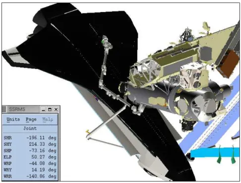
The third scenario adds some of the most challenging requirements and models the transition of the Orbiter from the docked configuration with the ISS to and from the repair work site. Two phases of this operation are shown in Figures 1 and 2.
Specifically, this scenario requires more detailed orbital effects with a modeling of gravity gradient forces, sometimes referred to as tidal or differential gravity effect, in addition to the typically modeled gravity
Figure 1. Orbiter Manevuver to Repair Site
Figure 2. Orbiter Configuration at Repair Site
gradient torques. Due to the relatively large masses of the Orbiter and the ISS end bodies, this tidal effect generates significant forces and torques on the joints of the SRMS. As a direct result, the arm dynamics and orbital dynamics can no longer effectively be modeled as decoupled systems, thus requiring a much more complex integration of the arm and orbital dynamics.
The fourth and final scenario, when the EVA crew person operates at the end of the SSRMS performing repairs on the Orbiter TPS, adds the last set of requirements. These requirements take the form of a long complex chain of interacting elements consisting of the Orbiter attached through the SRMS to the ISS, which is attached through the SSRMS to the EVA crew person, who is applying forces on the Orbiter during the repair procedures. The overall system attitude is maintained by the ISS ACS, which uses a combination of Reaction Control System thrusters and Control Moment Gyros. In addition, there are independent control systems for both the SRMS and SSRMS manipulators. Finally, the EVA crew person applies forces on the Orbiter at the repair work site (refer to Figure 3).
While all of these scenarios could be satisfied with a single complex integrated simulation, it was more efficient to build two separate simulations; the first for Scenarios 1, 2 and 3 and the second for Scenario 4. It was decided to create an independent simulation for the fourth scenario primarily because it was more efficient to reformulate the problem into a single robotic chain (consisting of the Orbiter, SRMS, ISS, SSRMS and EVA crew person) rather than maintain an unnecessarily complex branched topology. It also resulted in an easier simulation configuration process. This resulting simulation is referred to as the ORM Work Site Dynamics (WSD) Simulation and is the principle subject of this paper.
Figure 3. EVA Crew Operating off SSRMS at Potential Repair Site
III.
The ORM WSD Simulation
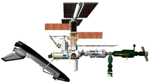
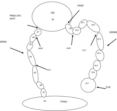
The ORM WSD simulation is designed to model the complex dynamic problem of Orbiter TPS tile repair when it is attached to the ISS with the SRMS. This involves a long dynamic chain of flexible elements in a low Earth orbital environment. This dynamic chain has two orbital bodies of relatively large mass (Orbiter and ISS) connected through a flexible 6 Degree of Freedom (DOF) robotic arm (SRMS). In addition, there is another flexible 7 DOF robotic arm (SSRMS) connected to much smaller mass (EVA crew person). The EVA crew person can apply varying levels of forces at various locations (repair work sites) on the Orbiter (again, refer to Figure 3). This WSD scenario is depicted in Figure 4 and it’s topological representation is shown in Figure 5.
Figure 4. ORM WSD Scenario
The ORM WSD simulation is built using a standardized common simulation architecture developed to simulate systems composed of orbital bodies with robotic elements using the Trick Simulation Environment.1 Trick is a simulation development and operations ‘toolkit’ used extensively throughout the NASA Johnson Space Center (JSC) community for robotic, orbital dynamics, and vehicle guidance, navigations, and control applications. In most Trick-based simululation applications, the robotic and orbital subsystems can be decoupled. However, in some cases, particularly when relatively large massive orbital bodies interact with robotic systems, orbital mechanics affect the robotic response. This architecture and the associated models permits the simulation of the integrated flexible body dynamic response of these types of systems in significant detail.
The Earth environment package used include environment models for Earth time scales, Earth attitude (RNP), non-spherical gravity and atmospheric density. Each orbital vehicle can be propagated independently in both translation and rotation when separated or together as one body when docked. These orbital dynamics models have a well established history of use in orbital simulations at the NASA JSC.
The robotics elements are modeled using a multibody flexible dynamics formulation and algorithmic
Orbiter ISS SRMS SSRMS EVA B7 ELP B6 B5 B4 B3 B2 B1 B0 ELP B17 B16 B15 B14 B13 B12 B11 B10 B9 B8 WRR SHR PMA2 GF2 (port) PDGF
Figure 5. ORM WSD Dual Arm Dynamics Toplogy
age also developed at JSC.2, 3This implementation has been used extensively to model branched topological
chains of flexible robotic manipulators like the SRMS and SSRMS as well as other robotic systems.4
The orbital and multibody dynamics have been linked together with a new set of simulation code that has the orbital package propagate the translational position of the center of mass of the combined system while the multibody package propagates the relative positions of the flexible articulated elements and the rotational state of the combined system. The position of the system center of mass is affected by the geometry and flex of the articulated elements. This is tracked and then used to update the systems structural (or global) reference frame and therefore the position and orientation of the combined system with respect to the system center of mass.
In addition, differences in the Earth’s gravitational attraction to the centers of mass of the orbital bodies is applied to the end points of the robotic systems to account for gravity gradient forces (tidal forces) that generate internal forces on the robotic system that connects the orbital bodes. In this case it represents the forces on the SRMS due to the differential gravitational attraction on the Orbiter and the ISS. This has been shown to be an important factor in SRMS joint torques for the ORM.
IV.
Verification and Validation
One very important question with any simulation, and particularly with more complex simulations, is the question of correctness. How does one verify the formulation of the simulation and validate the results? First, it is important to start with definitions of verification and validation. For purposes of this discussion, verification will be defined as the process of ensuring that the mathematical algorithms and theory upon which the simulations is applicable to the type of problem being modeled. Similarly, for the purposes of this discussion, validation will be defined as the process of ensuring that the algorithms as implemented in
the simulation generate the appropriate results consistent with the theory. In other words, verification is the process of making sure that the applicable theory and algorithms are being used and validation is the process of making sure that the algorithms have been correctly implemented and integrated.
Having said this, the process of verification for the ORM WSD simulation is fairly straightforward. The orbital and multibody flexible dynamics algorithms have been verified against commonly accepted theoretical formulations and found to be both consistent and correct. All of the theoretical basis for the orbital dynamics algorithms is covered in a number of commonly available astrodynamics texts like Bate, Mueller and White5
and Vallado6 and dynamics texts like Goldstein,7 Meriam8 and Greenwood.9 Similarly, the theoretical
basis for the multibody flex dynamics can be found, for example, in Sincarsin and Hughes,10 Hughes and
Sincarsin,11 and Roberson and Schwertassek.12
Unfortunately, the validation process is not quite as straightforward. For simple systems, one can some-times compare outputs to theoretical results. However, this is usually not possible for even moderately complex systems. For the more complex systems, efforts are made to combine verification and validation by comparing against empirical data. Often, when a similar or identical problem is being solved by a separate, accepted and independent simulation, then simulation to simulation comparisons (often called “sim to sim validation”) may be used. If none of these methods are directly available for the problem in question, it is often necessary to resort to a staged or incremental approach with the final step almost always relying on engineering judgement. Unfortunately, the ORM WSD problem resides in this last category, and therefore, the simulation development team took a staged approach to validation.
All the basic dynamics packages have been validated against both theoretical and empirical data. Then the ORM WSD problem being solved by the simulation was broken up into simpler problems with accepted empirical or independent simulated results. These correspond to the following 5 unit-level test cases:
• Orbital Propagation
• SRMS Response
• SSRMS Response
• ORM Verification
• Dual Arm Comparison
The first test case represents checks of the base orbital mechanics results for a simple point mass propa-gated in low Earth orbit. This was compared to sets of independent data from an accepted simulation whose results were previously validated against theory and empirical data. The second test case represents tests of the SRMS subsystem. These results were validated against the results from another accepted simulation used by MacDonald Dettwiler and Associates (formerly SPAR Aerospace) as the hardware provider of the SRMS.13, 14 Moreover, SRMS simulation results have been also verified in the form of ground test and flight data. The third test case represents tests of the SSRMS subsystem. These results were verified against the results from another accepted simulation used by the Canadian Space Agency as the hardware provider of the SSRMS.15 Again, these results were validated against empirical data (ground test and flight). The
fourth test case represents an integrated test of the Orbiter, SRMS and ISS in the ORM configuration. These results were validated against accepted ISS control system behavior and independent simulation results. The fifth test case represents the long chain dynamics of the Orbiter, SRMS, ISS and SSRMS in the ORM WSD configuration. A linear approximation of the dynamics chain was created by removing the nonlinearities from the SRMS and SSRMS manipulator models (such as gearbox backlash and friction). Orbital dynamics and active attitude control effects were excluded. This configuration was then compared to responses provided by Boeing personnel using an independently developed NASTRAN model.
In each test case, the ORM WSD simulation was configured to match the test case scenario and produced the expected results to within accepted tolerances. The final validation step was to run with all effects enabled. The results from these runs were consistent again with engineering expectations.
V.
Conclusions
Numerous simulation design challenges were encountered while developing simulation capabilities to match ORM operational scenarios. Based on these requirements, an incremental build approach was utilized to create a simulation of the ORM worksite dynamics scenario, starting with the subsystem simulation elements and integrating them into increasingly more complex simulations until the resulting ORM WSD simulation had been assembled. Due to the inherent nature of the combined orbital and multibody flexible dynamics problem, a staged verification and validation methodology was developed using subsystem unit-level testing, integrated simulation comparisons, and ultimately fully integrated simulation checkout. The resulting ORM WSD simulation has been successfully used to analyze and investigate issues associated with the Shuttle TPS tile repair procedure as part of RTF contingency operations.
Acknowledgments
The work described in this paper was performed entirely within the Simulation and Graphics Branch of the Automation, Robotics, and Simulation Division of the NASA JSC Engineering Directorate. The authors also wish to acknowledge the NASA JSC Mission Operations Directorate Robotic Systems and the ISS MAGIK Team for providing the graphics images contained within. Finally, the authors would like to recognize the efforts of the Boeing ISS Loads and Dynamics Team for their efforts in supporting ORM WSD linearized dynamics comparisons.
References
1Paddock, E. J., Lin, A., Vetter, K., and Crues, E. Z., “Trick: A Simulation Development Toolkit”,AIAA Modeling and
Simulation Technologies Conference and Exhibit, AIAA 2003-5809, Austin, TX, 2003.
2Ghosh, T. K., and Huynh, A., “Multibody Dynamics for Rigid and Flexible Bodies in a Tree Topology for Space Robotic
Applications”, Technical Memo LMSMS&S-32634, Lockheed-Martin, Houston, TX, 1998.
3Huynh, A., “Formulation and Algorithm for Multi-Flexible-Body Dynamics”, NASA Tech Briefs MSC-22814, Associated
Business Publications, New York, NY, 2000.
4Quiocho, L. J., Huynh, A., and Crues, E. Z., “Application of Multibody Dynamics to On-Orbit Manipulator Simulations”,
to be presented at theASME 2005 International Design Engineering Technical Conferences and Computers and Information in Engineering Conference, DETC2005-85545, Long Beach, CA, 2005.
5Bate, R., Mueller, D., and White, J.,Fundamentals of Astrodynamics, Dover Publications Inc., New York, 1971. 6Vallado, D. A.,Fundamentals of Astrodynamics and Applications, McGraw-Hill, New York, 1997.
7Goldstein, H.,Classical Mechanics, Addison-Wesley Publishing Company, Reading, Massachusett, 2nd ed., 1980. 8Meriam, J. L.,Dynamics, John Wiley & Sons. Inc., New York, si-version, 2nd ed., 1975.
9Greenwood, D. T.,Principles of Dynamics, Prentice-Hall, Inc., Englewood Cliffs, New Jersey, 1965.
10Sincarsin, G. B., and Hughes, P. C., “Dynamics of an Elastic Multibody Chain: Part A - Body Motion Equations”,
Dynamics and Stability of Systems,4, pp. 209-226, 1989.
11Hughes, P. C., and Sincarsin, G. B., “Dynamics of an Elastic Multibody Chain: Part B - Global Dynamics”, Dynamics
and Stability of Systems,4, pp. 227-244, 1989.
12Roberson, R. E., Schwertassek, R.,Dynamics of Multibody Systems, Springer-Verlag, Berlin, 1988.
13Nguyen, P., Ravindran, K., Carr, R., Gossain, D.M., Doetsch, K.H., “Structural Flexibility of the Shuttle Remote
Manipulator System Mechanical Arm”,AIAA Guidance and Control Conference, AIAA 1982-1536, San Diego, CA, 1982.
14Hunter, J. A., Ussher, T. H., and Gossain, D. M., “Structural Dynamic Design Considerations of the Shuttle Remote
Manipulator System”,AIAA Structures, Structural Dynamics and Materials Conference, AIAA 1982-762, New Orleans, LA, 1982.
15Ma, O., Buhariwala, K., Roger, N., MacLean, J., and Carr, R., “MDSF - A Generic Development and Simulation Facility
for Flexible, Complex Robotic Systems”, Robotica,15, pp. 49-62, 1997.