Perception& Psychophysics
1976, Vol. 20(6), 438-444
Model for a three-dimensional optical illusion
M. E. JERNIGAN and M. EDEN
Research Laboratory ofElectronics Massachusetts Institute of Technology Cambridge, Massachusetts 02139
A homogeneous coordinate system is used to describe the transformation from a real three-dimensional stimulustoanillusory three-dimensional perceptual object. The model comprises a series of transformations of which one acts as an illusion operator. The illusion operator is specified by a single parameter whose value determines whether the real or the illusory object is perceived. An experiment to test one prediction derived from the model was performed. The results confirm the prediction.
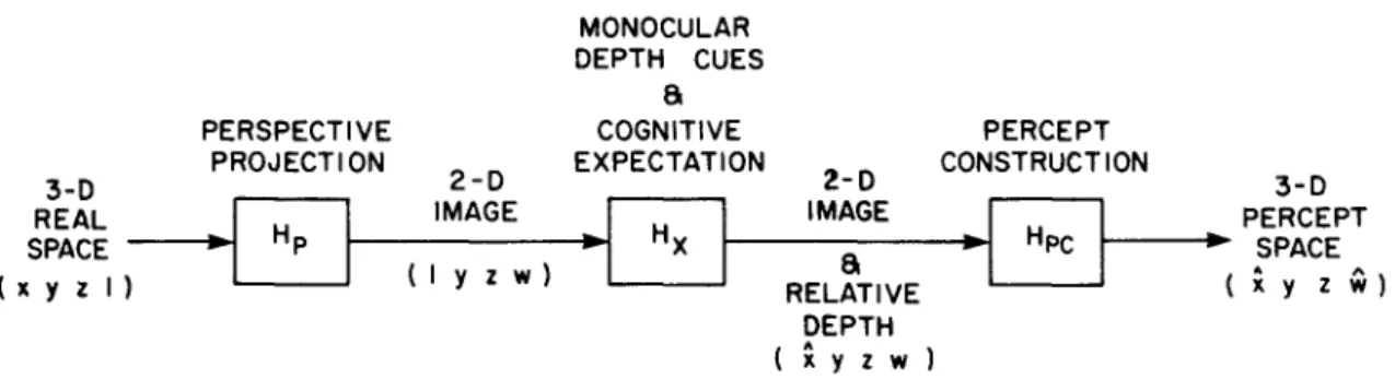
Human monocular depth perception is a complex function of the nature of the stimulus and the previous experience of the observer. Various cues and subjective expectations are employed to con-struct a three-dimensional percept from the two-dimensional image which is the optical projection of the object on the retina. Conceptually, the prob-lem can be structured as in Figure 1. Initially, the object in three-space is mapped to a two-dimensional image by a perspective projection (Hp) .Such a
trans-formation is most conveniently represented in a homogeneous coordinate system, derived from the well-known theory of projective geometry, most recently discussed by Roberts (1963) and Duda and Hart (1973). Such a system employs a fourth co-ordinate as a scale factor. Points in three-space are represented by four-element vectors:
(X,Y,Z)
=
(x,y.z,w)=
VX
=
x/w,y=
y/w, Z=
z/wAn object is represented as a set of points (Vi] and is transformed by postmultiplying by a 4 x 4 matrix H. The perceptual model consists of a sequence of appropriate transformations that map the real object to the perceived object.
The second transformation represents the in-fluence of monocular depth cues and cognitive expectation in reconstructing the depth coordinate lost in the three-space to two-space mapping. Exam-ples of monocular depth cues include relative size, interposition, perspective, texture gradients, etc. Cognitive expectation represents the effect of the observer's past experience on the formation of the percept. Finally, a percept construction operator (Hpc) formulates a three-dimensional percept con-sistent with the two-dimensional image and the relative depth constraints.
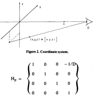
Three-dimensional optical illusions occur when the percept differs in its geometrical description from the object under observation. In the model, the illusion is represented by a modification only of the relative depth constraint operator, Hx• That is, the geometrical description is completely consistent with the perspective transformation. The forms of the 4 x 4 transformation matrices are best revealed by considering the mapping of a point in real space to a point in percept space. Consider the point (x y z 1) in the coordinate system of Figure 2. The perspective projection Hpmaps (x y z) to a point on the y-z plane (the picture plane) from the projection point D on the x axis (the observer's eye). The perspective pro-jection matrix is given by:
PERCEPT CONSTRUCTION Z-D IMAGE MONOCULAR DEPTH CUES
a
COGNITIVE EXPECTATION 2-D IMAGE (Iyzw) a RELATIVE DEPTH (xyzw)Figure 1. Conc:eptual model for monoc:ular depth perc:eption.
PERSPECTIVE PROJECTION 3-D REAL
I
SPACE----i...
Hp (xyzl) 438o
Figure 2. Coordinate system.
I I
I
Ie
-O. FACE OF OBJECTNote that, for a
=
1, percept and object points are identical, implying an accurate perceptual re-construction. Illusions result from the interesting cases when cognitive expectations can produce ana #= 1 which is not too inconsistent with the monocular depth cues.
To clarify the proceeding discussion, consider an example. Construct a three-dimensional object from three identical flat shapes such as that in Figure 3a. Note that each shape has only one right-angle corner. Let the right-angle corners of the shapes be joined to form a right-angle corner in three dimensions, with the obtuse angles projecting toward the ob-server. Figure 3b shows a two-dimensional geometric projection of the object on a plane perpendicular to the subject's line of sight. Viewing monocularly, an observer can easily achieve an illusory percep-tion in which the object appears to invert with the center corner appearing closest to him rather than furthermost. For each object face diagonal, d, there is a unique distance D where the projection of the_ real concave object and the projection of an external (convex) cube are identical. Indeed, regardless of the mathematical theory used to describe the transforma-tion, the projection of the test object is consistent with a cube only at the distance D. That this is true can easily be seen geometricallyin Figure 4. For the 1
o
o
o
o
o
o
-1/Do
16
o
o
o
o
o
o
o
o
o
1o
o
o
o
o
o
I I / I // (',Y,Z) es [.yzI ]This transformation applied to (x y z) results in the two-dimensional image:
[x y z I][Hp] = [x y z (1 - x/D)]
The coordinates in the picture plane are given by y/(l - x/D) and z/(l - x/D) and can easily be verified geometrically. The x coordinate has no meaning at this point since the relative depth constraint represented by H, has not been applied. H, has the form:
The homogeneous coordinate vector for the point in percept space is then:
2
3
' . /
4
b. PROJECTION ON PLANE PERPENDICULAR TO SUBJECT'S LINE OF SIGHT.
1/D 1
o
o
o
o
o
1o
o
o
1o
o
o
Applying this transformation we obtain [ax yZ
(1 - x/D)]. Now the x term contains the relative depth constraint. All that remains is to construct the percept with an inverse perspective projection.
per-440 JERNIGAN AND EDEN x=D o. PERSPECTIVE PROJECTION ILLUSORY OBJECT C D b. CROSS-SECTION. x-z PLANE
Figure 4. (a) Perspective projection. (b)Cross-section, x-z plane. real object and the illusory cube to be consistent the point V4' the lowest point of the real object: and the corresponding point of the illusory cube must be colinear. The line determined by the two points
inter~ects the x axis at only one point, specifying
the distance D.
The object can be represented by an appropriate
se~of points, suchas the seven comers (see Figure4a), with each point a row in an object matrix (7
x
4in this case). For this class of objects, then, the relative depth constraint reflecting an illusory perception can be derived by requiring that the percept correspond-ing to the object [0] be a cube with mutually per-pendicular and equal length edges. Since the real object contains a concave right-angle corner at Vowhich is. mapped under the illusion into a convex right-angle corner, the edge of the perceived cube will be assumed to be equal in length to e, the length of the two edges which make up the right angle of the three shapes which form the stimulus. This assump-tion is equivalent to assuming that the three corners, V., Vl' and
v
3 , corresponding to points 1, 2, and 3of Figure 3b are invariant under the illusion trans-formation. These three points lie in the y-z plane of Figure 4, which is assumed to be the picture plane. Points physically on the picture plane must be in-variant under the illusion transformation if the per-spective projections are to be consistent.
Applying the perspective projection, illusion operator and inverse perspective projection to the stimulus [0] must then produce the cube[C), of edge 3. We have:
The cascade [Hp][Hx][Hp-1] , representing the illusory
perception operator, has thus been specified. EXPERIMENT 1
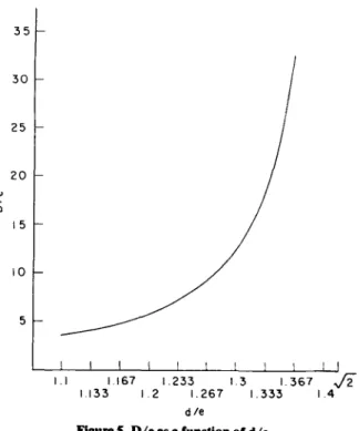
The simplest test of the model is the determina-tion of the distance at which the illusion appears to be a cube. The model predicts a distance, D, as a function of d, the face diagonal, and e, the face edge, given by
I _ VTd/e -
vm
D e -
VT -
dieFigure 5 is a plot of D vs. d in units of e.
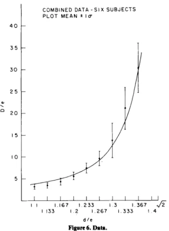
Six Boston area graduate students were paid to act as subjects for the experiment. All were in their mid-20s and had' normal or fully corrected vision. Nine objects, varying in the length of the diagonal of the three planar shapes (d in Figure 3a) were con-structed (d
=
3.3, 3.4, ..., 4.1 in.; e=
3.0 in.). Object faces were sections of Formica, white with a light green unstructured pattern. The objects were mounted on a stand which could be moved along an optical bench by means of a string, pulley, and crank arrangement. By turning the crank, the subject could position the object anywhere in a range from almost touching his head to 148 in. away. Each subject was presented each object 10times. The order of presentation of the objects was randomized.The subject's task was to obtain the illusion and position the object at the point (distance along the visual axis) where it looked most like a cube. The results are plotted in Figure 6, showing mean
35 30 25 20 '" "-a 15 10
[C) is a 7
x
4 matrix whose rows correspond to the seven corners of an external cube. This constraint yields -d a = - - - - -2d - ..;-'Ie 5 1.1 1.167 1.233 13 1133 12 1.267 1.333 dIeCOMBINED DATA -SIX SUBJECTS PLOT MEAN ±Ia 40 35 30 25 '" "-CI 20 15
smaller than expected standard deviation for large values of D may be partly attributed to limitations in the experimental setup. Subjects were aware of the maximum distance setting and their judgments may have been effected by such knowledge. In searching for the correct position, subjects felt the object come up against the end of the optical bench. A longer bench would have allowed greater variation.
EXPERIMENT 2
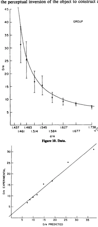
A second class of objects, similar to the first class, but differing in two aspects, has been sub-jected to the same experimental test. In this case, the faces have a diagonal d
>
V2e, with each..J « !z 20 w ::!i ii: w ~ 15 w 25 '" <, CI 30 5 I 1 I 167 1233 1 3 I 367 1133 12 1.267 1.333 I die Figure 6. Data. 10 10 8+ o 8-O' GROUP STANDARD DEVIATION 4 2 12 10 8 8 6 5 5 10 15 20 25 30 DIe PREDICTED
Figure 7. Plot of experimental vs, predicted value of Die for Experiment 1. The line of best fit isgiven by Y= .9837 X + .1436,and the correlation coefficientisr = .9899.
o "---'---'---_--'-__"--_--'---_--'-_---.JL-_-'---_ _
o 5 10 15 20 25 30 35
D
Figure 8. d, the distance from the point of cube projection (D) that the object mustbemoved to obtain a ljzochange in the angle
of the right-side-edge projection in the picture plane. d': toward observer; d-: away from observer.
position and indicating standard deviation for each object.
An alternate presentation of the results is given in Figure 7, where the experimental values are plotted against the predicted values of the distance D. A linear regression analysis results in the equation for the line of best fit: Y = .9837 X
+
.1436. The correlation coefficient is .9899.The results are in general agreement with the model. Variations from the prediction are primarily due to the difficulty of the task. The judgment of cubeness is itself subject to variation, particularly at greater distances from the subject where a relatively large change in D results in a relatively small change in the projection. For smaller d (3.3 to 3.5 in.), the object is fairly close to the subject and the illusion is difficult to maintain. One expects that the subject's ability to judge geometrical relation-ships between object face edges would be related to the variation in his judgment of cubeness as reflected by the standard deviation of his estimate of D. A straightforward geometrical calculation yields the offset (relative to D) necessary to obtain a Yz0 change
in the angle of the edge projection. Figure 8 shows the result with d representing the offset. Super-imposed are data points indicating standard devia-tion. There appears to be some evidence that the subjective criterion of cubeness may be related to judgment of parallelism for the face edges. The
442 JERNIGAN AND EDEN
Figure 9. In this case, tbe objectIsformed from tbree identical facesISbefore; bowever, sides 1 and 2 are common to eacb of two faces, and Aistbe center vertex common to all tbree faces.
d/3e
+
[(V2die - 1)2 - 113)1/2 Die= -"
die -V2
10 15 20..
"-o 30 35 25 40 45mapping is many-to-one; why should one particular percept result from illusory perception? We have derived an illusion operator that seems to apply at the point where the object projects under perspective as a cube. Does the same operator apply at other distances from the observer? At the point of cube projection, one might argue that cognitiveexpecta-tion-cubes being overlearned objects-constrains the perceptual inversion of the object to construct a
e
...
external face angle being a right angle. In addition, the faces are joined with the acute angle meeting at the internal vertex, resulting in the faces not being perpendicular to each other as was the case for the first objects. Figure 9 shows the object face. The computed distance of cube projection is:
with a relative depth constraint a of: 5
5 10 15 20 25 30 35
Ole PREDICTED
Figure 11. Plot of experimental vs, predicted value of Ole for Experiment 2. Tbe line of best fit is given by Y= .8253 X
+1.5545, and tbe correlation coefficientisr = .9893.
1.627 1.73~ 1.677 1.437 1.483 1.545 1.461 1.514 1.584 dIe Figure 10. Data. 5 ..J ~ 20 w ~ il: w ~ 15 w ~ 25 30 10 -d/v'3e [(v'2die - 1)2 - 113)1/2
Figure 10 shows data from three subjects taken in a manner similar to that for the first class of objects. The computed distance of cube projection is also plotted.
A plot of experimental vs. predicted value of the distance D is shown in Figure 11. The line of best fit is given by Y
=
.8253 X+
1.5545, and the correlation coefficient is .9893.As in the first case, the data agrees reasonably well with the computed values of the point of cube projection. The added inclination between object faces for the second group may contribute to the difficulty of maintaining the illusion. This would be reflected by less reliable cube judgments and may account for the greater variation in the results of the second group. The effect of the limited length .of the optical bench is again evident in the object
having a large value of D.
As a prelude to discussing further experiments, consider a few observations on the nature of these particular illusions. The perspective projection
a =
cube. At all other distances, the illusory appearance has no such precise cognitive expectation to support it. In the model, the fact that a unique illusory percept is obtained is reflected by the unique value of a, the relative depth constraint, for a given test object. At distances other than D, the value of a
corresponds to a constraint of minimum perceptual distortion of relative depth. Of all possible three-dimensional objects consistent with the perspective projection, the one perceived is that closest to the expected cube. The uniqueness ofa in the operator can be tested as follows. The illusion appears to be edge dominant, i.e., independent of surface features of the three faces. By inscribing a quadrilateral on a surface that the illusion operator predicts will appear rectangular at some distance other than D, the cube point, and presenting the task to an observer, the illusion operator can be verified.
An important characteristic of the model is the plane of inversion. This can be tested by asking the subject to estimate the distance of various points on the object. In keeping with our minimum per-ceptual distortion constraint, we expect points
v
Itv
2,V3,the three corners which lie in the picture plane(see Figure 4), to be invariant under the transforma-tion, and the subject to be nearly correct in placing a markerinthe plane of
v
tt V2,and V3. Unfortunately, this test has not yet been performed in any rigorous fashion, although informal tests are encouraging.Similar experiments will determine the value ofa,
the relative depth constraint as a function of the absolute distance D of the object. The model yields an xp coordinate for percept space of:
ax
xp
=
1+
(a - 1)x/D Solving for awe obtain:xp (D - x) x(D - xp)
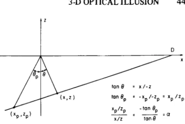
This may be empirically checked by asking the observer for depth estimates with a suitable indicator arrangement. D • xI-z • -xpI-Zp • xpIZp - tan8p • tan8 •a
Figure 12. Interpretation of the parametera.
A comparison of the relative depth constraints for the two classes of objects constructed from the shapes of Figures 3 and 8 reveals a simple geometrical relationship connecting real object and illusory object through a. Consider Figure 12 and the basic transformation (x yz1) ....[x y z(l
+
(a - 1)x/D)] In percept space: ax x -p - 1+
(a - '1)x/D and z zp=
1+
(0- - 1)x/D Note xp/zp=
ox/z and xp/zp tan 9p 0 ' = = -x/z tan 9In the last expression, the angles 9 and 9p are the angles between the vector defining the points in real
OBJECT
H
p
H
x
H
-Ip
PERCEPT"
a
COGNITIVE EXPECTATION
444 JERNIGAN AND EDEN
space and perceptual space, respectively, and the picture plane. The perceptual inversion that results in the illusion corresponds to a folding through the plane of inversion defined by the picture plane, where the parameter a determines the relationship between the angle in percept space and that in real space.
The addition of a feedback path to Figure I representing the effects of expectation is shown in Figure 12. That cognitive expectation is a powerful factor in determining Hx,the relative depth operator,
is clear from noting that the illusion can be held in spite of contradictory monocular depth cues. More significantly, motion parallax can be ignored, with the observer accepting a highly unusual object move-ment in response to his own head movemove-ment while retaining the illusory percept. An interesting explora-tion of the cognitive expectaexplora-tion concept would involve reversing object and percept. That is, present the observer with a perfect external cube and ask him to obtain a concave noncube illusion. One might compare ease of inversion and frequency of illusory percept as measures of the relative cognitive expecta-tion of convex cubes and concave noncubes. The
effect of concave vs. convex could be explored by presenting a convex noncube and attempting to elicit a concave cube, illusory percept.
In summary, we have made some speculations concerning the transformation from a real-world stimulus to an illusory percept. The mathematics of homogeneous coordinates is a useful framework for describing the perspective projection and provides an elegant description of the illusion operator specified by a single parameter. One prediction which is easily derived is the distance at which a real object, constructed from nonsquare shapes, should appear as a three-dimensional cube under the illusion transformation. The experimental data tend to confirm the prediction.
REFERENCES
DUDA, R. 0., & HART, P. E. Pattern classification and scene analysis. New York: Wiley, 1973.
ROBERTS, L. Machine perception of three dimensional solids. In J. T. Tippett et aI. (Eds.), Optical and electro-optical
infor-motion processing. Cambridge, Mass: M.LT. Press, 1963.
(Received for publication September 19, 1975; revision accepted August 25, 1976.)