University
of
Cape
Town
Improving Fractional Frequency Reuse (FFR) for
Interference Mitigation in Multi-tier 4G Wireless Networks
Oluwadamilare Daniel, Adeyemo
This thesis is submitted in partial fulfilment of the academic requirements for the degree of
The copyright of this thesis vests in the author. No
quotation from it or information derived from it is to be
published without full acknowledgement of the source.
The thesis is to be used for private study or
non-commercial research purposes only.
Published by the University of Cape Town (UCT) in terms
of the non-exclusive license granted to UCT by the author.
As the candidate’s supervisor, I have approved this dissertation for submission.
Name: Dr. Mqhele E. Dlodlo, Associate Professor
Signed: ______________________ Date: ________________________
Declaration
I declare that this thesis is my own work. Where collaboration with other people has taken place, or material generated by other researchers is included, the parties and/or materials are indicated in the acknowledgements or are explicitly stated with references as appropriate.
This work is being submitted for the Master of Science in Electrical Engineering at the University of Cape Town. It has not been submitted to any other university for any other degree or examination.
Oluwadamilare Daniel ADEYEMO 19/12/2014
Dedication
…To the Glory of God Almighty, who has our days written out in His Book
Abstract
The need to provide quality indoor coverage for mobile network users in an indoor environment has become paramount to communication service providers (CSPs). Femto-cells due to their low capital expenditure (CAPEX) and operating expenditure (OPEX) have seen widespread adoption as a possible solution to the indoor coverage challenge. The major drawback of its adoption is the possibility of erratic but significant interference to both the Femto-cell and the Macro-cell tiers owing to their Ad-hoc mode of deployment.
The Fractional Frequency Reuse (FFR) is an interference mitigation scheme, due to its effectiveness and low complexity; it has been proposed to be an efficient technique of solving the problem of interference in the cross-boundary region. In this study, a critical analysis of the existing schemes revealed that Femto-cell users at the border between the cell centre region (CCR) and the cell edge region (CER) suffer cross-boundary interference. An algorithm that integrates a buffer zone between the existing CCR and CER has been developed to solve the cross-boundary interference challenge experienced by the Femto-cell users.
A system level simulation implemented in MATLAB was used to evaluate the developed algorithm. The network performance (in terms of user-achieved signal-to-interference-plus-noise ratio (SINR) and its daughter metrics such as channel capacity and throughput) was estimated. In terms of the SINR, the performance improvement recorded for Femto-cell users at the border region after the implementation of the buffer zone was more than eighty per cent (80%). There were significant improvements in terms of the channel capacity and throughput for the Femto-users present at the buffer region with the implementation of the developed algorithm.
The Hybrid frequency reuse concept was incorporated into the proposed scheme to determine the extent of the buffer region in the cell and ensure fair reuse of resource blocks (RBs) between the Femto-cell users at the CCR and those at the CER. The granularity with which spectral resources can be allocated to subscribers in the Orthogonal Frequency Division Multiple Access (OFDMA) physical layer of the fourth generation communication network was exploited in the development of the proposed scheme.
Finally, the FFR with buffer scheme ensures overall quality of experience improvement for network subscribers at both tiers of the network with an expected minimal increase in control plane signalling between the nodes present in the network.
Acknowledgement
First and foremost, I thank my supervisor, Prof M.E. Dlodlo for the fatherly role he played throughout the duration of my studies in the COMMED research group. I really appreciate his listening ears, gentle and constructive criticism which gradually nudged me in understanding the principles of academic research in the diverse field of Electrical Engineering.
Secondly, I thank my Uncle, Professor John Olaomi, for his efforts in facilitating my admission into the programme, his unwavering display of encouragement and financial support during the course of the program. God bless you.
My research colleagues at the COMMED group including Dayo, Henry, McBath, Joshua, Frederick, Charles, Bernard, Wiseman, Nixon, I see you all as friends from all over Africa and it has been a great joy to know and interact with you all.
My appreciation also goes to Mr Lateef Akinyemi for his availability, honest comments and technical inputs. Also, Samson, you have been like a brother to me even away from home, thanks for being you.
Dr Tony Adefuye and his family, thank you all for making my residential experience in Cape Town a convenient one, God bless you.
Finally, my siblings, Oluwafunmilola, Oluwaseyi and little Aanuoluwapo, I can never wish for a better set of teammates, you people are the best ever. We will keep moving forward.
Table of Contents
Declaration ... iii
Dedication ... iv
Abstract ...v
Acknowledgement ... vii
List of Figures ... xii
List of Tables ... xv
List of Acronyms ... xvi
1 Introduction ...1
1.1 Cellular Communication ... 1
1.2 Heterogeneous and Multi-tier Networks ... 3
1.3 The Indoor Coverage Challenge ... 5
1.4 Interference Mitigation with Spectrum Reuse... 7
1.5 Fractional Frequency Reuse (FFR) ... 7
1.6 Aim and Objectives ... 8
1.7 Research Questions ... 9
1.8 Scope of Research ... 9
1.9 Dissertation Outline ... 9
1.10 Chapter Summary ... 10
2 Indoor Communication and 4G Femto-cells Overview ... 11
2.1 Chapter introduction ... 11
2.2 Improving Indoor Communication... 11
2.3.5 Pico-cells ... 15
2.3.6 Femto-Cells... 15
2.4 Self-Configuration ... 18
2.5 Self-Optimization ... 18
2.6 Self-Healing ... 18
2.7 Femto-cells Operating Modes ... 19
2.8 Advantages of Femto-cells ... 19
2.9 LTE Femto-Cell Physical Layer Structure ... 20
2.9.1 OFDM/OFDMA ... 20
2.9.2 OFDMA Resource Grid Structure ... 21
2.10 LTE Femto-Cell Logical Architectures ... 24
2.11 Chapter Summary ... 26
3 Literature Review ... 28
3.1 Chapter Introduction ... 28
3.2 The Vienna LTE Simulator ... 28
3.2.1 Scenario 1: Macro-cell only deployment ... 30
3.2.2 Scenario 2: Femto-cells overlaid on Macro-cell. ... 30
3.2 Interference Categorization ... 34
3.2.1 Cross-Tier Interference ... 34
3.2.2 Co-Tier Interference... 34
3.3 Interference Management in Heterogeneous Networks ... 35
3.3.1 Clustering of Femto-cells ... 36
3.3.2 Cooperative Frequency Scheduling ... 38
3.3.3 Cognitive Techniques ... 40
3.3.4 Beam forming ... 42
3.3.5 Power Control Techniques ... 43
3.3.6 Considerations for MIMO implementation ... 44
3.4 Fractional Frequency Reuse ... 44
3.4.1 Strict-Fractional Frequency Reuse ... 45
3.4.2 Soft Fractional Frequency Reuse... 46
3.4.3 FFR-3 Scheme ... 47
3.5 Interference Challenge in FFR-3 Scheme ... 48
4 System Design and Parameters ... 50
4.1 Introduction ... 50
4.2 Indoor Propagation ... 50
4.3 Adopted Empirical Path loss Models ... 52
4.4 Analytical and Simulation System Model ... 52
4.5 The Buffer Zone ... 56
4.6 Proposed Hybrid Spectrum Sharing Scheme ... 56
4.6.1 The Scaling Parameter (
) ... 604.7 Network Scenarios... 61
4.7.1 Single Cell Multi-Tier Implementation ... 61
4.7.2 Multi-Cell Multi-Tier Implementation ... 62
4.8 Chapter Summary ... 68
5 Results, Discussion of Results and Analyses ... 69
5.1 Introduction ... 69
5.2 Performance Metrics ... 69
5.2.1 Signal to Interference plus Noise Ratio (SINR) ... 69
5.2.2 Ergodic Capacity ... 70
5.2.3 Users Throughput ... 70
5.3 Analytical Evaluation ... 70
5.3.1 Single Cell-Multi-tier Network Scenario ... 71
5.3.2 Multi-cell-Multi-Tier Network Scenario ... 75
5.4 Simulation Evaluation ... 77
5.4.1 Achieved SINR ... 77
5.4.2 Users Throughput ... 79
5.5 Buffer Zone Radius Estimation ... 80
5.6 Chapter Summary ... 84
Appendix A ... 93
A.1 The Access Stratum of the OSI reference Model and Protocols in LTE. ... 93
A.1.1 The Data-Link Layer ... 95
A.1.2 The Physical (PHY) layer ... 97
Appendix B ... 100
List of Figures
Figure 1.1: The cell-shrinking concept ...1
Figure 1.2: Compositional Structure of Heterogeneous Networks [4] ...4
Figure 1.3: Multi-tier Network Concept [4] ...5
Figure 1.4: Global mobile traffic forecast (Cisco VNI) [8] ...6
Figure 2.1: Distributed Antenna System in a 3-floor Building adapted from [16] ... 13
Figure 2.2: Radiating or Leaky Cable in a 3-floor building [16] ... 14
Figure 2.3: Femto Base Stations in a 3-floor building adapted from [16] ... 16
Figure 2.4: OFDMA Subcarriers ... 23
Figure 2.5: LTE Resource allocation Illustration in the Time and Frequency domain ... 23
Figure 2.6: LTE Frame Structure ... 23
Figure 2.7: LTE Femto-cell Logical architecture (Variant 1) [23] ... 24
Figure 2.8: Femto-cell Logical architecture (Variant 2) [23] ... 25
Figure 2.9: Femto-cell architecture (Variant 3) [23] ... 26
Figure 3.1: Macro-cell only scenario ... 30
Figure 3.6: Co-tier interference management through cognitive approach ... 41
Figure 3.7: Interference mitigation using beam forming [16] ... 43
Figure 3.8: Strict FFR with N = 3 ... 46
Figure 3.9: Soft FFR with N = 3 ... 47
Figure 3.10: 3-cells layout of FFR-3 scheme ... 48
Figure 4.1: Typical Regions of a Single Sector in the Proposed Scheme ... 56
Figure 4.2: Frequency allocation in the proposed FFR-3 with buffer scheme. ... 64
Figure 4.3: Signalling Flow-Chart for the Proposed FFR-3 with buffer Scheme. ... 67
Figure 5.1: FFR-3 with Buffer ... 71
Figure 5.2: FFR-3, no buffer with MeNB contributing Interference ... 72
Figure 5.3: FFR-3, buffered to prevent MeNB interference ... 72
Figure 5.4: FFR-3, buffer implemented and HUEs sharing same Sub-band at the CER ... 73
Figure 5.5: Path loss (dB) experienced by Macro and Femto User against distance ... 73
Figure 5.6: Single Cell achieved channel capacity with the different scenarios ... 74
Figure 5.7: Basic Illustration of simulation setup for seven-cells Network with FFR-3... 76
Figure 5.8: 7 cells layout achieved average channel capacity for the three scenarios (bps) ... 76
Figure 5.9: Achieved SINR of HUEs ... 77
Figure 5.10: Per User Channel capacity of FFR-3 with and without buffer ... 78
Figure 5.12: Buffer region estimation (
= 1.0) ... 81Figure 5.13: Buffer Region Estimation (
= 1.25) ... 81Figure 5.14: Buffer Region Estimation (
= 1.5) ... 82Figure 5.15: Buffer Region Estimation (
= 1.75) ... 82Figure 5.16: Buffer Region Estimation (
= 2.0) ... 83Figure A.1: The LTE Protocol Stack ………...………....………....94
Figure A.2: Data flow and resource mapping in LTE ………….………...…...95
Figure A.3: Logical layout of the MAC layer……….………...………97
List of Tables
Table 1.1: Theoretical data-rates of mobile communication technology generations [3] ....2
Table 2.1: Power and coverage comparison of Base station types ... 16
Table 2.2: Structural comparison of Pico-cell and Femto-cell ... 17
Table 3.1: Interference Scenarios ... 35
Table 4.1: Indoor Services and their propagation impairments [45] ... 51
List of Acronyms
3GPP 3rd Generation Partnership Project ADC Analog to Digital Converter
AMC Adaptive Modulation and Coding
ASE Area Spectral Efficiency
CA Carrier Aggregation
CAPEX Capital Expenditure
CCR Cell Centre Region CER Cell Edge Region CP Cyclic Prefix
CQI Channel Quality Indicator
CRBM Cognitive Resource Block Management CSG Closed Subscriber Group
CSI Channel State Information CSP Communication Service Provider DAS Distributed Antenna System FDD Frequency Division Duplex
LTE-A Long Term Evolution-Advanced MAC Media Access Control
MeNB Macro enhanced Node B MIMO Multiple Input Multiple Output MME Mobile Management Entity MUE Macro User Equipment
OFDMA Orthogonal Frequency Division Multiple Access OSG Open Subscriber Group
OSI Open System Interconnection OPEX Operational Expenditure PHY Physical Layer
QoS Quality of Service
RF Radio Frequency
ROI Region of Interest
SC-FDMA Single Carrier-Frequency Division Multiple Access SCTP Stream Control Transport Protocol
S-GW Serving Gateway
SON Self Organizing Network
SINR Signal to Interference plus Noise Ratio TDMA Time Division Multiple Access
TDD Time Division Duplex TTI Transmission Time Interval
UE User Equipment
Chapter 1
1
Introduction
1.1 Cellular Communication
The challenge of provisioning quality data rate to subscribers has caused the telecommunications network field to be subject to constant but gradual development. The increasing number of subscribers and proliferation of gadgets such as smart phones, tablets and laptops that constantly request bandwidth intensive services such as video on demand (VOD), online gaming and other social networking activities, have kept the pressure up on mobile communication technologies. This has ensured their constant evolution in terms of providing better quality of service (QoS) and reliability to users [1],[2].
R r r r r r r r
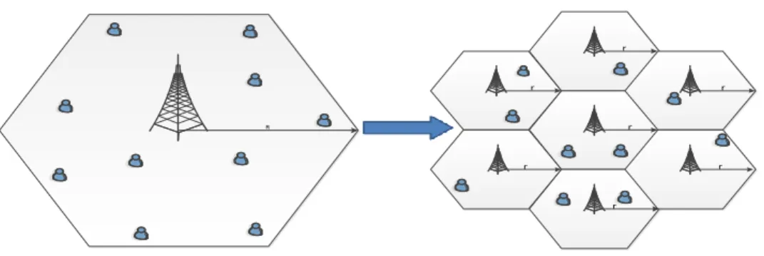
Figure 1.1: The Cell-shrinking concept
The concepts of cell shrinking i.e. replacing high power base station covering a large geographical area with more low power transmitters is illustrated in Fig. 1.1. Cell shrinking
efficiency (ASE) and ensures improved quality of experience for end users but the cohabitation of different cell sizes with the frequency reuse concept give rise to interference.
Improving interference mitigation schemes is crucial and its combination with other areas of communication systems such as coding, modulation and multiple access schemes has helped to enhance network performance. This is evident in terms of theoretically achievable data rate of generational evolution of communication technologies depicted in Table 1.1 [3]
Table 1.1: Theoretical data-rates of mobile communication technology generations [4] Network Generations Approximate Data Rate 1G 28 – 56 Kbps 2G 144 Kbps 3G 0.384 – 2 Mbps 4G 0.1 – 1 Gbps
First generation (1G) networks used frequency division multiple access (FDMA) physical (PHY) layer technology. FDMA divides the frequency spectrum into channels. The adjacent channel interference can result if proper mitigation approach is not implemented. Therefore, guard bands are incorporated between consecutive channels to prevent the adjacent channel interference. The introduction of the guard bands, while effectively reducing adjacent channel interference, leads to inefficient spectral usage in FDMA.
Second generation (2G) systems make use of time division multiple access (TDMA) whereby resources are allocated to users in time. The time component is split into slots that are accessed by the users in a periodic manner. Legacy frequency reuse schemes are used to perform interference management activities and to ensure high desired signal content at the receiver.
Third generation (3G) networks employed code division multiple access (CDMA) scheme at the physical (PHY) layer of the open system interconnection (OSI) model. Here, resource allocation is not done in time or frequency but orthogonal codes are used to spread signal energy over the frequency spectrum in order to allow multiple users to be separated at the receiver. The 3G networks are interference-limited with the system requiring effective power control algorithms so as to prevent the users from degrading the channel conditions of each other and causing reduction in capacity. For Fourth Generation (4G) systems, the location of resource allocation protocols has been illustrated in Appendix A in terms of OFDMA.
The Fourth generation (4G) networks utilized the technology of orthogonal frequency division multiple access (OFDMA) at its physical (PHY) layer. The multi-carrier and narrow band nature of this technique makes the implementation of different interference mitigation schemes with varying degree of complexities possible.
1.2 Heterogeneous and Multi-tier Networks
A typical communication service provider’s (CSP) network which comprises different mobile communication technologies is illustrated in Fig. 1.2 [4]. The Heterogeneous networks are an attractive means of improving mobile network capacity. A HetNet typically consists of multiple radio access technologies, architectures, transmission solution with varying transmission power [5].
Figure 1.2: Compositional Structure of Heterogeneous Networks [4]
The Multi-tier Networks illustrated in Fig. 1.2 and Fig. 1.3 [4] can be regarded as a subset of heterogeneous networks whereby for a single CSP, radio access techniques varying in their transmission power are deployed to provide coverage to subscribers in order to ensure that the quality of service (QoS) requirements of the users’ applications are satisfied by the network.
They are deployed overlying each other in a geographical region and the concept of cell shrinking explained earlier is exploited to improve wireless capacity of the network [6].
Figure 1.3: Multi-tier Network Concept [4]
With Multi-tier networks, if all the tiers are open, users can easily connect to the tier that provides the best Signal to Interference plus Noise Ratio (SINR) and a maximised network performance can be experienced by the subscribers at all times.
1.3 The Indoor Coverage Challenge
Due to signal attenuation with respect to distance, multipath fading and wall losses, radio waves used suffer heavy degradation in signal strength or amplitude as they cross over from the outdoor to the indoor environment, but the need for CSPs to provide high data rate communication in indoor areas cannot be overemphasized.
traffic will be video traffic[8]. All these factors when combined together make providing quality indoor coverage a priority for network operators. Furthermore, the new networking paradigm of machine to machine (M2M) communications and the Internet of Things (IoT), which will give rise to applications that will see heavy deployment in indoor environments such as smart homes and other industrial applications (e.g. robotics control in factories) are also some reasons buttressing the push for a better coverage in indoor areas.
Figure 1.4: Global mobile traffic forecast (Cisco VNI) [8]
Femto-cells which are small base stations with relatively low transmit power and small radius of coverage have been proposed to solve the indoor coverage problem in a cost-efficient manner. Femto-cell networks deployment will face challenges that current standards are yet to address. By examining the OSI protocol stack, critical performance issues are likely to evolve at the physical (PHY) and transport layer. The physical (PHY) layer challenges will also affect media access control (MAC) layer and will involve issues regarding radio resource management and interference mitigation. For the transport layer, issues of concern to network designer are traffic load balancing between the Macro-cell and Femto-cell tiers, mobility management, backhaul congestion management and optimization of control plane signalling. In this dissertation, the focus will be on the interference mitigation at the physical (PHY) layer.
1.4 Interference Mitigation with Spectrum Reuse
When two or more wireless communication instances are initiated in a multi-tier network on the same channel, interference occurs and it adversely affects the overall network performance even leading to total outage at the target receiver if the total interfering signal power supersedes that of the desired signal. In order to solve the interference problem, partitioned (fixed) reuse and shared reuse have been considered for a multi-tier network consisting of Macro-cells and Femto-cells [6], [9],[10]. The partitioned reuse mode divides the available spectrum into two separate portions, which are then used by each network tier. Adopting partitioned reuse ensures that interference between tiers of the network is significantly reduced. The demerit of this approach is that underutilization of the spectra resources in either tier of the network can occur.
The second approach shares the frequency resource between the two tiers of the network i.e. full inter-tier frequency reuse. This provides higher capacity but also increases the exposure of network nodes to inter-tier interference. Since the Femto-cells have a tight constraint on the available transmit power and they access the spectrum using similar technique of underlay spectrum access of the cognitive radio paradigm, they suffer more from significant interference contributed by the Macro-cell tier.
With the PHY layer technology of OFDMA for 4G networks, legacy interference mitigation techniques can further be optimised to provide better interference mitigation schemes that are very efficient and results to lesser reduction in trunking capacity per cell. This is because Orthogonal Frequency Division Multiple Access (OFDMA), through the usage of narrowband subcarriers, provides a more granular means of allocating radio resources to users in the network in both time and frequency.
channel capacity that a single cell can provide to users in its coverage region and often times, trade off needs to be made between the trunking capacity that is desired per cell and the level of interference exposure that network designers want for users to be exposed.
Fractional frequency reuse builds on the traditional frequency reuse schemes and it strives to improve the spectrum available per cell while keeping the interference levels at bearable minimum. N.Saquib et al. in [12] and Lee et al. in [13] adopted FFR to multi-tier networks containing Macro-cells and Femto-cells. Their analyses showed the effectiveness of the adoption of FFR schemes to mitigate interference. FFR requires minimal information exchange between the tiers that constitute the network making it perfectly suitable for Femto-cells that will be unable to pack complicated circuitry due to its reduced price. FFR is also suitable for interference mitigation on both uplink and downlink. The existing FFR designs failed to provide a suitable mechanism to cater for user equipment connected to Femto-cells at the boundary region between the CCR and the CER and this was clearly pointed out by the authors of [12]. It is therefore paramount to look for ways of mitigating this cross-boundary interference and create a more optimized FFR scheme for multi-tier networks.
1.6 Aim and Objectives
In this research work, critical consideration of the FFR techniques that are in existence will be carried out. Furthermore, a method of overcoming the cross-boundary interference difficulty that mars the performance of currently existing frameworks will be proposed. The research objectives are;
To investigate the performance degradation caused by overlaying Femto-cells on a Macro-cell network with each tier reusing the spectral resources of each other.
To implement a FFR scheme that incorporates a cell centre region 2 (CCR2) or buffer zone into a mobile cellular network.
To determine the optimal radius or area of the buffer zone taking into consideration relevant and realistic network constraints and assumptions.
1.7 Research Questions
What level of performance degradation can be expected if Femto-cells are overlaid on the same spectral infrastructure as with a Macro-base station in a single cell?
What level of improvement can be achieved in terms of per user capacity and throughput if a buffer zone is incorporated into the existing FFR-3 scheme at the boundary region between the pre-existing cell centre and cell edge region?
What will be the optimal radius (area) for the cell centre region 2 (Buffer zone) at which the performance of the network is maximised for the users of both tiers present in the network?
1.8 Scope of Research
This research considers mainly multi-tier networks that consist of a Macro-cell tier and a Femto-cell tier only. The hexagonal cellular model is used for all analytical activities and relay tiers were not considered. All analyses and simulations implemented are system level simulations unless if otherwise stated. The two tiers of the network both implement the OFDMA physical layer as the multiple access technique.
1.9 Dissertation Outline
In this chapter, the future traffic pattern was discussed to buttress the drive for better coverage in indoor environment by CSPs. A concise introduction to the concept of heterogeneous cellular communication networks with emphasis on interference mitigation and considerations for Femto-cell deployment was also given. The problem of interference was highlighted and the benefits attached with this study were stated.
this dissertation is based on were studied with emphasis on its PHY layer technology and resource allocation to network subscribers.
Chapter 3 discusses interference in multi-tier networks, and the various mitigation approaches that exist in literature with their merits and demerits. The concept of frequency reuse for interference mitigation in single tier networks and modification attempts for multi-tier networks were highlighted.
Chapter 4 presents clearly the proposed algorithm for the FFR-3 with the buffer technique to solve the identified challenge with minimal additional overhead for the multi-tier network. Discussions about the analytical derivation of system parameters and resource partitioning for users belonging to each tier of the networks were also presented.
In chapter 5, MATLAB codes developed from our algorithm were used to perform system level simulations to demonstrate the improvement in performance that the FFR-3 with buffer technique has on the network. A single cell Macro-cell-Femto-cell network was initially analysed before extending the analysis to a seven-cell network. The Signal to Interference plus noise ratio (SINR), system capacity and throughput were some of the performance metrics evaluated.
Chapter 6 gives the concluding remarks. Concise discussions relating to the performance of the proposed FFR-3 with buffer technique were presented and future works that could be done in line with our analyses were put forward.
1.10
Chapter Summary
This chapter has given a brief but concise insight into mobile communication technologies, focussing on the need to provide improved data rate and its relationship with interference mitigation. The need to provide quality radio access to indoor users due to increment in indoor traffic and the solution provided by Femto-cells deployment were highlighted. Discussions regarding the interference challenge that the co-channel deployment of Femto-cells posed to the whole network was presented, as well as the need to improve the already existing frameworks in order to make them more robust and efficient.
Chapter 2
2
Indoor Communication and 4G Femto-cells Overview
2.1
Chapter introduction
In this chapter, a holistic approach is taken to present the challenges that face indoor wireless communication. The solutions that have been proposed were examined and their associated strengths and weaknesses, which led to the proposal of Femto-cells, were pointed out. The air interface (OFDMA) of LTE Femto-cells as it pertains to resource allocation was discussed. Furthermore, the logical architectures that are needed to be considered when integrating the Femto-cells into an existing network were also presented.
2.2
Improving Indoor Communication
With the shortcomings of the regular Macro-cells to serve subscribers in indoor environment efficiently becoming evident, CSPs decided to implement solutions that can effectively tackle this problem and provide high quality coverage to subscribers in indoor environments. The proposed solutions can be broadly categorized into Outdoor approach and Indoor approach. These are discussed in the succeeding sections.
2.3
Outdoor Approach
This method seeks to improve indoor signal quality by increasing the quality of the outdoor signals in order to reduce the attenuation suffered by electromagnetic waves as they cross over from the outdoor to the indoor environment. More Macro-cells or outdoor micro-cells could
2.4
Indoor Approach
The need to optimize radio coverage directly in indoor environment led to the development of the following systems for the improvement of indoor radio propagation.
2.4.1
Indoor Repeaters
These devices extend the coverage area of a cell. They are useful in areas which are sparsely populated with limited network coverage. They can also be used to enhance the capacity of a network at cell edges by improving the SINR. These attributes make them suitable for usage in indoor environment for performance improvement of existing Macro-cells [14]. They pick up the outdoor signal that has been attenuated by the walls of the building, amplify it and then re-transmit the signal in the indoor area. There are generally two types of relays, they are; Active and Passive. Active relays are more advanced and they perform the decoding, error correction and reshaping of the attenuated received signal before re-transmission while Passive relays on the other hand, just pick up the attenuated signal, amplify it and retransmit without performing any signal processing on the signal. Active repeaters are generally more expensive when compared with passive repeaters.
2.3.2 Distributed Antenna System (DAS)
The idea of a DAS was first proposed in the 1980s [14] and it entails locating antennas at different floors of a building to provide homogeneous coverage. Instead of a single antenna radiating at a very high power, Saleh et al in [15] proposed that multiple smaller antennas, each radiating at lower power levels can be used to cover the same area. In order to adequately improve network efficiency, the overlap between the coverage areas of each antenna must be reduced and the coverage areas of the antennas should fit the shape of the building as much as possible. Fig. 2.1 gives a visual illustration of the concept of DAS.
BS Indoor Antennas
Base station
Figure 2.1: Distributed Antenna System in a 3-floor Building adapted from [14]
There are Passive and Active DAS. Passive DAS makes use of components such as Coaxial cables, Splitters and Taps to split the signals among the antennas and they give satisfactory performance at frequency range 900MHz-2100MHz but at higher frequencies, signals suffer degradation which affects transmission quality. Active DAS gives better performance by incorporating electronic components and fibre optic cable albeit at a higher cost.
2.3.3 Radiating or Leaky Cable
This is a metallic wire, similar to a standard coaxial cable, that acts as a long antenna and capable of radiating and receiving electromagnetic energy all along its length. This makes it very suitable for long and narrow environments such as indoor corridors, tunnels and even elevators [16]. It is directly connected to the base station, which could be located outside or inside the indoor environment.
BS
Base station
Radiating Cable
Figure 2.2: Radiating or Leaky Cable in a 3-floor building [14]
Fig. 2.2 gives a simple visualization of an indoor leaky cable deployment. The advantages of the radiating cable include uniform energy distribution and also radio coverage provision at extensive distances away from the base station although it has the demerits of time-consuming installation, regular cleaning of the cable because dirt depreciates its performance and also, finding space for its installation could be most times challenging.
2.3.4 Small Base-stations
These are the alternatives to the previously discussed techniques to improve indoor radio coverage. Instead of seeking the means to indirectly improve the indoor signal quality by first improving the radio coverage of the outdoor environment or extending the coverage of outdoor base stations into the interior of buildings with the use of DAS or Radiating cables, a much more interesting approach is to deploy small base stations directly inside the buildings. Two different types of Indoor base stations are in existence and they are discussed in the sub section below.
2.3.5 Pico-cells
These base stations could be deployed at outdoor locations such as street corners. They generally have transmission power ranging from hundreds of milliwatts to a few watts. They can provide a radius of coverage that is above one hundred metres. The reduction in coverage region that they provide when compared with Macro-cells and micro-cells allows for the provision of more capacity and higher data-rate to end users connected to them. Pico-cells are not a hundred per cent self-configurable; hence, the network operator is still responsible for deploying and maintaining them. The above demerit led to the introduction of the other type of small indoor base station called Femto-cells.
2.3.6 Femto-Cells
As the need to increase their presence in terms of the provisioning of quality signal coverage and high data rates in indoor environments becomes more important [7], CSPs decided to look for a lasting solution to this problem in a very cost-effective manner. This led to the development of Femto-cells.
Currently, the smallest base station in existence, Femto-cells or Femto Access Points (FAPs) are described in [14] as “cellular network access points that connect standard mobile devices to a mobile operator’s network using residential DSL, cable broadband connections, optical fibres or wireless last-mile technologies”. These are completely user deployable as they are a hundred per cent auto-configurable. In addition, the end users are solely responsible for the Capital expenditure (CAPEX) and Operational expenditure (OPEX) costs incurred for the installation and continuous maintenance of the FAP. This makes Femto-cells more cost-effective to CSPs when compared with Pico-cells that have to be deployed and maintained by a CSP.
FBS
FBS
FBS
Femto Base Stations
Figure 2.3: Femto Base Stations in a 3-floor building adapted from [14]
If the same amount of bandwidth resource is made available to a big cell and a small cell (using the cell radius as the parameter to differentiate the sizes), more users are likely to be in the coverage area of the big cell while less number of users will be in the coverage area of the small cell. Therefore, if a round robin scheduler is considered, less frequency resource allocation will be available to each of the users attached to the big cell while the smaller cell users get more frequency resource allocated to them. Hence, the small cell users enjoy increased data rate and overall service QoS. Femto-cells make the realisation of the latter scenario possible thereby making its deployment of much interest to CSPs.
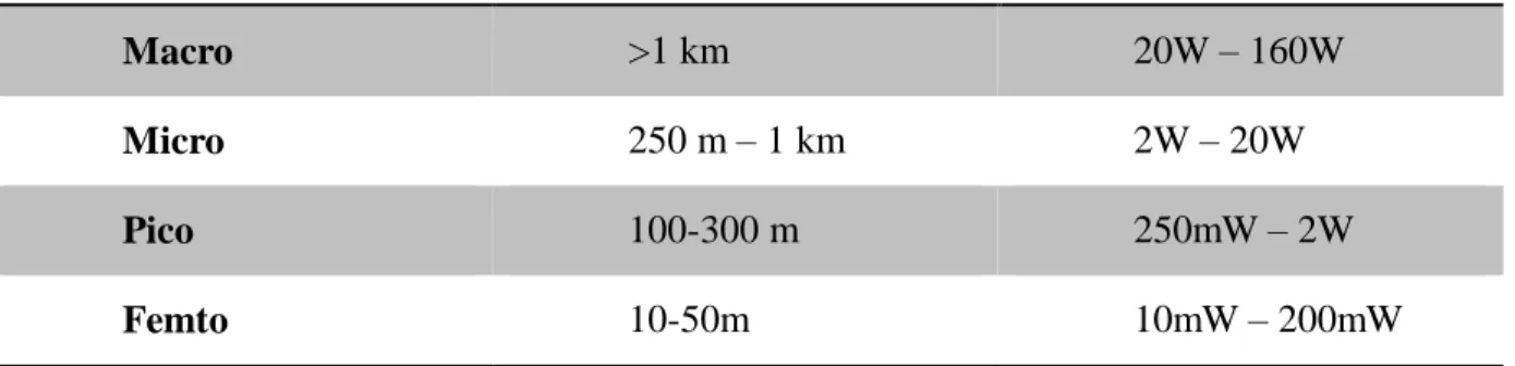
Table 2.1: Power and coverage comparison of Base station types
Cell Type Typical Coverage radius Transmit Power Range
Macro >1 km 20W – 160W
Micro 250 m – 1 km 2W – 20W
Pico 100-300 m 250mW – 2W
The summary of power and coverage analysis of the different type of base stations presently in existence are given in Table 2.1 while the differences between the Pico-cell and Femto-cells are clearly illustrated in Table 2.2
Table 2.2: Structural comparison of Pico-cell and Femto-cell
Parameters Pico-cell Femto-cell
Installed by Network operator By the end-user
Connection to the Core network
Coaxial, Fibre Optic ADSL, Cable
Price Cheap Very cheap
Capacity 10-50 users 3-5
Coverage range <100m <30m
Femto-cells are deployed in an ad-hoc manner as users can buy and install them anywhere they desire. A single user or home can have more than one, depending on the size of the home and the number of occupants or subscribers that will be connecting to the Femto-cell infrastructure. These attributes of Femto-cells make it important for some special design considerations to be taken into account before their widespread deployment. Furthermore, since Femto-cells will not be managed by the CSP on whose infrastructure they will be attached, capabilities such as self-configuration, self-optimization and self-healing are needed to be built into each of the Femto-cells and their respective sub-network. These capabilities, when incorporated enable the network to be a self-organising network (SON). A self-organising network requires minimal human involvement for seamless operation. Processes such as planning, configuration and optimization
2.4
Self-Configuration
Due to the plug and play nature of Femto-cells and the fact that they are user-commissioned, it is very important that once switched on, the Femto-cells are able to communicate and integrate into the existing network. The Femto-cells set up their software and other parameters such as neighbours list, handover configuration, pilot power and attached subscribers. All these must be done with minimal interruption to existing base stations. Femto-cells that are already switched on can also run their self-configuration phase algorithms if new base-stations or features are detected in the network [17].
2.5
Self-Optimization
Network measurements are carried out periodically by each Femto-cell and are processed. Femto-cells use these measurements to modify their algorithms and adjust parameters that are variable to suit changing conditions of their environment. Examples of metrics that can be optimized are the outage probability, channel capacity and the level of interference mitigation that can be provided.
2.6
Self-Healing
This involves capabilities built into Femto-cells to enable them recover from situations of coverage loss, loss of connectivity to the core network and capacity failure. These could be due to radio board failure, channel processing implementation error, misconfiguration, power outage and back-haul connectivity failure [18]. Outage detection is a self-healing function that determines cells that are in outage conditions. After a downed Femto-cell has been correctly detected, the outage compensation procedure is initiated to reduce the effect of coverage loss and throughput reduction. Compensation procedure encompasses modification of parameters such as transmission power and channels allocated to nearby Femto-cells. Self-healing activities are aimed at reducing the impact of outages on the subscribers through rapid tuning of parameters of Macro and Femto-base stations present in the network.
2.7
Femto-cells Operating Modes
Femto-cells will operate in the open subscribers group (OSG) access mode or the close subscribers group (CSG) access mode. With the OSG access mode, any user that belongs to the network is allowed to connect to a Femto-cell if they receive an SINR from the Femto-cell that is higher than that from the Macro-cell to which they were initially attached. For the CSG access mode, only users belonging to a subscribers’ list are allowed to be attached to a Femto-cell. CSG is the common mode of deployment since Femto-cells are user-deployed. OSG mode is useful when Femto-cells are deployed by a CSP itself for coverage in areas such as airports, stadia or street corners where Pico-cells can also be used.
CSG mode of deployment contributes more interference because User Equipment (UE) that is far away from their attached Macro-cells radiate at higher power levels, but if connected to a nearby Femto-cell, the power needed is reduced. A unit of Macro User Equipment (MUE) radiating at an increased power level causes severe interference to nearby Femto-cell base stations if they share the same set of resource blocks. The type of access mode proposed to mitigate this challenge is the Hybrid access mode.
The Hybrid access mode is similar to the CSG with the difference that some UE not belonging to the subscribers’ list of a particular Femto-cell can still connect to it. They are given some level of service but they will not be able to get any preferential treatment and will be charged higher for any service they use as compared to UE belonging to the subscribers list. This type of deployment is more likely to be found in relatively large office buildings and it is important for subscribers to know the different charging policies that apply [19]. The CSG access mode was assumed in the investigation that was conducted in this dissertation.
Good signal quality for indoor subscribers leading to improvement in call (voice, video or data) qualities i.e. the Femto-cell provides all-time 5-bar coverage.
Reduction in the power usage of terminal equipment in indoor areas as lesser level of radiation is needed because of proximity to the indoor cell; this enhances the battery life of an UE.
Indoor traffics are off-loaded to Femto-cells and this ensures that fewer numbers of Macro-cells are needed in a geographical area. This reduces the capital expenditure (CAPEX) for the CSP and releases the resources that can then be used to serve the outdoor users better.
Simplification of site survey and planning process for network roll out or optimization activities.
Deploying Femto-cells reduces a CSP’s Churn rate. The Churn rate is defined as the percentage of subscribers who stopped using an operator’s service for one reason or the other at a given period. It has been established through surveys that poor indoor coverage is the major churn-causing factor for CSPs.
Femto-cells create more demand for data-services thus increasing the revenue for the CSP. It also helps the development of add-on services such as Femto-zone or home zone where subscribers can get added bundle packages for voice and data at a lower cost.
2.9
LTE Femto-Cell Physical Layer Structure
2.9.1
OFDM/OFDMA
Wireless channels are characterized by frequency selective fading impairments. This causes different channels to experience different levels of fading depending on the channel’s frequency. Frequency selectivity results from the phenomenon of multipath signal propagation that characterizes indoor and urban environments. Radio access technologies using wideband signals such as the 3G UMTS-CDMA systems can suffer extensive distortion. This makes signal recovery at the receiving end difficult and leads to overall network performance degradation.
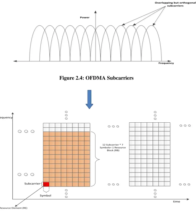
Narrowband signals as illustrated in Fig. 2.4 provide better resistance against frequency selectivity and this gives rise to multicarrier modulation technologies such as orthogonal frequency division multiplexing (OFDM). In OFDM, each subcarrier is orthogonal to each other; hence, the overlapping of subcarriers without causing inter-symbol interference (ISI) is made possible. This makes it more spectrally efficient when compared to FDMA as more symbols can be packed into a given bandwidth.
The analysis done in this thesis is focused on interference coordination and mitigation for Macro-cell networks overlaid with Femto-cells in LTE-A networks which meets the requirements of the ITU-R’s IMT-Advanced specifications for 4G networks. On the downlink, LTE-A builds on the framework of ordinary LTE and it sits on the Orthogonal Frequency Division Multiple Access (OFDMA) technique as its physical layer technology. The Single Carrier Frequency Division Multiple Access (SC-FDMA) is used on the uplink because it is cost-efficient and conserves power. The next section gives a brief detail of OFDMA as it applies to LTE with emphasis on resource allocation.
2.9.2
OFDMA Resource Grid Structure
LTE supports both frequency division duplexing (FDD) and time division duplexing (TDD).
The basic time unit is Ts and it is defined as seconds or about 32.6
nanoseconds.
A single frame in LTE has 10ms time duration (Fig. 2.6). For FDD, the whole frame is dedicated to either downlink or uplink. The frame is shared between uplink and downlink in the case of TDD.
The smallest modulation element in LTE is called a Resource Element (RE) and it is a 15 KHz subcarrier (frequency axis) by one symbol (time axis). These resource elements are aggregated into resource blocks (RBs). Twelve consecutive sub-carriers in the frequency domain and seven symbols in the time domain form a single resource block. LTE supports multiple modulation schemes such as QPSK, 16-QAM, 64-QAM. These with other parameters such as coding rate and the channel quality indicator (CQI) are used to determine the number of bits that makes up a symbol, which is modulated onto a single RE during a transmission stream. This is a concept referred to as adaptive bit loading [20]. The adaptive bit-loading scheme ensures that the better the channel condition, the higher the radio access bearer (RAB) or modulation order used.
As a result, data rate delivered to users with OFDMA can be diverse as there are different combinations of parameters with a high degree of freedom available for system design. This makes finding an optimal operating condition of the network challenging and often times, the concept of optimality can be subjective and largely determined by the type of service a CSP wants to deliver to its subscribers.
Power
Frequency
Overlapping but orthogonal subcarriers
Figure 2.4: OFDMA Subcarriers
Symbol Subcarrier
12 Subcarrier * 7 Symbols= 1 Resource
Block (RB)
A Resource Element (RE)
frequency
time
LTE-A adds capabilities such as Multiple Input Multiple Output (MIMO) antennas to provide spatial diversity or spatial multiplexing in order to enhance performance and carrier aggregation (CA) techniques.
Interference will result if two different base stations, either Macro or Femto schedule a resource block to be used for data transmission between their respective users at the same time and frequency.
2.10
LTE Femto-Cell Logical Architectures
The Third Generation Partnership Project 3GGP workgroup specified three architectural variants for the deployment of Femto-cells in a geographical environment [21] [22]. Since a CSP that wants to deploy Femto-cells already has an existing infrastructure in place, it is important to consider an architecture that is not intrusive and cumbersome to implement. The architecture also has to be scalable and easy to evolve in case of future adjustments. The differences in the variants lie in how the Home enhanced Node B (HeNB) is connected to the Evolved Packet Core of the LTE network on both the control and user plane.
UE HeNB HeNBGW MME S-GW HSS CSG List Srv S1 S6a LTE-Uu S1-MME S1-U S11 VPLMN C1 (OMA DM /OTA) HPLMN
Figure 2.7: LTE Femto-cell Logical architecture (Variant 1) [22]
the network on both the user plane (S1-U) and the control plane (S1-MME) before sending the traffic to the core of the network. The advantage of this variant is that the increase in the number of deployed Femto-cells does not lead to a corresponding increase in the control plane signalling between the access and the core network. In the situation of massive HeNB failure that can occur due to power failure, the Mobile Management Entity (MME) in the core will not be overloaded when the HeNBs come back online. Furthermore, this approach provides better network security as the IP addresses of the core network elements are not revealed to the UE. Useful information regarding interference coordination or mitigation can also be exchanged over the S1-MME interface between the HeNBs and the MeNB. The variant 2 depicted in Fig. 2.8 removes the HeNB-GW present in variant one and favours direct connectivity of the HeNBs to the core of the CSP. With this architecture, the MeNBs and the HeNBs are connected to the core with similar technique. Its benefit is that there are less failure points in the system and it does not include an additional single point of failure.
UE HeNB MME S-GW LTE-Uu S1-MME S1-U S11 HSS S6a CSG List Srv C1 (OMA DM /OTA) VPLMN HPLMN
Figure 2.8: Femto-cell Logical architecture (Variant 2) [22]
In order to solve the problem of possible control plane overload of the MME in variant 2, the HeNB-GW was re-introduced in variant 3 similar to variant 1 but it only terminates control plane signalling from the HeNBs. The user plane is directly connected to the S-GW at the core of the CSP. The variant 3 is depicted in Fig. 2.9, with this architecture; increasing number of HeNBs does not lead to SCTP overload towards the MME.
UE S1-MME S1-U LTE-Uu S1-MME S11 HSS S6a HeNB HeNB GW S-GW MME CSG List Srv C1 (OMA DM /OTA) VPLMN HPLMN
Figure 2.9: Femto-cell architecture (Variant 3) [22]
The demerits associated with the variant 3 include the possibility of an overload situation in the S-GW when the number of HeNBs deployed in the network increases. In addition, the presence of the HeNB-GW on the control plane reduces redundancy and load-balancing possibility as the HeNBs can only connect to one HeNB-GW at a time.
In order to deploy a convenient interference mitigation or coordination scheme, it is important to understand the type of Femto-cell logical architecture that will be employed in the network. This ensures that suitable design approach as to the exchange of control signals between the network entities is taken. Further extension in connectivity between HeNB and MeNB over the X2 interface has also been proposed by the related SDOs[23].
2.11
Chapter Summary
systems and the benefits of using Femto-cells have also been highlighted. The associated problem of Femto-cells interference has been discussed. In the next chapter, the extent of performance degradation, which can result when Femto-cells are deployed in the network without proper interference mitigation, will be presented using a standardized LTE simulator. Afterwards, a survey of interference mitigation schemes in literature will also be presented.
Chapter 3
3
Literature Review
3.1
Chapter Introduction
In this chapter, the Vienna LTE simulator was used to analyse the degrading impact of interference on channel capacity when Femto-cells are deployed over a Macro-cell network to buttress the need for interference mitigation techniques in modern wireless communication networks. The various categories of interference in multi-tier heterogeneous radio access networks are given with emphasis on Macro-cell overlaid with Femto-cells. Broad related works will then be discussed with more attention on the efforts in literature that were directed at interference coordination and avoidance techniques such as Fractional Frequency Reuse (FFR). The shortcomings discovered in existing works are noted and the proposed solution is clearly highlighted.
3.2
The Vienna LTE Simulator
In order to meet the requirements and specification of the 3GPP workgroup for LTE and LTE-Advanced, development of new technologies and modifications to existing ones are needed to be implemented on the different generic layers that constitute a digital communication system. Research efforts directed towards developing the technologies and investigating their performance under different conditions are usually difficult to synchronize and reproduce among various industrial and academic laboratories. This is due to lack of full disclosure of the nature of input data, assumptions made, values of system parameters used etc. This can make the reproduction of results reported in academic papers challenging for other researchers willing to continue from where a previous investigative effort stopped.
The Vienna LTE simulator was developed by authors of [24], [25] as a platform that aids the alignment of research efforts directed at achieving the LTE specifications as given by the
the results of analysis that can easily be reproduced and improved. This software package has link level and system level simulators as separate entities built on the MATLAB platform, and employs the Object Oriented Programming (OOP) development technique. The Vienna LTE simulator was used in this work instead of OPNET, OMNET or NS-3 because it was specifically designed for LTE and LTE-Advanced simulation purposes. Unlike the other simulators, which can be used for testing generic network communication protocols and different standards, the Vienna simulator is streamlined only for LTE related research purposes.
Link level simulations are used to investigate the performance of channel estimation techniques, tracking and prediction algorithms, Multiple Input Multiple Output (MIMO) gains, adaptive modulation and coding (AMC) including its feedback [24]. Other features such as the receiver structure with reduced complexity, channel modelling, channel encoding and decoding are also implementable using the Vienna LTE link level simulator.
System Level simulations on the other hand is useful for testing schemes that are network related such as resource allocation and scheduling, interference management, network planning and optimization, call admission control and multi-user handling [24]. Results of experiments from the Link level simulator such as the values of the received signal strength under different network link conditions, which are mapped to produce the channel quality indicator (CQI), are used as a benchmark for the system level simulator to ensure uniformity and reproducibility of results in both set of simulators.
In this section, the system level simulator was used to investigate the performance of a mobile network that initially consisted of only Macro-cells. Femto-cells were then overlaid on the Macro-cell and the channel capacity metric of the network was checked and compared with the result achieved when only the Macro-cells were deployed. Minimal interference mitigation was implemented and this was done to demonstrate and ascertain the impact of the deployment of
3.2.1
Scenario 1: Macro-cell only deployment
The Vienna LTE simulator was installed in MATLAB (R2009b) and a Macro-cell only network as shown in Fig. 3.1 was generated. The codes used for generating this network are given in appendix A. The operating frequency was set at 2 GHz with a bandwidth of 5 MHz, which corresponds to 25 resource blocks (RB). A MIMO antenna configuration was implemented. A 19-cell layout was considered, with MUE uniformly and randomly distributed all over the coverage area. The throughput statistics are taken from users in the first and the second tier of the network. The cell with cell ID 11 is the central MeNB while cells with IDs 12, 16, 10, 5, 6, and 7 make up the second tier as can be seen in Fig. 3.1.
Figure 3.1: Macro-cell only scenario
3.2.2
Scenario 2: Femto-cells overlaid on Macro-cell.
situation. In order to make objective comparisons between the two sets of deployment scenarios, the parameters given in appendix A were kept constant for both sets of simulation run. The Femto-cells were deployed randomly in the region of interest and no interference mitigation technique was implemented. The available bandwidth was shared between the Femto-cells and the Macro-cells. Maximum of two users were attached to each of the cells and each Femto-cell antenna radiates in an omnidirectional pattern. The units of UE were kept static during the simulation run and the statistics were taken over a transmission time interval (TTI) of ten.
The region of interest (ROI) was kept constant in both scenarios but it is more difficult to control radiation pattern of the Femto-cells due to their Ad-hoc mode of deployment. This makes the coverage area in Fig. 3.2 slightly larger than that of the Macro-cell only scenario.
The average UE throughput for all the users in the network was employed as the main performance metric. This is because of its importance in determining the quality of experience of the users attached to a network operator and its reliance on the SINR experienced by each user.
Figure 3.4: Throughput for Macro-cell overlaid with Femto-cells Scenario
Fig.3.3 shows the average throughput in Mbps that is achieved by the UE equipment in a single tier network that consists only of Macro-cells as shown in Fig. 3.1. It can be deduced that the average throughput of the units of UE ranges from 0 Mbps to 15 Mbps based on the channel quality between each of the user and their attached Macro-cell. Considering the Macro-cell overlaid with Femto-cells throughput graph in Fig. 3.4, there was a decrease in the achieved average throughput of the users (ranging from 0 to about 5 Mbps). From this, it can be seen that while Femto-cells offer a means of improving signal coverage and allowing more users connection to the network, sub-optimal overall network performance can result without the implementation of proper interference mitigation schemes. The outcome of this analysis using the Vienna LTE simulator supports the findings of earlier research efforts in [26] and [27] into the study of the performance of multi-tier networks where other analytical platforms were used.
3.3 Interference Categorization
In Multi-tier cellular networks, the presence of more than a single network infrastructure or RAT that backhauls user data traffic to the core of the network operator leads to two different interference scenarios, which are the Cross-tier and Co-tier interference. The categorization is important in order to deploy the most effective interference mitigation approach that best suits the interference scenario. This is because there exists a relatively vast degrees of freedom and parameters that need to be optimized depending on what is required of the network performance which can either be the maximization of the area spectral efficiency (ASE), or the maximization of achievable throughput in each tier of the network [28].
3.3.1 Cross-Tier Interference
This interference occurs among network entities that belong to different tiers or layers (or cell-types located in the same geographical region) of a network. The aggressor, which is the entity causing the interference belongs to a different layer of the network with respect to the victim, which is the entity that suffers from the interference contributed by the aggressor. The level of cross-tier interference contributed depends on the density of the aggressors in a geographical region and their transmit power on the shared or adjacent spectrum resource [14].
3.3.2 Co-Tier Interference
Co-tier interference on the other hand occurs between network elements that belong to the same layer or tier of the network i.e. interference resulting from the transmission and reception activities of both the base stations and mobile user terminals connected to the same infrastructure type (e.g. Macro-cells or cells) of a network operator in a given geographical area. Femto-cell to Femto-Femto-cell co-layer interference can occur due to low isolation between houses or apartments in which the Femto-cells are deployed [14] though the generally low transmission power of Femto-cells and the high likelihood of attenuation due to walls reduces the intensity of the Femto-cell co-tier interference.
A summary of the different interference situations that can occur in a two-tier network comprising of Macro-cells and Femto-cells is given in Table 3.1
Table 3.1: Interference Scenarios
3.4 Interference Management in Heterogeneous Networks
Interference management and mitigation methods can be broadly categorized into interference cancellation and interference avoidance schemes (Fig. 3.5).
Aggressors Victims
Femto BS Macro BS Femto UE Macro UE
Femto BS N/A N/A Co-Tier
Downlink
Cross-Tier Uplink
Macro BS N/A N/A Cross-Tier
Uplink N/A Femto UE Co-Tier Downlink Cross-Tier Downlink N/A N/A Macro UE Cross-Tier Downlink Co-Tier Downlink N/A N/A
Interference cancellation schemes operate in the spatial domain and employ advance signal processing techniques to cancel out the interfering signal from the desired signal. Interference avoidance on the other hand uses orthogonal transmission either in the frequency domain or in time domain to mitigate interference. Also, power control approach to interference avoidance ensures that the desired signal’s transmission power is increased while that of the interfering signal is reduced using complex algorithms. Further overview of these techniques is presented in succeeding sections.
3.4.1 Clustering of Femto-cells
This form of interference mitigation in Multi-tier heterogeneous networks involves the grouping of Femto-cells located in a geographical region together under a control node which can be a Femto-cell System Controller (FSC) as proposed in[29]. The FSC is attached to all the MeNBs that comprise the network of the mobile operator. Each FSC is connected to the HeNBs in the network and it is able to access their location via information exchange on the back-haul links. This approach is suitable to CSPs that possess the infrastructure to provide both fixed and mobile services. The spectrum is divided into two; one portion is dedicated to Macro-cell communication while the other is shared between the Macro-cell and the Femto-cells. The dedicated portion helps to ensure that the downlink (cross-tier) interference is totally mitigated and used for communication between the MeNB and MUEs that are close to the Femto-cells. A clustering algorithm is used to determine the proportion of the spectrum resource to be shared between the two-tiers and this partially depends on the density of the Femto-cells in the network. The clustering algorithm calculates the threshold distance which is the distance below which Femto-cells are allocated to different clusters in order to prevent severe co-tier and cross-tier interference. Simulation result of this implementation shows that high spectral efficiency is achieved with the probability of cross-tier spectrum reuse as high as 97.4%. This solves the UE downlink dead-zone problem considerably.
The Femto-cell coordinator in a group of other Femto-cells is simply referred to as the header in the proposition made by H. Widiarti et al. in [30]. The scheme was based on the IEEE
layer technique of OFDMA is used by both framework. The Low Duty Operation (LDO) mode specified in IEEE 802.16m is exploited to implement a design that mitigates cross-tier interference.
The idea is to reduce the number of unnecessary available interval (AI) that is transmitted by the HeNBs on the air interface when no UE is attached. The HeNB can switch to the LDO mode when there is no HUE attached but from time to time, it switches to AI in order to determine if an HUE has entered its coverage to commence synchronization. The concept of clustering of Femto-cells is used to group ‘member’ HeNBs under a ‘leader’ HeNB.
When no UE is attached to the member HeNBs, it is only the leader HeNB that alternates between the AI and UnAvailable Interval (UAI) to sense if a HUE has entered the coverage region of any member HeNB that belongs to its group. With this procedure, a HeNB will receive the preamble signal from the leading HeNB. If the received preamble signal power is above a particular pre-defined threshold, then the HeNB connects to this leading HeNB’s cluster but if it is below the pre-defined threshold and there is no preamble signal above the threshold from another leading HeNB, then the new HeNB forms a new cluster. The HeNB will then be the leader of the newly formed cluster.
The advantages of this technique include mitigation of cross-tier interference and reduction in the energy utilised by the HeNBs. The more the number of UAI in a LDC, the more the interference reduction time (IRT), the lesser the intensity of cross-tier interference and the lesser the energy consumed by the HeNBs in the network. Numerical and simulation analysis presented by the authors showed a gain in IRT and energy saving of up to ninety per cent.
Another implementation that incorporates the concept of clustering was put forward in [31]. Here, to replace the FSC of [29] and leader HeNB of [30], Distributed Antenna System
![Figure 1.2: Compositional Structure of Heterogeneous Networks [4]](https://thumb-us.123doks.com/thumbv2/123dok_us/10175189.2919828/22.918.125.795.107.624/figure-compositional-structure-heterogeneous-networks.webp)
![Figure 1.3: Multi-tier Network Concept [4]](https://thumb-us.123doks.com/thumbv2/123dok_us/10175189.2919828/23.918.136.782.108.440/figure-multi-tier-network-concept.webp)
![Figure 1.4: Global mobile traffic forecast (Cisco VNI) [8]](https://thumb-us.123doks.com/thumbv2/123dok_us/10175189.2919828/24.918.213.768.321.593/figure-global-mobile-traffic-forecast-cisco-vni.webp)
![Figure 2.7: LTE Femto-cell Logical architecture (Variant 1) [22]](https://thumb-us.123doks.com/thumbv2/123dok_us/10175189.2919828/42.918.199.769.690.939/figure-lte-femto-cell-logical-architecture-variant.webp)
![Figure 2.8: Femto-cell Logical architecture (Variant 2) [22]](https://thumb-us.123doks.com/thumbv2/123dok_us/10175189.2919828/43.918.197.770.543.816/figure-femto-cell-logical-architecture-variant.webp)
![Figure 2.9: Femto-cell architecture (Variant 3) [22]](https://thumb-us.123doks.com/thumbv2/123dok_us/10175189.2919828/44.918.226.750.287.556/figure-femto-cell-architecture-variant.webp)

