Humanrobot cocarrying using visual and force sensing
Article (Accepted Version)
http://sro.sussex.ac.uk
Yu, Xinbo, He, Wei, Li, Qing, Li, Yanan and Li, Bin (2020) Human-robot co-carrying using visual
and force sensing. IEEE Transactions on Industrial Electronics. ISSN 0278-0046 (Accepted)
This version is available from Sussex Research Online: http://sro.sussex.ac.uk/id/eprint/92926/
This document is made available in accordance with publisher policies and may differ from the
published version or from the version of record. If you wish to cite this item you are advised to
consult the publisher’s version. Please see the URL above for details on accessing the published
version.
Copyright and reuse:
Sussex Research Online is a digital repository of the research output of the University.
Copyright and all moral rights to the version of the paper presented here belong to the individual
author(s) and/or other copyright owners. To the extent reasonable and practicable, the material
made available in SRO has been checked for eligibility before being made available.
Copies of full text items generally can be reproduced, displayed or performed and given to third
parties in any format or medium for personal research or study, educational, or not-for-profit
purposes without prior permission or charge, provided that the authors, title and full bibliographic
details are credited, a hyperlink and/or URL is given for the original metadata page and the
content is not changed in any way.
Human-Robot Co-Carrying Using Visual and Force
Sensing
Xinbo Yu,
Member, IEEE,
Wei He,
Senior Member, IEEE,
Qing Li, Yanan Li,
Member, IEEE, Bin Li
Abstract—In this paper, we propose a hybrid framework using visual and force sensing for human-robot co-carrying tasks. Visual sensing is utilized to obtain human motion and an observer is designed for estimating control input of human, which generates robot’s desired motion towards human’s in-tended motion. An adaptive impedance-based control strategy is proposed for trajectory tracking with neural networks (NNs) used to compensate for uncertainties in robot’s dynamics. Motion synchronization is achieved and this approach yields a stable and efficient interaction behavior between human and robot, decreases human control effort and avoids interference to human during the interaction. The proposed framework is validated by a co-carrying task in simulations and experiments.
Index Terms—Human-robot collaboration, Motion synchro-nization, Observer, Neural networks, Visual and force sensing.
I. INTRODUCTION
Physical interaction of human and robot (pHRI) in shared environments and joint tasks poses many challenges [1]. There exist extensive applications of pHRI found in service and industrial areas including assembly, rehabilitation [2] and so on [3]. Co-carrying tasks, which rely on complementary advantages of human and robot, cannot be accomplished individually by a single human or robot. Coupled relationships between robot, transported object and human bring difficulties in analyzing behaviours of both human and robot. In this paper, the focus of interest is using vision and force sensing together to enable human and robot collaboratively to perform a co-carrying task. For this purpose, robot should have the following abilities:
1) measure human motion and estimate human motion
intentionfor achieving motion synchronization;
2) measure external force on robot gripper and regulate interaction force for achieving safe interaction;
3) carry out human-in-the-loop control strategy considering system uncertainties.
This work was supported in part by the National Natural Science Foundation of China under Grant 61933001, 61621063, in part by Beijing Top Discipline for Artificial Intelligent Science and Engineering, University Science and Technology Beijing, and in part by the Fundamental Research Funds for the China Central Universities of USTB under Grant FRF-TP-19-001C2.
X. Yu is working with the Institute of Artificial Intelligence, University of Science and Technology Beijing, Beijing 100083, China. W. He and B. Li are with the School of Automation and Electrical Engineering, Institute of Artificial Intelligence, University of Science and Technology Beijing, Beijing 100083, China. Q. Li is working with the School of Automation and Electrical Engineering, University of Science and Technology Beijing, Beijing 100083, China. Y. Li is with the Department of Engineering and Design, University of Sussex, Brighton, BN1 9RH, UK.
The corresponding author is W. He, Email: [email protected].
How to understand human sensorimotor behavior is a key for robot to achieve compliant interaction in pHRI. Robot can take
a “follower” role in pHRI without knowing human motion
in-tention. However, passive control of robot may disturb human behaviors, affect human trust or bring human more burden in co-transporting tasks. In [4], online neural networks are employed to estimate human motion intention which is defined as the human’s desired trajectory, and less human efforts are required with the proposed method. In [5], human motion intention is estimated by observing robot control effort without force sensors. A switching control scheme is developed that changes between impedance control and interaction control. In
[6], human motion intention is deemed as the current human
motion, without considering the future motion estimation.
Human muscle activity measurements encode the information about human motion, and provide robot with online feedback information. Based on this idea, human motion intention also can be defined as continuously time-varying force or torque [7]. In our paper, we regard human motion intention as moving target position which leads to a continuous trajectory. A related work can be found in [8], which can provide a desired trajectory based on the interaction force in pHRI without constant human guidance and results in reduction in human control effort. Most of these studies in the field of motion intention estimation have only focused on direct interaction rather than indirect pHRI, i.e. through an object in co-carrying tasks. Complicated coupled relationships between human, object and robot bring more difficulties in estimating human motion intention. Therefore one purpose of our work is to estimate human motion intention in co-carrying tasks with indirect interaction.
Controller design in pHRI has received considerable at-tentions in recent years [9]–[16]. A remarkable issue is that accurate robot’s dynamics are extremely difficult to obtain from the engineering point of view [17]. However, it is critical to acquire sufficient information about robot’s dynamics for achieving precise torque control [18]–[21]. In [22], an adaptive impedance control of dual-arm robots is proposed where neural networks (NNs) are utilized to compensate for uncertain dynamics. In [23], human-like adaptive controller is proposed for compensating for disturbance and dynamics without force sensing, and it is derived from minimizing control effort and error. In conclusion, uncertainty compensation is an important component in controller design [24]–[29], and also plays a key role in pHRI [30].
Joint tasks have been extensively studied in the field of pHRI [31]. In [32], authors design a control strategy which allows a humanoid robot to perform a complex co-carrying
task with human, and robot can guess human motion to proactively participate to the task. Human stiffness estimation is also an increasingly important area in co-carrying tasks. In [33], weight least-squares estimation is employed to estimate virtual stiffness, which is included in the complete set of task-parameterized Gaussian mixture model. This model can be used for impedance-based behaviors transfer. A related work can be found in [34], where authors proposed an approach considering probabilistic stiffness estimation, and encoding robot behavior in the task involving physical contact with the human. In [35], unknown grasp pose of human is identified, and online estimation of relative kinematics is derived by least square method. In the subsequent works, the authors consider that the object dynamics are unknown in co-transporting tasks, so they propose an identification strategy of object dynamics in the condition that inputs satisfy persistence of excitation (PE) [36]. However, most of research relies on force information in human control input. In [37], a hybrid controller combining visual servoing and impedance controller is considered in the task of joint carrying and a “ball-on-plate” system is employed to validate the effectiveness of this controller. In [38], an observer is designed to estimate control input of human, and motion synchronization in a direct pHRI scenario is achieved without requiring force sensory information at the interaction point. Inspired by the aforementioned works [37] and [38], visual servoing and observer are employed in our controller design. Visual servoing is utilized to obtain human motion and observer is used in estimating control input of human. A hybrid framework including visual and force sensing is proposed for human-robot co-carrying tasks. In [39], a companion robot is designed to switch between the visual servoing and force servoing modes, different from our framework using visual and force sensing to estimate the human motion intention. In [40], [41], robots learn the teaching-learning-collaboration model and predict human motion through learning by demonstrations or using historical data for training, while our method requires neither of them. Based on previous discussions, we highlight our contributions as follows:
1) A hybrid framework using visual and force sensing is proposed for human-robot co-carrying tasks, enabling the robot to proactively follow its human partner and reduce their control effort;
2) A force observer is designed to estimate human force without using the force sensor, and human motion in-tention is obtained by minimizing the estimated force.
The proposed framework includes both visual and force sensing, and a controller combining visual servoing control and impedance control is designed, so we call it “hybrid”.
The rest of the paper is presented as follows: Section II presents robot and object dynamics, and control inputs of human and robot are analyzed; Section III introduces the proposed method; Section IV and Section V evaluate its performance by simulations and experiments; Section VI and Section VII conclude this work and discuss future works.
II. PROBLEMFORMULATION
A. System description
We consider a co-carrying task where human and robot transport a rigid object as depicted in Fig. 1. All vectors and matrices are defined in the fixed coordinate frame of robot
{R}, of which the origin is at the robot’s mass center.
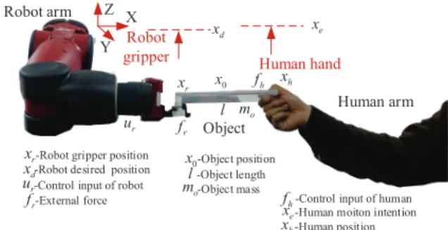
Human arm Robot arm Human hand Robot gripper Object h f xh 0 x r x r f l mo e x d x
-Control input of human -Human moiton intention -Human position -Object position
-Object length -Object mass -Robot gripper position
-Robot desired position -Control input of robot -External force r f e x h x 0 x l o m r x d x r u r u h f Z Y X
Fig. 1: Human-robot co-carrying task.
The dynamics of annlink robot is given by:
Mr(xr)¨xr+Cr(xr,x˙r) ˙xr+Gr(xr) =ur−fr (1)
where Mr(xr) ∈ Rn×n, Cr(xr,x˙r) ∈ Rn×n, Gr(xr) ∈ Rn
denote mass matrix, Coriolis and centripetal matrix, gravity
vector in robot’s dynamics, respectively; xr,x˙r,¨xr ∈ Rn
denote position, velocity and acceleration vectors of robot
gripper, respectively; fr ∈ Rn denotes external force on the
robot measured by a force sensor or calculated based on torque
sensors, and ur ∈ Rn×n denotes the control input of robot.
Similarly, the dynamics of anndimension transported object
can be described as follows:
Mo(xo)¨xo+Co(xo,x˙o) ˙xo+Go(xo) =fh+fr (2)
where Mo(xo) ∈Rn×n, Co(xo,x˙o) ∈ Rn×n andGo(xo) ∈
Rn denote mass matrix, Coriolis and centripetal matrix and
gravity vector in object’s dynamics, respectively; and xo,x˙o
andx¨o∈Rndenote position, velocity and acceleration vectors
of object’s mass center;fh∈Rn denotes the external force at
the grasp point onto the transported object.
B. Control input
1) Control input of human: In this work, control input of
human is defined as fh in object dynamics model (2). We
describe it as a simplified stiffness model as follows:
fh=−Kh(xh−xe) (3)
where Kh ∈ Rn×n denotes the stiffness matrix of human
arm, xh ∈ Rn denotes human position, i.e., position vector
of human hand which contacts with the transported object,
xe∈Rn denotes human motion intention.
We can see that if robot knows human motion intentionxe
in real time and moves towards the desired motionxd
accord-ing toxe, the co-carrying task can be performed successfully
andactively. According to (3), iffh,xh andKh are obtained,
xe can be calculated. Before we design a tracking control
algorithm for robot, some issues should be addressed about
1) In a scenario where it is infeasible to directly measure
human force, how we can obtain fh should be
consid-ered;
2) There are differences between xh and xr when human
and robot collaborate to transport the object, so how we
obtainxh should be addressed;
3) Without knowledge of human stiffness Kh, an effective
estimation method to obtainxe should be proposed.
2) Control input of robot: Different from the definition of
control input of human, control input of robot is ur rather
than the external force fr on the object. In view of control
objective, the control input of robot is designed as follows:
ur=urf+urb+uri (4)
where urf denotes the feedforward input for compensating
for robot’s dynamics, urb denotes the feedback input for
tracking the desired trajectory xd, and uri denotes the input
for compensating for the interaction force. We can design corresponding inputs as follows:
urf =Mr(xr)¨xd+Cr(xr,x˙r) ˙xd+Gr(xr)
urb=−KP(xr−xd)−KD( ˙xr−x˙d) +KQsgn( ˙xr−x˙d)
uri=fr+ (( ˙xr−x˙d)T)+( ˙xh−x˙d) ˆfh (5)
whereKP denotes the proportional gain matrix, andKD
de-notes the differential gain matrix, which can be interpreted as
stiffness and damping matrices in impedance control.KQ will
be explained subsequently in stability analysis.(( ˙xr−x˙d)T)+
denotes the Moore-Penrose inverse of ( ˙xr−x˙d)T, and sgn(·)
returns a vector with the signs of the corresponding elements
of the vector (·). To address uncertainties in robot’s dynamics,
neural networks (NNs) are employed to compensate for them. And we design the weight adaptive law as follows:
˙ˆ
θi=−Γi[Si(Zi)( ˙xri−x˙di) +σiθˆi], i= 1,2, ..., n (6)
where θˆi denotes weight estimates of NN, Γi = ΓTi denotes
a positive definite matrix and σi denotes small positive
con-stants.Zi=[xTr,x˙Tr,x˙Td,x¨Td] denotes the input of NN,Si(Zi)
denotes basis functions, and θˆTS(Z) is used to estimate
θ∗TS(Z)as below
θ∗TS(Z) = (Mr(xr)¨xd+Cr(xr,x˙r) ˙xd+Gr(xr))−ε(Z)
(7)
where θ∗i denotes actual weight of NN, and the estimation
error vector ε(Z) stays in bounds over the compact set Ωε,
∀Z∈Ωε,||ε(Z)||<ε, with¯ ε¯as a positive constant. Then we
develop adaptive NN as follows:
urN N = ˆθTS(Z)−KP(xr−xd)−KD( ˙xr−x˙d) +fr
+KQsgn( ˙xr−x˙d) + (( ˙xr−x˙d)T)+( ˙xh−x˙d) ˆfh
(8) Substituting (8) to (1), we can obtain the closed-loop error dynamics:
Mr(xr)¨e+ (Cr(xr,x˙r) +KD) ˙e+KPe=−θ∗TS(Z)−
ε(Z) + ˆθTS(Z) +KQsgn(e) + ( ˙eT)+( ˙xh−x˙d) ˆfh (9)
wheree∈Rn denotes the tracking error betweenx
r andxd.
In (8), if we setxd asxe, which means that robot is aware of
human motion intention, robot can conductsynchronous and
activecollaboration with human partner in the co-transporting
task. If we want to updatexdrelative toxe, we need to obtain
human motionxh by visual sensing according to analysis in
Section III.
III. SENSING,OBSERVER DESIGN AND HUMAN MOTION
INTENTION ESTIMATION
A. Visual sensing and force sensing
1) Visual sensing: We use a visual sensor to obtain human
motion xh in our work. xh obtained by the visual sensor
should be transformed into robot coordinate {R} for further
controller design. Calibration systems are employed to obtain
the relationship between robot coordinate {R} and camera
coordinate{K}, so a calibration board is fixed on the robot’s
end-effector. The transformation matrixRKT denotes the
cam-era coordinate with respect to robot reference coordinate,
matrix RET denotes the robot’s end-effector coordinate with
respect to robot reference coordinate, matrix E
CT denotes
the calibration board coordinate with respect to robot’s
end-effector coordinate, and matrixC
KT denotes camera coordinate
with respect to calibration board coordinate. The
transforma-tion matrixR
KT can be obtained as follows:
R KT = R ET· E CT· C KT = R E T· E CT·( K CT)− 1 (10)
which can be rewritten as follows:
E CT= ( R ET)− 1·R KT· K C T (11) Considering thatE
CT has no change when robot is in different
poses, transformed coordinate matrices in two different poses are given as follows:
(RET1)−1·RKT· K
C T1= (RET2)−1·RKT· K
C T2 (12)
where 1 and 2 denote two different poses. Then we rewrite
(12) as follows: R ET2·(RET1)−1·RKT = R KT· K CT2·(KCT1)−1 (13)
where we define that
X =RK T, A=RET2·(RET1)−1, B=KC T2·(KCT1)−1 (14)
where we can utilize a numerical method to solve X in
AX = XB. Solving X is not the focus. In particular we
use the well-known method in [42] to obtainR
KT. By fixing
the calibration board at the human hand position on the object,
we can transform human motion from camera coordinate{K}
to robot reference coordinate{R}:
Rx
h=RKT· Kx
h (15)
whereKxh denotes the human motion in camera coordinate
{K}, andRxh denotes the human motion in robot reference
coordinate {R}, respectively. We notice that in practical
ap-plications, moving average filter should be utilized because calibration board may not be recognized during a task. Filters
are missing: ˆ xh,n+k= 1 N+ 1 N ∑ i=0 xh,n−i (16)
2) Force sensing: A force sensor is mounted on the robot
gripper, and calibration systems are utilized to obtain the
relationship between robot reference coordinate{R}and force
sensor coordinate{F}. The transformation matrixR
FTdenotes
force sensor coordinate with respect to robot reference
coordi-nate, matrixE
FT denotes force sensor coordinate with respect
to robot’s end-effector coordinate, and matrix R
ET denotes
robot’s end-effector coordinate with respect to robot reference
coordinate, so RFT can be transformed as follows:
R FT = R ET· E F T (17)
Then we transform control input of human from force sensor
coordinate {F} to robot reference coordinate{R}:
Rf
r=RF T· Ff
r (18)
where Ffr denotes the external force in force sensor
coordi-nate{F}, andRfrdenotes the external force in robot reference
coordinate{R}, respectively. Moving average filters similar to
that in (16) are designed to obtain smooth force data, and limit breadth filter is utilized to deal with disturbances from external environment and mechanical friction.
B. Observer design and human motion intention estimation
For estimating control input of human fh, we develop an
observer in this section, which provides feasibility in scenarios where it is inconvenient to directly measure human force. We rewrite (2) in state-space form as follows:
˙ δ=M1δ+N1fh+N1(fr+Go(xo)) δ= [xo,x˙o]T, M1= [ 0n 1n 0n −Mo(xo)−1Co(xo,x˙o) ] N1= [0n, Mo(xo)−1] (19)
where0n denotes a matrix with all zero elements, and1n
de-notes an identity matrix. Object position x0 can be calculated
based on the relationship between human motionxhand robot
gripper positionxr as follows:
xo=xh+
xr−xh
2 (20)
We design the following observer as:
˙ˆ
δ=M1δˆ+N1fˆh+N1(fr+Go)−L(ˆδ−δ) (21)
where ˆδ,fˆh denote the estimates of δ, fh, respectively. And
L denotes a positive definite matrix. We rewrite the human’s
control input (3) as follows:
fh=−Kh(xh−xe) =−Khxh+Khxe=−Khxh+Ah
(22)
where we define Ah = Khxe and neither human motion
intentionxenor human stiffnessKhis known for robot. From
(22), we can obtain that
ˆ
fh=−Kˆhxh+ ˆAh (23)
whereAˆ andKˆh denote the estimates ofA andKh,
respec-tively. From (22) and (23), we obtainf˜h as follows:
˜
fh=−K˜hxh+ ˜Ah (24)
where ˜• denotes the estimation error of •, i.e., ˜• = ˆ• − •.
From (21) and (19), we obtain the observation error system as follows:
˙˜
δ=M1δ˜+N1f˜h−L˜δ (25)
And we design the following updating law for parameters in (23):
˙ˆ
Ah=−N1Tδ˜+βfˆh−( ˙xh−x˙d)
˙ˆ
Kh= (N1Tδ˜−βfˆh+ ( ˙xh−x˙d))xTh (26)
whereβ denotes a positive constant. Whenfˆh is obtained,xd
can be calculated by the following updating law:
˙
xd=βfˆh (27)
Human motion intentionxecan be estimated based on control
input of human fh, and control input of human fh has been
estimated by our proposed observer, so xe can be estimated.
We set the robot’s desired trajectory xd in (8) based on the
updating law (27), which means that robot is estimating the
human motion intention online, i.e., xd is generated towards
xe. For better illustrating control and observer design, a block
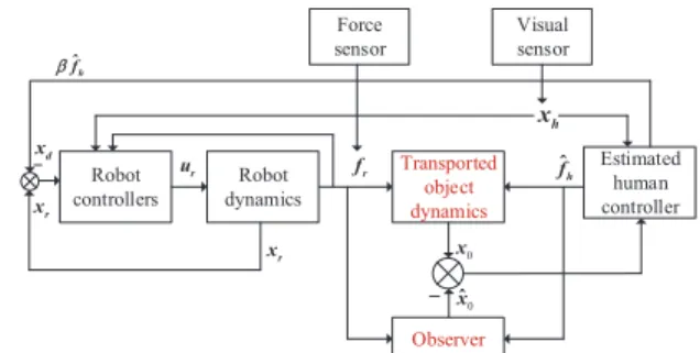
diagram is given in Fig. 2. Although a human-robot co-carrying task is studied as a specific application, the proposed method can be extended to other scenarios of physical human-robot interaction that rely on force and visual sensing, such as human-robot collaborative assembly, tele-operation, sawing, etc. Transported object dynamics Robot controllers Robot dynamics Observer 0 xˆ 0 x r f r x d x Estimated human controller -r x - ur fˆh h x Force sensor Visual sensor h fˆ b
Fig. 2: The proposed control structure.
IV. SIMULATIONS
A. Simulation settings
We consider a scenario where human and robot perform
co-transporting tasks inX−Y plane. The object is chosen as a
0.1m long board which is located parallel to X-axis. In this task, rotation is not considered and only translational motion is involved. A human hand grasps one end of the board, and the other end of the board is held by the robot gripper. The
task objective is to move the object from an initial position to a target position.
We consider the robot as a simple two-link manipulator, where the length and mass of the first link are set as
0.3443m, 4.318kg, and the length and mass of the second
link are set as 0.3443m, 2.152kg. By Lagrange equation,
dynamics parameters Mr(xr),Cr(xr,x˙r) andGr(xr)in (1)
can be calculated based on the robot’s physical parameters for simulating robot’s position and velocity in the task s-pace and the detailed expression can be found in [43]. We
consider the initial position vector of robot gripper xr(0) =
[0.2m,0.25m]T and the initial human hand position vector
xh(0) = [0.1m,0.25m]T. In (3), we consider human motion
intention vector xe = [0.3m,0.35m]T, and human arm
stiff-ness matrix Kh = [0.115N/m,0; 0,0.258N/m]. We consider
that the human arm arrives at xe in 30s, which generates
a prescribed human trajectory xh in Fig. 3(a), and xh(1)
and xh(2) denote uniform linear motions on X-axis and
Y-axis. According to (3), the control input of humanfh can be
simulated whenxh,Khandxeare available as shown in Fig.
3(b), andCo(xo,x˙o) in (19) can be regarded as zero without
rotation. The external forcefrcan be obtained from (19), and
fr(1) andfr(2) denote external forces on X-axis and Y-axis.
We set other crucial parameters as follows: the object mass
in (19) is set as 0.6kg, and β in (27) is set as 0.3. In (6),
RBFNN node number is set as 210, RBFNN centers are set
in the region of [−1,1], and we define the initial value of
the RBFNN weights θi as 0, positive definite gain matrices
Γ1 = Γ2 = 10I210·210, σ1 = 2.2 and σ2 = 0.9. In (8), the
proportional gain matrixKpis defined as[10,0; 0,10], and the
differential gain matrixKdis defined as[5,0; 0,5]. We define
L in (21) as follows: L= 1.51· 0.103,0.1,0.1,0.0 0.19,0.6,0.1,0.2 0.08,0.0,0.2,0.0 0.0,0.2,0.0,0.7 (28) B. Simulation results
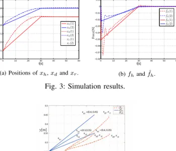
Simulation results about robot’s desired motion xd, gripper
position xr and human motion xh are shown in Fig. 3(a).
It depicts that robot can estimate human motion intention accurately and generates a desired motion to perform the task successfully. We can conclude that the robot gripper position
xr tracks robot’s desired motion xd accurately under our
proposed controller in (8), and tracking errors converge to zero on X-axis and Y-axis. As shown in Fig. 3(a), the motion synchronization of human and robot can be achieved. Indicated
from Fig. 3(b), it is obvious thatfˆhcan estimatefhwell which
illustrates the effectiveness of our proposed observer (21). For evaluating the robustness of our proposed method, we set three different human motion intention vectors as
xe1 = [0.3m,0.35m]T, xe2 = [0.3m,0.35m]T and xe3 =
[0.4m,0.35m]T. Seen from Fig. 4, motion synchronization can
be achieved when human motion intentions are different.
0 10 20 30 40 50 60 0.05 0.1 0.15 0.2 0.25 0.3 0.35 0.4 t[s] Position[m] xh(1) xh(2) xd(1) xd(2) xr(1) xr(2)
(a) Positions ofxh,xdandxr.
0 10 20 30 40 50 60 −0.08 −0.07 −0.06 −0.05 −0.04 −0.03 −0.02 −0.01 0 0.01 t[s] Force[N] ˆ fh(1) ˆ fh(2) fh(1) fh(2) (b)fhandfˆh. Fig. 3: Simulation results.
Fig. 4: Co-transporting considering different human motion intentions.
V. EXPERIMENTS
A. Experiment settings
As shown in Fig. 5(a), the right arm of Baxter robot is employed to cooperate with human to perform co-transporting tasks. Angles, angular velocities and torques can be obtained by sensors in all seven joints. Detailed introduction about Baxter robot can be referred to [44]. Considering both accu-racy and computation efficiency, two computers are utilized in the experiments. One computer is used to calculate the
feedforward inputurf of NN compensation in (4) by Matlab
Simulink, and transfer the compensation values to the other computer by UDP communications. The other computer is used to receive sensory information from Baxter robot, visual
sensor and force sensor, calculate feedback control inputurb
and generate control inputurN N to control the robot by Baxter
Robot Operating System Software Development Kit (RSDK) in Ubuntu 14.04 LTS. Note that Jacobian matrix transpose
JT can be obtained from Python Kinematics and Dynamics
Library (PyKDL), and control torque vector of seven joints is
calculated byJTu
rN N.
Kinect 2 3D depth camera is utilized as a visual sensor for
obtaining human motionxh. Kinect 2 contains a color camera,
a depth sensor and four microphone arrays and provides capabilities in three dimensional (3D) motion capture and voice recognition. It is mounted on the hand of Baxter robot. Quick response detection method is applied in Kinect 2 to obtain the 3D position of the calibration board, which has been fixed on the human side of the board. We can obtain
3D locations of human handxh as the position of calibration
board seen from Fig. 5(b). A calibrated force-torque (F/T) sensor ATI nano17 is used to obtain 6-DOF forces and torques on the robot gripper. Indicated from Fig. 5(b), robot gripper and human hand carry an acrylic board. Coordinate conversion
and filters are utilized in processing collected visual and force sensing information which have been described in Section III.
Then we utilize (15) to transformKx
h toRxh, and utilize
(18) to transform Ff
r to Rfr. Rxh andRfr are utilized for
further controller design in robot reference coordinates.
Windows 7 Unbuntu 14.04 Router Visual sensor Kinect 2 Baxter robot Force sensor ATI Nano 17 Computer 1 Computer 2 Human hand Acrylic board Robot End-effector Calibration board
(a) Experiment platform.
ATI nano17 F/T sensor Baxter robot end-effector Acrylic board Calibration board Human hand
(b) The co-transporting scenario.
Fig. 5: Experiment platform and co-transporting scenario.
B. Experiment results
1) Results with the proposed method: The experiment has
been performed with 4 subjects with ages ranging from 20 to 32. The group is formed of 3 males and 1 female all right-handed, who are from our university, and they have robotic research experiences but are blind to experiment settings. As shown in Fig. 6, human subject B and Baxter robot move the board jointly along the direction indicated by red
arrows, and synchronous motions in up,right,down,leftand
diagonal directions in order in Y-Z plane demonstrate the
effectiveness of our proposed method. Indicated from Fig. 7(a), human subject A/B/C/D and robot co-transport the object in
the diagonal direction from the same initial positions to the
target positions. Due to human motion uncertainties in real
applications, we only ensure similar xhof four subjects. Fig.
7(b) depicts that the task can be accomplished by different human subjects. Sensor noises and rotations around X-axis
result in non-smooth curves ofxhandxr, which may influence
experiment results and cannot be avoided. Fig. 7(b) shows that motion synchronization of robot and Subject B can be achieved
on Y-axis and Z-axis (the board length is deducted fromxron
Y-axis for better comparison in figures). Mean squared error (MSE) is employed to evaluate the robustness of our proposed method, which is defined as follows:
MSE = 1 n n ∑ k=1 [xr,k−xh,k−xb]2 (29)
where xb denotes the vector of the board dimension [l,0]T,
l=0.24m denoting board length on Y-axis. We have added a criterion “Motion Smoothness (MS)” and define it as the distance between the upper and lower envelopes of the robot motion curve. The results of MSE and MS for different subjects are shown in Table I, which illustrates a small tracking error for all subjects and smooth movements. Fig. 8(a) shows that the external forces on robot are smooth and the co-carrying processes are stable. Limited by experimental
equipment,fhcannot be measured directly in our experiment,
so (19) is utilized to approximatively calculate fh on the end
of the board. Table II shows thatfh of four subjects are small
and continuous under our proposed method.
TABLE I: MSE and MS of 4 subjects.
MSE/MS subject A B C D MSEY(cm2) 0.255 0.149 0.124 0.223 MSY(cm) 0.047 0.024 0.016 0.015 MSEZ(cm2) 1.644 1.035 0.529 0.498 MSZ(cm) 0.020 0.018 0.023 0.022
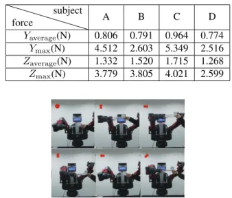
TABLE II: Average and maximal fh of 4 subjects on Y,
Z-axes. force subject A B C D Yaverage(N) 0.806 0.791 0.964 0.774 Ymax(N) 4.512 2.603 5.349 2.516 Zaverage(N) 1.332 1.520 1.715 1.268 Zmax(N) 3.779 3.805 4.021 2.599
Fig. 6: Subject B performs a co-transporting task with Baxter robot along the direction of red arrows.
-0.3 -0.2 -0.1 0 0.1 0.2 0.3 Y[m] 0.15 0.2 0.25 0.3 0.35 0.4 0.45 0.5 0.55 0.6 Z[m] xr, subject A xr, subject B xr, subject C xr, subject D xh, subject A xh, subject B xh, subject C xh, subject D
(a) Co-transporting considering different human subjects.
0 5 10 15 20 25 30 35 40 45 50 t[s] -0.3 -0.2 -0.1 0 0.1 0.2 0.3 0.4 0.5 Position[m] Xh-Y Xr-Y Xh-Z Xr-Z
(b) Motion synchronization of robot and Subject B.
Fig. 7: Human and robot motions.
0 5 10 15 20 25 30 35 40 45 50 t[s] -0.5 0 0.5 1 1.5 2 2.5 3 External force fr[N] fry frz
(a) External forcefrusing the proposed
method. 0 5 10 15 20 25 30 35 40 t[s] -0.5 0 0.5 1 1.5 2 2.5 fr[N] fry frz
(b) External forcefr using PI.
2) Comparisons: We compare our proposed method with VS (Visual Servoing method) and PI (Passive Impedance method) in this section. VS is utilized only with visual sensors to achieve motion tracking, and PI relies on sensory infor-mation from only force/torque senors to achieve compliant interactive behavior.
VS control method is redesigned according to (8) to make
robot track xd towards human motion xh directly rather
than human motion intention xe, and a PD (proportional
differential)-based controller τvision = −KP(xr − xd) −
KD( ˙xr−x˙d) is employed for tracking. The co-transporting
task can not be performed successfully only by VS method, because there exist regid connections between human, board and robot. Therefore, we consider the tracking performance under VS without co-carrying the board for comparison. Figs. 9(a) and 9(b) show motion comparison (after 10s) under different methods (our proposed method, VS and PI), and
the board length is deducted from xr on Y-axis for better
comparison in figures. Seen from Figs. 9(a) and 9(b), there exists a delay in robot motions when VS controller is involved. A traditional PI control method is used for comparison, which is widely used in co-carrying tasks [45]. The desired
impedance model of robot is designed as fr = Ddx˙r +
Kd(xr−xd), whereDd andKd denote damping and stiffness
matrices, and we design Kd as zero for achieving compliant
behaviors in experiments. Seen from Figs. 9(a) and 9(b), the robot motion under PI is less smooth and even includes
oscillations. Indicated from Fig. 8(b), external forcefr is less
smooth than that under our proposed method shown in Fig. 8(a), and human subjects report that they found the interaction
uncomfortable. We conclude from Table III that fh under
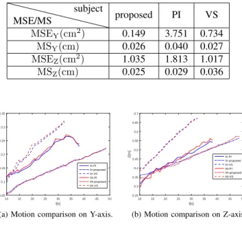
our proposed method is smaller than that under PI, which illustrates that human subjects cost less efforts in the task. From Table IV, we find that our proposed method shows better collaborative performance compared with VS and PI in the task. Notably, Table IV shows better tracking results on Y-axis using VS, but there exists a delay in co-carrying tasks shown in Figs. 9(a) and 9(b), which may lead human to cost more effort for human in co-carrying tasks.
TABLE III: Average and maximalfh on Y, Z-axes.
force method PI proposed Yaverage(N) 1.054 0.791 Ymax(N) 3.177 2.603 Zaverage(N) 1.597 1.520 Zmax(N) 7.542 3.805 VI. CONCLUSIONS
A hybrid framework using visual and force sensing in human-robot co-transporting tasks has been proposed in our paper. Visual sensing has been employed to obtain human motion and force sensing has been used to measure external forces on robots. An observer has been designed for esti-mating control input of human, and robot’s desired motion has been designed based on the observer towards human
TABLE IV: MSE and MS under our proposed method com-pared with PI and VS.
MSE/MS subject proposed PI VS MSEY(cm2) 0.149 3.751 0.734 MSY(cm) 0.026 0.040 0.027 MSEZ(cm2) 1.035 1.813 1.017 MSZ(cm) 0.025 0.029 0.036 10 15 20 25 30 35 40 45 50 t[s] 0.05 0.1 0.15 0.2 0.25 0.3 0.35 Y[m] Xr-PI Xr-proposed Xr-VS Xh-PI Xh-proposed Xh-VS
(a) Motion comparison on Y-axis.
10 15 20 25 30 35 40 45 50 t[s] 0.25 0.3 0.35 0.4 0.45 0.5 0.55 0.6 0.65 0.7 Z[m] Xr-PI Xr-proposed Xr-VS Xh-PI Xh-proposed Xh-VS
(b) Motion comparison on Z-axis.
Fig. 9: Motion comparison.
motion intention. An adaptive controller has been proposed for improving tracking accuracy, and online NNs have been used to compensate for uncertainties in robot’s dynamics. The proposed framework has been validated by comparative simulations and experimental co-carrying tasks.
VII. LIMITATIONS AND FUTURE WORKS
In future works, co-transporting tasks such as human-robot collaborative assembly, tele-operation, sawing, etc will be further designed to evaluate our proposed framework. The calibration board was used for obtaining human motion and it was sometimes not recognized in the experiments. Therefore, more robust machine learning methods [46] [47] [48] will be investigated to localize the human hand by visual sensors without the calibration board. For instance, the Faster-RCNN detection algorithm can be used to localize the human hand position, while SiamRPN tracking algorithm can be utilized to realize real-time tracking. In this work, the interactive experience was described by human subjects verbally and is evaluated by human control efforts. In future works, force sensors will be mounted on the human side of the board for evaluating human interactive experience using objective mea-sures. Human user studies with questionnaires and subjective measures will be also designed.
APPENDIXA
We consider Lyapunov function candidatesV includingVe,
Vk andVx as follows:
Ve= 1 2( ˙e TM r(xr) ˙e+eTKpe) + 1 2 n ∑ i=1 ˜ θi T Γ−i1θ˜i Vk= 1 2( ˙˜x T ox˙˜o+ ˜fhTf˜h+ (vec( ˜Kh)Tvec( ˜Kh)) Vx= 1 2(xh−xe) TK h(xh−xe) (30) Differentiating Veyields: ˙ Ve= ˙eTMr(xr)¨e+ 1 2e˙ TM˙ r(xr) ˙e+ ˙eTKpe+ n ∑ i=1 ˜ θTi Γ−i1θ˙ˆi (31)
where 12(Mr(xr)−2Cr(xr,x˙r))is a skew-symmetric matrix
[43], so we can obtain that 12eT(M
r(xr)−2Cr(xr,x˙r))e= 0.
Substituting (9) and (6), we rewrite (31) according toYoung’s
inequalityas follows: ˙ Ve= ˙eT(Mr(xr)¨e+Cr(xr,x˙r) ˙e+Kpe) + n ∑ i=1 ˜ θTi Γ− 1 i {−Γi[Si(Zi) ˙ei+δiθˆi]} ≤ −e˙TKde˙+ ( ˙xh−x˙d)Tfˆh+ n ∑ i=1 σi 2(||θ ∗ i|| 2− ||θ˜ i||2) (32)
whereKq ≥ ||ε(Z)||, then differentiatingVk yields:
˙ Vk=˜δTδ˙˜+ ˜AThA˙ˆh+ vec( ˜Kh)Tvec(K˙ˆh) =˜δTN1f˜h−δ˜T(L−M1)˜δ−A˜ThN1Tδ˜+ ˜AThβfh−e˙Tf˜h + vec( ˜Kh)Tvec(N1Tδx˜ T h)−vec( ˜Kh)Tvec(βfhxTh) =−δ˜T(L−M1)˜δ+βf˜hTfh−( ˙xh−x˙d)Tf˜h (33) Differentiating Vx yields: ˙ Vx= ˙xThKh(xh−xe) =−x˙Thfh (34) AddingV˙x toV˙ewe obtain: ˙ Ve+ ˙Vx≤ −e˙TKde˙+ ( ˙xh−x˙d)Tfh+ ( ˙xh−x˙d)Tf˜h−x˙Thfh +F ≤ −e˙TKde˙+ ( ˙xTe −x˙ T d)fh+ ˙eTf˜h−x˙Thfh + ( ˙xh−x˙d)Tf˜h+F ≤ −e˙TKde˙−βfhTfh−βf˜hTfh+ ( ˙xh−x˙d)Tf˜h+F (35) whereF = n ∑ i=1 σi 2(||θ∗i||2−||θ˜i||2). So we obtainV˙ as follows: ˙ V = ˙Ve+ ˙Vk+ ˙Vx ≤ −e˙TKde˙−βfhTfh−βf˜hTfh−δ˜T(L−M1)˜δ+βf˜hTfh + n ∑ i=1 σi 2(||θ ∗ i|| 2− ||θ˜ i||2) ≤ −e˙TKde˙−βfhTfh−δ˜T(L−M1)˜δ− n ∑ i=1 σi 2|| ˜ θi||2 + n ∑ i=1 σi 2||θ ∗ i|| 2 (36)
Then we can conclude that variablese,˙ fhandδ˜are bounded
and satisfy a condition as follows λKd||e˙|| 2+β min||fh||2+λL−M1||δ˜|| 2+σi 2||vec(˜θi)|| 2 ≤σi 2||vec(θ ∗ i)|| 2 (37)
where λKd and λL−M1 are the minimal eigenvalues of KD
andKL−M1, respectively,βmin denotes the minimal value of
β, and vec(·) stands for the column vectorization operation.
It follows thate,˙ fh andx˜o can be made arbitrarily small by
choosing sufficiently large λKd, λL and βmin. If θ∗i is zero,
we can conclude thatV˙ = 0 when e˙= 0,fh= 0 and˜δ= 0.
We consider e˙ = 0 in robotic dynamics (9), and obtain that
KPe = 0, so e = 0 and xr = xd. Indicated from fh = 0,
we can obtain xh=xe(Kh̸= 0) or Kh= 0. By considering
˜
δ = 0 in (25) we can obtain that f˜h = 0 which means that
control input of human can be obtained.
The above inequality (37) can be proved by contradiction:
assuming the above inequality is invalid yieldsV <˙ 0and thus
V decreases iteratively. This indicates that||e˙||,||fh||,||˜δ||and
||vec(˜θi)||(and thus the left-hand side of the above inequality)
become even smaller, which contradicts the hypothesis. REFERENCES
[1] B. Siciliano and O. Khatib,Springer handbook of robotics. Springer, 2016.
[2] Z. Li, B. Huang, A. Ajoudani, C. Yang, C.-Y. Su, and A. Bicchi, “Asymmetric bimanual control of dual-arm exoskeletons for human-cooperative manipulations,” IEEE Transactions on Robotics, vol. 34, no. 1, pp. 264–271, 2017.
[3] M. Khoramshahi and A. Billard, “A dynamical system approach to task-adaptation in physical human–robot interaction,”Autonomous Robots, pp. 1–20, 2018.
[4] Y. Li and S. S. Ge, “Human–robot collaboration based on motion in-tention estimation,”IEEE/ASME Transactions on Mechatronics, vol. 19, no. 3, pp. 1007–1014, 2014.
[5] M. S. Erden and T. Tomiyama, “Human-intent detection and physically interactive control of a robot without force sensors,”IEEE Transactions
on Robotics, vol. 26, no. 2, pp. 370–382, 2010.
[6] L. Peternel, N. Tsagarakis, and A. Ajoudani, “Towards multi-modal intention interfaces for human-robot co-manipulation,” in Intelligent Robots and Systems (IROS), 2016 IEEE/RSJ International Conference on, pp. 2663–2669, IEEE, 2016.
[7] T. Lenzi, S. M. M. De Rossi, N. Vitiello, and M. C. Carrozza, “Intention-based emg control for powered exoskeletons,” IEEE Transactions on
Biomedical Engineering, vol. 59, no. 8, pp. 2180–2190, 2012.
[8] D. P. Losey and M. K. OMalley, “Trajectory deformations from physical human–robot interaction,”IEEE Transactions on Robotics, vol. 34, no. 1, pp. 126–138, 2018.
[9] C. Yang, C. Zeng, P. Liang, Z. Li, R. Li, and C.-Y. Su, “Interface design of a physical human-robot interaction system for human impedance adaptive skill transfer,”IEEE Transactions on Automation Science and
Engineering, vol. 15, no. 1, pp. 329–340, 2018.
[10] H. Li, S. Zhao, W. He, and R. Lu, “Adaptive finite-time tracking control of full state constrained nonlinear systems with dead-zone,”Automatica, vol. 100, pp. 99–107, 2019.
[11] W. He, W. Ge, Y. Li, Y.-J. Liu, C. Yang, and C. Sun, “Model identi-fication and control design for a humanoid robot,”IEEE Transactions
on Systems, Man, and Cybernetics: Systems, vol. 47, no. 1, pp. 45–57,
2017.
[12] J. Chen and H. Qiao, “Muscle-synergies-based neuromuscular control for motion learning and generalization of a musculoskeletal system,”
IEEE Transactions on Systems, Man, and Cybernetics: Systems, in press,
DOI: 10.1109/TSMC.2020.2966818, 2020.
[13] H. Qiao, M. Wang, J. Su, S. Jia, and R. Li, “The concept of attractive region in environment and its application in high-precision tasks with low-precision systems,” IEEE/ASME Transactions on Mechatronics, vol. 20, no. 5, pp. 2311–2327, 2014.
[14] G. Xie, A. Shangguan, R. Fei, W. Ji, W. Ma, and X. Hei, “Motion trajectory prediction based on CNN-LSTM sequential model,”SCIENCE CHINA Information Sciences, in press, DOI: 10.1007/s11432-019-2761-y, 2020.
[15] D. Huang, Y. Fu, N. Qin, and S. Gao, “Fault diagnosis of high-speed train bogie based on LSTM neural network,”SCIENCE CHINA
Information Sciences, vol. 64, no. 1, p. 119203, 2020.
[16] M. Bortolini, M. Faccio, F. G. Galizia, M. Gamberi, and F. Pilati, “Design, engineering and testing of an innovative adaptive automation assembly system,”Assembly Automation, vol. 40, no. 3, pp. 531–540, 2020.
[17] G. Wu, J. Sun, and J. Chen, “Optimal linear quadratic regulator of switched systems,”IEEE Transactions on Automatic Control, vol. 64, no. 7, pp. 2898–2904, 2019.
[18] H. Li, Y. Gao, P. Shi, and H.-K. Lam, “Observer-based fault detection for nonlinear systems with sensor fault and limited communication capacity,” IEEE Transactions on Automatic Control, vol. 61, no. 9, pp. 2745–2751, 2016.
[19] B. Gao, X. Li, W. L. Woo, and G. yun Tian, “Physics-based image segmentation using first order statistical properties and genetic algorithm for inductive thermography imaging,” IEEE Transactions on Image
Processing, vol. 27, no. 5, pp. 2160–2175, 2018.
[20] X. Chen, Y. Feng, and C.-Y. Su, “Adaptive control for continuous-time systems with actuator and sensor hysteresis,”Automatica, vol. 64, pp. 196–207, 2016.
[21] X. Chen, C.-Y. Su, Z. Li, and F. Yang, “Design of implementable adap-tive control for micro/nano positioning system driven by piezoelectric actuator,”IEEE Transactions on Industrial Electronics, vol. 63, no. 10, pp. 6471–6481, 2016.
[22] X. Yu, S. Zhang, L. Sun, Y. Wang, C. Xue, and B. Li, “Cooperative control of dual-arm robots in different human-robot collaborative tasks,”
Assembly Automation, vol. 40, no. 1, pp. 95–104, 2019.
[23] C. Yang, G. Ganesh, S. Haddadin, S. Parusel, A. Albu-Schaeffer, and E. Burdet, “Human-like adaptation of force and impedance in stable and unstable interactions,”IEEE Transactions on Robotics, vol. 27, no. 5, pp. 918–930, 2011.
[24] B. Xu, “Composite learning control of flexible-link manipulator using NN and DOB,”IEEE Transactions on Systems, Man, and Cybernetics:
Systems, vol. 48, no. 11, pp. 1979–1985, 2017.
[25] J. Na, Y. Li, Y. Huang, G. Gao, and Q. Chen, “Output feedback control of uncertain hydraulic servo systems,”IEEE Transactions on Industrial
Electronics, vol. 67, no. 1, pp. 490–500, 2019.
[26] K. Zhang and Y. Shi, “Adaptive model predictive control for a class of constrained linear systems with parametric uncertainties,”Automatica, vol. 117, p. 108974, 2020.
[27] J. Na, Y. Huang, X. Wu, G. Gao, G. Herrmann, and J. Z. Jiang, “Active adaptive estimation and control for vehicle suspensions with prescribed performance,”IEEE Transactions on Control Systems
Tech-nology, vol. 26, no. 6, pp. 2063–2077, 2017.
[28] H. Lin, B. Zhao, D. Liu, and C. Alippi, “Data-based fault tolerant control for affine nonlinear systems through particle swarm optimized neural networks,”IEEE/CAA Journal of Automatica Sinica, vol. 7, no. 4, pp. 954–964, 2020.
[29] Y. Ren, M. Chen, and J. Liu, “Bilateral coordinate boundary adaptive control for a helicopter lifting system with backlash-like hysteresis,”
Science China Information Sciences, vol. 63, no. 119203, 2020.
[30] Y. Zhang, J. Sun, H. Liang, and H. Li, “Event-triggered adaptive tracking control for multiagent systems with unknown disturbances,”
IEEE Transactions on Cybernetics, DOI: 10.1109/TCYB.2018.2869084,
2018.
[31] Y. Li, K. P. Tee, R. Yan, W. L. Chan, and Y. Wu, “A framework of human–robot coordination based on game theory and policy iteration,”
IEEE Transactions on Robotics, vol. 32, no. 6, pp. 1408–1418, 2016.
[32] A. Bussy, P. Gergondet, A. Kheddar, F. Keith, and A. Crosnier, “Proac-tive behavior of a humanoid robot in a haptic transportation task with a human partner,” inRO-MAN, 2012 IEEE, pp. 962–967, 2012. [33] L. Rozo, S. Calinon, D. Caldwell, P. Jimenez, and C. Torras,
“Learn-ing collaborative impedance-based robot behaviors,” inTwenty-Seventh
AAAI Conference on Artificial Intelligence, pp. 1422–1428, 2013.
[34] L. Rozo, S. Calinon, D. G. Caldwell, P. Jimenez, and C. Torras, “Learn-ing physical collaborative robot behaviors from human demonstrations,”
IEEE Transactions on Robotics, vol. 32, no. 3, pp. 513–527, 2016.
[35] D. Cehajic, S. Erhart, and S. Hirche, “Grasp pose estimation in human-robot manipulation tasks using wearable motion sensors,” inProceedings of the 2015 IEEE/RSJ International Conference on Intelligent Robots
and Systems (IROS), pp. 1031–1036, 2015.
[36] D. ´Cehaji´c, S. Hirche,et al., “Estimating unknown object dynamics in human-robot manipulation tasks,” inRobotics and Automation (ICRA),
2017 IEEE International Conference on, pp. 1730–1737, IEEE, 2017.
[37] D. J. Agravante, A. Cherubini, A. Bussy, P. Gergondet, and A. Khed-dar, “Collaborative human-humanoid carrying using vision and haptic sensing,” inRobotics and Automation (ICRA), 2014 IEEE International
Conference on, pp. 607–612, IEEE, 2014.
[38] L. Yang, Y. Li, and D. Huang, “Motion synchronization in human-robot co-transport without force sensing,” in2018 37th Chinese Control
Conference (CCC), pp. 5369–5374, IEEE, 2018.
[39] Y. Chen, W. Wang, Z. Abdollahi, Z. Wang, J. Schulte, V. Krovi, and Y. Jia, “A robotic lift assister: a smart companion for heavy payload transport and manipulation in automotive assembly,”IEEE Robotics &
Automation Magazine, vol. 25, no. 2, pp. 107–119, 2018.
[40] W. Wang, R. Li, Y. Chen, Z. M. Diekel, and Y. Jia, “Facilitating human– robot collaborative tasks by teaching-learning-collaboration from human demonstrations,”IEEE Transactions on Automation Science and
Engi-neering, vol. 16, no. 2, pp. 640–653, 2018.
[41] Z. Zhang, W. Wang, Y. Chen, Y. Jia, and G. Peng, “Prediction of human actions in assembly process by a spatial-temporal end-to-end learning model,” tech. rep., SAE Technical Paper, 2019-01-0509, 2019. [42] N. Andreff, R. Horaud, and B. Espiau, “Robot hand-eye calibration using
structure-from-motion,”The International Journal of Robotics Research, vol. 20, no. 3, pp. 228–248, 2001.
[43] W. He, S. S. Ge, Y. Li, E. Chew, and Y. S. Ng, “Neural network control of a rehabilitation robot by state and output feedback,”Journal of Intelligent & Robotic Systems, vol. 80, no. 1, pp. 15–31, 2015. [44] C. Yang, Y. Jiang, Z. Li, W. He, and C.-Y. Su, “Neural control of
bimanual robots with guaranteed global stability and motion precision,”
IEEE Transactions on Industrial Informatics, vol. 13, no. 3, pp. 1162–
1171, 2016.
[45] A. M¨ortl, M. Lawitzky, A. Kucukyilmaz, M. Sezgin, C. Basdogan, and S. Hirche, “The role of roles: Physical cooperation between humans and robots,”The International Journal of Robotics Research, vol. 31, no. 13, pp. 1656–1674, 2012.
[46] Z. Cao, T. Simon, S.-E. Wei, and Y. Sheikh, “Realtime multi-person 2d pose estimation using part affinity fields,” inProceedings of the IEEE
Conference on Computer Vision and Pattern Recognition, pp. 7291–
7299, 2017.
[47] R. Alp G¨uler, N. Neverova, and I. Kokkinos, “Densepose: Dense human pose estimation in the wild,” inProceedings of the IEEE Conference on
Computer Vision and Pattern Recognition, pp. 7297–7306, 2018.
[48] H. Joo, T. Simon, and Y. Sheikh, “Total capture: A 3d deformation model for tracking faces, hands, and bodies,” inProceedings of the IEEE
conference on computer vision and pattern recognition, pp. 8320–8329,
2018.
Xinbo Yu(S’16-M’20) received the B.E. degree in control technology and instrument from the School of Automation and Electrical Engineering, Univer-sity of Science and Technology Beijing, Beijing, China, in 2013 and the Ph.D. degree in control sci-ence and engineering from the School of Automation and Electrical Engineering, University of Science and Technology Beijing, Beijing, China, in 2020. He is currently working as an associate professor in the Institute of Artificial Intelligence, University of Science and Technology Beijing, Beijing, China. His current research interests include adaptive neural networks control, robotics and human-robot interaction.
Wei He (S’09-M’12-SM’16) received his B.Eng. in automation and his M.Eng. degrees in control science and engineering from College of Automation Science and Engineering, South China University of Technology (SCUT), China, in 2006 and 2008, respectively, and his Ph.D. degree in control science and engineering from from Department of Electrical & Computer Engineering, the National University of Singapore (NUS), Singapore, in 2011.
He is currently working as a full professor in School of Automation and Electrical Engineering, University of Science and Technology Beijing, Beijing, China. He has co-authored 2 books published in Springer and published over 100 international journal and conference papers. He was awarded a Newton Advanced Fellow-ship from the Royal Society, UK in 2017. He was a recipient of the IEEE SMC Society Andrew P. Sage Best Transactions Paper Award in 2017. He is serving the Chair of IEEE SMC Society Beijing Capital Region Chapter. He is serving as an Associate Editor of IEEE Transactions on Robotics,IEEE
Transactions on Neural Networks and Learning Systems,IEEE Transactions
on Control Systems Technology,IEEE Transactions on Systems, Man, and
Cybernetics: Systems, SCIENCE CHINA Information Sciences, IEEE/CAA
Journal of Automatica Sinica,Neurocomputingand an Editor ofJournal of
Intelligent & Robotic Systems. His current research interests include robotics, distributed parameter systems and intelligent control systems.
Qing Lireceived his B.S. degree from North China University of Science and Technology, Tangshan, China, in 1993 and the Ph.D degree in control theory and its applications from University of Science and Technology Beijing, Beijing, China, in 2000. He is currently a Professor with the School of Automation and Electrical Engineering, University of Science and Technology Beijing, Beijing, China. He has been a visiting scholar at Ryerson University, Toronto, Canada, from February 2006 to February 2007. His research interests include intelligent control and intelligent optimization.
Yanan Li (S’10-M’14) is a Lecturer in Control Engineering with the Department of Engineering and Design, University of Sussex, UK. He received the B.Eng. and M.Eng. degrees from the Harbin Institute of Technology, China, in 2006 and 2008, respectively, and the PhD degree from the National University of Singapore, in 2013.
From 2015 to 2017, he has been a Research Associate with the Department of Bioengineering, Imperial College London, UK. From 2013 to 2015, he has been a Research Scientist with the Institute for Infocomm Research (I2R), Agency for Science, Technology and Research (A*STAR), Singapore. Dr Li has active research in human-robot interaction and robot control and their applications in semi-autonomous industrial robots, tele-operation robots and rehabilitation robots. He has served as Technical Committee on Bio-mechatronics and Bio-robotics Systems and Technical Committee on Autonomous Bionic Robotic Aircraft, IEEE Systems, Man, and Cybernetics Society, and International Program Committee Member and Session Chair for several conferences in robotics and control. He has led and participated in several research projects funded by Xiamen Municipal Government, EU, Singapore SERC, MDA, etc.
Bin Li received his B.Eng. degree in automation from School of Automation and Electrical Engineer-ing, University of Science and Technology BeijEngineer-ing, Beijing, China, in 2019. He is currently pursuing the M.Eng. degree in control science and engineering from School of Automation and Electrical Engi-neering, University of Science and Technology Bei-jing. His current research interests include intelligent robot control, human-robot collaboration.