A New Approach to Optimize Over Current Relay
Coordination
Ismu Wijayanto1*), Sasongko Pramono Hadi2
1Jurusan Teknik Elektro, Fakultas Teknik, Universitas Gajah Mada, Yogyakarta 2Jurusan Teknik Elektro, Fakultas Teknik, Universitas Gajah Mada, Yogyakarta
email:1[email protected],2[email protected]
Abstract—A power system can not be separated from interference. Interruptions in power system may interfere service continuity and potentially damage equipment due to fault current flow on the line. Therefore, it is needed a protection system that can isolate disturbed area and can avoid equipment damage. Many relays installed in power protection systems, and overcurrent relay is an important protective device and widely installed in the power system. This relay is useful to protect equipment from current spikes during interruption or flashover occurs. An electric power protection system can work optimally if there is coordination of installed overcurrent current relay. This research is expected to be useful for optimizing the overcurrent relay coordination protection.
Keywords—overcurrent relay; protection; coordination I. INTRODUCTION
Anelectric power system composition basically consists of generation, transmission and distribution networks. They are connected to one another to generate, transmit and distribute electric power to used by customer. Electric power systems have benefits and a very vital function in day life activity. Construction and development of the system should be implemented by comprehensive design and considering relevant aspects, so the result system works optimumly, reliably, and economically. Reliability and the ability of an electric power system in servicing customer is highly dependent on the protection system.
Protection system have an important role in detecting any electricity fault and may prevent damage caused electricity fault . A good coordination protection system will isolate disturbance area and prevent blackouts in other areas. This thing will improve the system reliability with maintaining continuity supply to the load. Many relays are installed in electric protection systems and overcurrent relay is important devices and widely installed in the electric protection systems. This relay is useful to protect equipment from surges when fault occurs or flashover occurs.
Overcurrent protection system is better done by coordinating installed overcurrent relays. Coordination of over current relay calculate easily on radial system, but for more complex systems, which consist of many sources and many bus load, it is not easy to carry out the coordination, so
the optimization methods is needed to solve this problem. Over the past two decades, many optimization methods are used to solve the problems of overcurrent relays coordination.
Several methods are conducted to solve the problem of overcurrent relay coordination, they were linear programming, artificial intelegent, genetic algorithm, genetic algorithm, differential evolution, evolutionary algorithm particle swarm optimation ands other methods.
K. K. Li, C. W. So (2000), presents an efficient and reliable evolutionary-based approach to solve the coordination problem of overcurrent relay protection using the evolutionary algorithm (EA) method and tested on an eight-bus system. The results are promising and demonstrate the effectiveness of the proposed approach [1]. K. K. Li, C. W. So (2000), Presented the application of the artificial intelligence (AI) method to obtain a solution of the optimum arrangement for the coordination of overcurrent protection. The proposed approach has been examined and tested on an eight-bus system. The results showed that AI method can optimize relay coordination setting, reducing relay coordination failure, and Improve the reliability of power systems [2]. Timo Keil and Johann Jäger (2008), Presents the pros and cons of the definite time overcurrent standard (DTOC) and inverse definite minimum time (IDMT) relay according to IEC or ANSI[3]. Prashant P. Bedekar, Sudhir R. Bhide, Vijay S. Kale (2009), use linear programming methods to obtain optimum settings in the coordination protection directed over current relay, and simultaneously to avoid the failure of relay operation. The proposed approach is tested on four bus system and the results show that the linear programming method is an efficient tool in solving coordination overcurrent relay problems in the ring distribution system [4]. Prashant P. Bedekar, Sudhir R. Bhide, Vijay S. Kale (2009), confirmed that the genetic algorithm (GA) method can be used to solve the problem of coordinating directed over current relay, At the same time can avoid failure of operation relay. The proposed approach is tested on radial systems and loop distribution systems and provides satisfactory results [5]. Somboonsup Rodporn, Thanatchai Kulworawanichpong, Anant Oonsivilai, Dusit Uthitsunthorn, Ratchadaporn Oonsivilai (2012), presents the use of differential evolution (DE) method to solve problem of optimation coordination overcurrent relay. The results show that the DE method can find the best solution for the problem *) penulis korespondensi
and BFGS [6]. MR Asadi dan SM Kouhsari (2009) Using the particle swarm optimization (PSO) method to obtain a optimum settings solution for coordination overcurrent relay. This study found that the use of PSO method can improve coordination and relay operation time, looking for optimal points in absolute terms and not being trapped in optimal local points [7]. Manohar Sigh, B.K Panigrahi dan Rohan Muherje (2012) Apply Covariance Matrix Adaptation Evolution Strategy (CMA-ES) to solve the problem of overcurrent protection coordination. This method is tested in a loop system and provides optimal coordination results and there is no coordination error between the primary relay and the backup relay [8]. Hebatallah Mohamed Sharaf, Doaa Khalil Ibrahim (2014) adds the current noise direction as a new constraint. The new formula is piloted on IEEE bus 30 system and gives more accurate results of overcurrent relay coordonation setting [9]. M.H. Hussakin, I. Musirin, A.F. Abidin, and S.R.A. Rahim (2013) presented a multi objective approach using the Modified Firefly Algorithm (MFA) method to find overcurrent relay coordination solutions. The simulation results show that the MFA method is able to minimize the relay operation time [10].
One of the new optimization methods based on swarm intelligence is Bat Algorithm (BA).This method is inspired from the behavior of bats in foraging, avoiding obstacles, and looking for nests in the dark [11]. BA method has been tested and shows good performance in solving the problem of engineering optimization. This research proposes BA to solve the problem of protection relay coordination with time minimization as objective function.
II. BASIC THEORY A. Mesh Network System
Mesh system is a system on power electrical that consists of joinery between radial system and loop sistem.This system has several advantages compared with other types of system configuration, which is :
Continuity of electric power supply is maintained to supply the load requirements.
In case of interference on one line, other lines will not disturbed in power distributing.
Mesh network systems have defiency during construction and design. Construction costs incurred for manufacturing mesh systems are still expensive. In terms of design, the degree of difficulty in conducting protection coordination is very high. This difficulty can be seen from equipment connected to each other and the plants connected to each other [17].
Fig. 1 IEEE 30 Buss Mesh Power System B. Interference of Power System
Interfereces that occur in the electric power system, among others, short circuit and overload circuit. Short circuit breakdowns that often occur in electric power systems, they are;
single line to ground fault line to line fault
double line to ground fault
Phase with phase and at the same time from phase to three phase with ground
three phase to ground fault three phase fault
Such interferences cause damage to electrical equipment, reduced system stability, and cessation of electric power distribution continuity[14].
C. Protection in Electric Power Transmission System
Electrical transmission protection system is necessary in order to maintain continuity of electric power distribution to the customer, to improve stability of the electrical power transmission system and protect the electrical equipment that connect to system from damage caused by system interference.
Therefore, protection in electric power transmission system should pay attention to several things as follows:
a) Sensitivity : Sensitivity is the ability of protective relay to react and work responding disturbances occured in system.
b) Selectivity : Selectivity is protection relay’s ability to operate when interference occurs in its protection area or a protection relay can separate the affected part from system.
c) Operating speed : Operating speed is protection relay’s ability tooperate in accordance with the length of time required. The ability of protection system to separate the disturbance as soon as possible from the system so as to reduce the impact caused by the disorder.
d) Reliability : Reliability is the ability of protection relay to always operate properly in various conditions.
e) Economical : In addition to fullfill the requirements of 1 to 4, utilization of protection relay must be adjusted to the lines and secured equipment.
D. Protection Relay
A protection relay is a device arrangement, either electronically or magnetically designed to detect an abnormal state of electrical equipment that may harm the materiel.
If the danger arises, the protection relay will automatically provide a signal or command to open the circuit breaker so that the interrupted part can be separated from the normal system [14]. The protective relay can secure equipment by measuring or comparing its magnitude, such as current, voltage, power, phase angle, frequency, impedance and so on. The device will make an instantaneous decision by slowing down time of opening the breaker or simply marking it without opening breaker.
The function of a protection relay, among others, are: Detect, measure and determine disrupted system parts
and isolate them.
Detect, measure and determine disrupted system parts and isolate them.
Reduces interference effects on undisrupted segment of the system so can operate normally
E. Over current Relay
Overcurrent relay is a relay that operates when the current flowing in a power system line exceeds the specified current value constraint. Relay will work when If > Ip and relay won’t work when If <Ip. Ip represents the value of current expressed to the secondary winding CT (Current Transformer) and If represents the rated noise current expressed to the secondary winding CT (Current Transformer).This over current relay can be inverse time overcurrent relay, definite time overcurrent relay, instantaneous overcurrent relay [9].
1) Definite Time Over Current Relay: Definite time over current relays is relay that can be adjusted operating time based on different current levels.
Fig 2. Characteristics Definite Time Over Current Relay This type of rele is often used to cut off power flow at the closest interference quickly according to time delay that has been set. This relay works when the current detected by relay exceeds its setpoint pickup so that all current levels passing through the setpoint pickup limit will be disconnected at the same time [17]. Figure 2 shows the characteristics of the
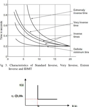
2) Inverse Time Overcurrent Relay : Inverse Time Overcurrent Relay has a reversed action between the time of the release operation and the fault current. This is shown when there is a very large current fault then the operating time of the relay is fast or small and vice versa. The relationship of these two parameters is represented by a TCC curve (Time Current Curve). This curve is equipped by time dial scale, which is longer time dial, then longer relay operation time and vice versa. Characteristic invers time over current relay explained on IEC 60255-3 and BS 142 standard. Invers time protection is distinguished by its curvature gradient, ie inverse, very inverse, and extremely inverse. Their characteristic shown at figure 3. In addition, this inverse curve is often obtained with the minimum inverse definite minimum time (IDMT) where as the current increases, the operating time decreases faster as it approaches its minimum definite time [17]. Characteristics of inverse time over current relay can be seen in Figure 3.
3) Instantaneous Over Current Relay : Instantaneous overcurrent relay works with no time delay operation of the relay. Generally these relays work in less than 0.08 seconds, but these relays can still work at 0.1 seconds. . Characteristics of instantaneous over current relay can be seen in Figure 4. F. Setting of Over Current Relay
There is a maximum and minimum limit current setting for the overcurrent relay, calculated from the amount of current flowing in line. The maximum and minimum limits are formulated as follows,
Fig 3. Characteristics of Standard Inverse, Very Inverse, Extremely Inverse and IDMT
Maximum limit - maximum current setting on overcurrent relay need to calculate the short circuit current passing through relay. A three phase short circuit in the maximum generation will cause the flow of maximum fault current and short circuit interfaces will cause the flow of minimum fault current. Relay must be able to respond two condition that is maximum condition and minimum condition. Minimum Limit - Basically the minimum limit of
overcurrent relay is relay should not operate when full load current flows.
In relay settings, to set the amount of pickup current determined by tap selection.: Selection of tap level can be obtained with the following formula:
= (1)
Iset is a pickup current in amperes with 1.05In <Iset <1.4In restrictions . The limit is taken from the British standard BS142[17]. The CT ratio is the value of current passing through relay on primary CT rather than secondary winding CT. The time dial setting (TDS) - also called time multiplier setting (TMS) - is a setting to determine relay operating time. Based on IEC 60255 time dial determination of each inverse characteristic curve is defined in Table 1 [18].
TABELI.
INVERSE CHARACTERISTIC CURVE Relay Characteristic Standar IEC 60255
Standard Inverse = 0.14 ( ). ∙ Very Inverse = 13.5 ( ) − 1∙ Extreemly Inverse = 80 ( ) − 1∙
Long time Standard Earth
fault = 120
( ) − 1∙
III. BATALGORTIHM
Bat algorithm (BA) is a new type of metaheuristic algorithm introduced by Xin She Yang in 2010 [11]. This algorithm is inspired by the behavior of bats. Bats are amazing animals because they are the only mammal that has wings to fly and have sophisticated capabilities in echolocation. Bats use a type of sonar called an ecolocation to detect food, avoid obstacles and search for nests in the dark. Bats emit high-frequency sound pulses and listen to echoes that bounce back from nearby objects.
The pulses emitted vary and can be linked to hunting strategies, depending on the species. Most bats use a modulated signal frequency that is about 1 octave long, while others often use constant frequency signals for ecolocation. With the ability to ecolocation, bats can fly in the dark to find food without bumping into anything.
The development of an algorithm that is inspired by the behavior of this bat ideal based on three rules as follows:
a. Bats use echolocation for sensing distance and distinguish between food and hurdles even in the dark. b. Bats fly at random in search of food with the speed v at
position x with a fixed frequency f, wavelength λ and the variation of the noise level (A) in search of food.
c. The noise level can be varied in many ways, it can be assumed the noise level varies from a maximum (positive) constant value A0 to minimum (Amin). The main steps of the BA is starting from the initial set of bat populations, each of which is determined by the initial position (initial solution), generating pulses and random noise, and how often. During the iterative process / loop, all the bats will move from the initial solution to the global best solution (s). after moving, if there are bats find a better solution, then the bat will update the pulse emission and noise levels. During the iteration, the best solution is always updated. Finally, the best solution is the solution to the problems solved by this algorithm.
Based on Figure 5 it can be seen that the BA method has some similarities with PSO procedures such as a control variable to adjust the search area of each particle with Pbest the best position of every particle, Gbest the global best position. Simply put, the method can be considered as BA balanced combination of PSO with a local search method intensively controlled with the noise level (A) and pulse rate (r). A0 the initial value can be set in the range [1,2] and the initial value r0 in the range [0,1]. During the iteration process the value of A will be close to 0 and the value of r close to r0. This shows bats have found pace or found a new global solution. A and R values will be updated if it has been found that the new fitness (fnew) for each particle. Update the value of A and r involve constants α and γ.
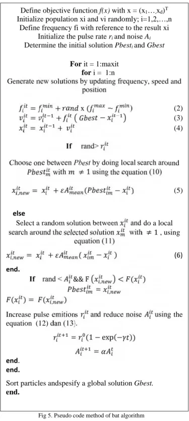
Pseudo code method of bat algorithm is described in figure 5 [12].
Fig 5. Pseudo code method of bat algorithm IV. RESEARCH MODELING
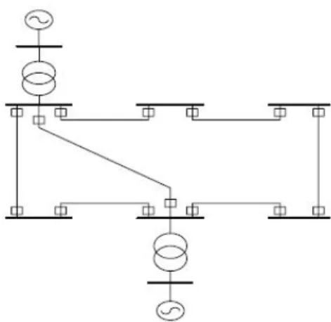
Electrical system used is the transmission system 150 kV IEEE 8 bus, consisting of two generator units, two transformer units, eight buses and fourteen over current directional relay. The system used can be seen in Fig 6.
The relays used in this research are over current relay type Standard Inverse. The tap current setting value used in this study can be seen in table II [19].
The problem of over current relay coordination in the system can be expressed as optimization problem, with the sum of relays operating time in the system, from the closest to disturbance, should be minimized.
min = , (7)
with ti,i is main relay operation time, that closest to the interference. While the coordination requirements are expressed in the following equation :
, − , ≥ (8)
with tbi,i is operating time of the backup relay, that closest to
the interference and CTI (Coordination Time Interval) Is time of coordination interval. In this study CTI used for 0.3 seconds[19].
Meanwhile the constraint specified is as follows:
, ≤ , ≤ , (9)
with t i,min is minimum operation time and t i,max is maximum operation time. Relay timing is calculated using standard inverse curve characteristics, Then the general form becomes
=
( ( ) ) (10)TMS : Time Multiplier Setting PSM : Plug Setting Multiplier λ : 0.14
γ : 0.02 with PSM =
Fig 6. Single Line Transmission System 150 kV IEEE 8 bus Define objective function f(x) with x = (x1…,xd)T
Initialize population xi and vi randomly; i=1,2,…,n Define frequency fi with reference to the result xi
Initialize the pulse rate riand noise Ai
Determine the initial solution Pbestiand Gbest
For it = 1:maxit for i = 1:n
Generate new solutions by updating frequency, speed and position
= + x( − ) (2)
= + − (3)
= + (4)
If rand>
Choose one between Pbest by doing local search around with ≠ 1using the equation (10)
, = + ( − ) (5)
else
Select a random solution between and do a local search around the selected solution with ≠ 1, using
equation (11) , = + ( − ) (6) end. If rand < && F , < ( ) = , ( ) = ( , )
Increase pulse emitions and reduce noise using the equation (12) dan (13).
= (1 − exp(− )) =
end.
end.
Sort particles andspesify a global solution Gbest. end.
TABELII.
CTRATIODATAONEACHRELAY Rasio Current Transformer
Rele no CT Ratio Rele no CT Ratio
1 240 8 240 2 240 9 160 3 160 10 240 4 240 11 240 5 240 12 240 6 240 13 240 7 160 14 160
Equation (10) can be simplified to be:
=( ) (11)
Equation (5) substituted on (1), obtain an objective function that will minimize, ie:
min = ( ) (12)
The TMS value is determined by the optimization method, which in this case using Bat Algorithm method.
V. RESEARCH METHODS
Coordination of overcurrent relay protection system on the transmission system 8 bus 150kV IEEE is a system that will be tested using the BA method. Modeling of transmission network system based on data in previous research. A short circuit current calculation is used to find the current flowing in each relay when a fault occurs. Short circuited currents flowing in each relay used to find out the characteristic parameters of relay operation time when interference occurs and is used to determine relay parameters to obtain optimal coordination [18].
Tests aimed to find minimum TMS using Bat Algorithm method, in this case the author will use Matlab R2012b software. The planned stages are as follows. The first step is initialize parameters in BA method by determining value of the constants. Furthermore initialize current setting main relay and backup relay.. Next simulate the data according to BA procedure until maximum iteration and he result is TMS of all relay. The fourth step is to analyze each data to find out the optimal experiment. The final stage of this research is making reports. Figure 7 described the flow diagram of this research.
VI. CONCLUSION
This paper is a preliminary explanation of research about optimization coordination directed over current relay by using Bat Algorithm method. The method is used to determine the
minimum TMS value, So it is expected to obtain better coordination results from previous research.
Fig 7. Diagram flow of research
Single line diagram
Calculate short circuit current at all bus
short circuit data
Inisialisation :
a. Population (n)
b. Maximum Iterasi (maxit)
c. Frequency (fr) d. Velocity (v) e. Position (x) f. Loudness (A) g. Pulse rate (r) start
1. Calculate Initial Fitness 2. Define Initial Pbest dan Gbest
Iter = 1 : maxit 1. Update frequency (fr) 2. Update velocity (v) if rand(0.1)>1 Update fitness (fn) If rand(0.1)<A&fn<1 1. Update f = fn
2.update pulse rate (r) dan loudness level (A)
Update Pbest dan Gbest
Iter = maxit end 1. 1. Choose a solution among the population (x) 2. 2. Do a local search around the selected x
REFERENCES
[1] K. K. Li, C. W. So. “Evolutionaryalgorithm (EA)for protection relay setting coordination” IEEE 2000
[2] K. K. Li, C. W. So. “Intlelligent method for protection coordination” IEEE 2000
[3] Timo Keil and Johann Jäger. “ Advanced coordination method for overcurrent protection relays using nonstandard tripping characteristic “ IEEE 2008
[4] Prashant P. Bedekar, Sudhir R. Bhide, Vijay S. Kale. “coordination of overcurrent relays in distribution system using linear programming technique” IEEE 2009
[5] Prashant P. Bedekar, Sudhir R. Bhide, Vijay S. Kale. “coordination of overcurrent relays in distribution system using genetic algorithm” IEEE 2009
[6] Somboonsup Rodporn, Thanatchai Kulworawanichpong, Anant Oonsivilai, Dusit Uthitsunthorn, Ratchadaporn Oonsivilai. “optimal coordination of over-current relays using differential evolution (DE)” IEEE 2012
[7] M. R. Asadi, S. M. Kouhsari. “Optimal Overcurrent Relays Coordination using Particle-Swarm-Optimization Algorithm” IEEE 2012
[8] Manohar Singh, B.K. panigrahi, Rohan Mukherjee. “Optimum Coordination of Overcurrent Relays Using CMA-ES Algorithm” IEEE 2012
[9] Hebatallah Mohamed Sharaf, Doaa Khalil Ibrahim. “Protection Coordination of Directional Overcurrent Relays Considering Fault Current Direction” IEEE 2014
[10] M.H. Hussain, I. Musirin, A.F. Abidin, and S.R.A. Rahim. “Multi -Objective Approach for Solving Directional Overcurrent Relay Problem Using Modified Firefly Algorithm” IEEE 2013
[11] X.S. Yang. “ A New Metaheuristic Bat- Inspired Algorithm” Nat.Inspired.Coop. Strateg. Optim.(NISCO 2010), pp. 65-74, 2010 [12] Zaenal Abidin. “ Studi OPF menggunakan Metode Bat Algorithm”
UGM Paper 2014
[13] X.S. Yang and A.H Gandomi, “Bat Algorithm : a novel approach for global eenginering optimation,” Eng. Comput., vol29, no 55, pp 464 -483, 2012
[14] Bonar Pandjaitan.“Praktik-praktik Proteksi Sistem Tenaga Listrik”CV Andi Offset Yogyakarta 2012
[15] Mochamad Anggi Firmansyah, Margo Pujiantara dan Heri Sur yoatmojo. “Studi Kasus Skema Proteksi Adaptive Overcurrent Pada Beban Auxiliary PLTU Perak Memperhatikan Units Cogeneration” ITS Paper 2012
[16] Dani Brami Purwosetyo, Margo Pujiantara, Heri Suryoatmojo. “koordinasi proteksi relay arus lebih dengan metode fuzzy logic plant pt.KPI” ITS Paper 2011
[17] Aditya Descara Putra, “Optimisasi Koordinasi Directional Over Current Relay (DOCR) pada Sistem Distribusi Mesh Menggunakan Modified Adaptive Particle Swarm Optimization (MAPSO) dengan Pembangkit Tersebar” ITS Proceeding 2016
[18] Beni A.R, “Optimalisasi Koordinasi DOCR pada Jaringan Transmisi 150KV Menggunakan SV-MPSO”, Scribd 2010
[19] Septian D, “ Koordinasi Optimal Rele Directional Overcurrent Relay Pada Sistem Transmisi 150 Kv Menggunakan Hybrid Particle Swarm Optimization Time Varying Acceleration Coefficient (PSO-TVAC), ITS Paper 2010