Masters Theses Student Theses and Dissertations
Fall 2007
Current measurement in power electronic and motor drive
Current measurement in power electronic and motor drive
applications - a comprehensive study
applications - a comprehensive study
Asha PatelFollow this and additional works at: https://scholarsmine.mst.edu/masters_theses Part of the Electrical and Computer Engineering Commons
Department: Department:
Recommended Citation Recommended Citation
Patel, Asha, "Current measurement in power electronic and motor drive applications - a comprehensive study" (2007). Masters Theses. 4581.
https://scholarsmine.mst.edu/masters_theses/4581
This thesis is brought to you by Scholars' Mine, a service of the Missouri S&T Library and Learning Resources. This work is protected by U. S. Copyright Law. Unauthorized use including reproduction for redistribution requires the permission of the copyright holder. For more information, please contact [email protected].
CURRENT MEASUREMENT IN POWER ELECTRONIC AND MOTOR DRIVE APPLICATIONS – A COMPREHENSIVE STUDY
by
ASHABEN MEHUL PATEL
A THESIS
Presented to the Faculty of the Graduate School of the UNIVERSITY OF MISSOURI-ROLLA
In Partial Fulfillment of the Requirements for the Degree
MASTER OF SCIENCE IN ELECTRICAL ENGINEERING 2007
Approved by
_______________________________ _______________________________ Dr. Mehdi Ferdowsi, Advisor Dr. Keith Corzine
____________________________ Dr. Badrul Chowdhury
© 2007
ASHABEN MEHUL PATEL All Rights Reserved
ABSTRACT
Current measurement has many applications in power electronics and motor drives. Current measurement is used for control, protection, monitoring, and power management purposes. Parameters such as low cost, accuracy, high current measurement, isolation needs, broad frequency bandwidth, linearity and stability with temperature variations, high immunity to dv/dt, low realization effort, fast response time, and compatibility with integration process are required to ensure high performance of current sensors. Various current sensing techniques based on different physical effects such as Faraday’s induction law, Ohm’s law, Lorentz force law, magneto-resistance effect, and magnetic saturation are studied in this thesis. Review and examination of these current measurement methods are presented.
The most common current sensing method is to insert a sensing resistor in the path of an unknown current. This method incurs significant power loss in a sense resistor at high output currents. Alternatives for accurate and lossless current measurement are presented in this thesis. Various current sensing techniques with tuning and self-calibration for accurate and continuous current measurement are also discussed. Isolation and large bandwidth from dc to several kilo-hertz or mega-hertz are the most difficult, but also most crucial characteristics of current measurement. Electromagnetic-based current sensing techniques, which are used to achieve these characteristics, are analyzed. Many applications require average current information for control purposes. Different average current sensing methods of measuring average current are also reviewed.
ACKNOWLEDGEMENT
I owed thanks to many people who helped me through the Master’s program at the University of Missouri-Rolla. My parent-in-laws deserve thanks for being so loving, supportive, and patient during all my years in graduate school. I am deeply indebted to my advisor, Dr. Mehdi Ferdowsi, whose stimulating suggestions and encouragement helped me throughout this research and the writing of this thesis. He provided expertise, inspiration, and invaluable support for this research, without which my studies could not have completed.
I would like to extend my sincere appreciation to Dr. Keith Corzine and Dr. Badrul Chowdhury for serving as my committee members and examining this thesis. The financial assistance provided to me in the form of a Graduate Research Assistantship through the Department of Electrical Engineering at the University of Missouri-Rolla is gratefully acknowledged.
Finally, I wish to thank my husband Mehul, who tricked me into the Master’s program in the first place and without whom I could have never finished.
TABLE OF CONTENTS
Page
ABSTRACT ... iii
ACKNOWLEDGEMENT ... iv
LIST OF ILLUSTRATIONS ... viii
LIST OF TABLES ... xi
SECTION 1. INTRODUCTION ... 1
1.1. MOTOR DRIVES ... 1
1.2. POWER ELECTRONIC CONVERTERS ... 3
1.3. PROTECTION AND MONITORING ... 4
1.4. BATTERY APPLICATIONS ... 5
1.5. SELECTION CRITERIA ... 5
1.6. LOCATIONS FOR SENSING CURRENT ... 6
1.7. THESIS ORGANIZATION ... 8
2. RESISTIVE-BASED CURRENT SENSING TECHNIQUES ... 9
2.1. RESISTIVE-BASED CURRENT SENSING TECHNIQUE USING AN EXTERNALLY ADDED SENSE RESISTOR ... 9
2.2. RESISTIVE-BASED CURRENT SENSING TECHNIQUE USING THE INTERNAL RESISTANCE OF AN INDUCTOR ... 11
2.3. MOSFET RDS-BASED CURRENT SENSING TECHNIQUE ... 12
2.4. CURRENT-SENSING POWER MOSFET-BASED CURRENT SENSING TECHNIQUE ... 13
2.5. PWM-VSI SWITCHING STRATEGIES ... 16
2.6. CURRENT SENSING TECHNIQUES FOR PWM-VSI DRIVEN AC MOTOR USING EXTERNALLY ADDED SENSE RESISTORS ... 19
2.6.1. An Externally Added Sense Resistor in Each Leg of the Inverter. ... 19
2.6.2. Externally Added Sense Resistors in Series with Motor Phases. ... 21
2.6.3. An Externally Added Sense Resistor with DC Link. ... 22
2.7. MOSFET RDS-BASED CURRENT SENSING FOR PWM-VSI DRIVEN AC MOTOR ... 24
2.8. CURRENT-SENSING POWER MOSFET-BASED CURRENT SENSING TECHNIQUE FOR PWM-VSI DRIVEN AC MOTOR ... 25
2.9. COMPARISION BETWEEN RESISTIVE-BASED CURRENT SENSING TECHNIQUES ... 26
3. ELECTROMAGNETIC-BASED CURRENT SENSING TECHNIQUES ... 28
3.1. CURRENT MEASUREMENT TECHNIQUES USING CURRENT TRANSFORMERS ... 28
3.1.1. Using the Existing Inductor as the Primary of a Transformer. ... 32
3.1.2. AC Current Transformer with Sample-and-Hold Circuit. ... 33
3.1.3. Current Measurement using AC and Unidirectional Current Transformers. ... 36
3.1.4. DC Current Transformer. ... 40
3.2. CURRENT MEASUREMENT TECHNIQUES USING AIR CORE ... 40
3.2.1. Rogowski Coil Current Sensor. ... 41
3.2.2. Planar Rogowski Coil Current Sensor. ... 43
3.3. CURRENT MEASUREMENT TECHNIQUES USING HALL-EFFECT .. 46
3.3.1. Open-loop Hall-Effect Current Sensor. ... 48
3.3.2. Closed-loop Hall-Effect Current Sensor. ... 50
3.3.3. Combination of an Open-loop Hall-Effect Current Sensor with a Current Transformer. ... 52
3.4. SATURABLE INDUCTOR CURRENT SENSORS ... 54
3.5. MAGNETO-RESISTIVE CURRENT SENSOR... 58
3.7. COMPARISION BETWEEN ELECTROMAGNETIC-BASED
CURRENT SENSING TECHNIQUES ... 65
4. CURRENT SENISNG TECHNIQUES WITH SELF-TUNING AND/OR AUTO-CALIBRATION ... 68
4.1. MOSFET RDS-BASED CURRENT SENSING TECHNIQUE WITH REAL-TIME SELF CALIBRATION ... 68
4.2. CURRENT SENSING TECHNIQUE USING THE INTERNAL RESISTANCE OF AN INDUCTOR AND THE FILTER ... 72
4.2.1. Filter-based Current Sensing with Temperature Compensation. ... 76
4.2.2. Filter-based Current Sensing with Accurate RL. ... 77
4.2.3. Filter-based Current Sensing with Self-tuning. ... 79
4.2.4. Combined-Sense Technique. ... 80
4.2.5. Filter-based Current Sensing with Self-tuning and Self-calibration . 82 4.3. COMPARISON BETWEEN CURRENT SENSING TECHNIQUES WITH SELF-TUNING AND/OR AUTO-CALIBRATION... 86
5. AVERAGE CURRENT SENSING TECHNIQUES ... 87
5.1. FILTER-BASED AVERAGE CURRENT SENSING ... 87
5.2. CURRENT TRANSFORMER-BASED AVERAGE CURRENT SENSING ... 89
5.2.1. Average Current Measurement using Two Current Transformers.... 89
5.2.2. Average Current Measurement using One Current Transformer. ... 90
5.2.3. Average Current Sensing by Adding the Second Winding on the Existing Inductor. ... 91
5.3. COMPARISION BETWEEN AVERAGE CURRENT SENSING TECHNIQUES ... 92
6. SUMMARY ... 93
BIBLIOGRAPHY ... 96
LIST OF ILLUSTRATIONS
Figure Page
1.1. Possible current sensing locations in typical power switching stage ... 7
1.2. Possible current sensing locations in motor drives ... 8
2.1. Current sensing using an externally added sense resistor ... 9
2.2. Current sensing using the internal resistance of an inductor ... 11
2.3. MOSFET RDS-based current sensing ... 12
2.4. Current-sensing power MOSFET ... 14
2.5. Current-sensing power MOSFET-based current sensing ... 15
2.6. PWM-VSI driven ac motor ... 17
2.7. Switching sequence of a 180° VSI conduction ... 17
2.8. Switching sequence of a 120° VSI conduction ... 19
2.9. Motor current measurement using an externally added sense resistor in each leg of VSI ... 20
2.10. Motor current sensing using externally added line sense resistors ... 21
2.11. DC link current sensing using an externally added sense resistor ... 22
2.12. MOSFET RDS-based current sensing technique for motor current detection ... 24
2.13. Current-sensing power MOSFET-based current sensing technique for motor current detection ... 25
3.1. Current transformer ... 29
3.2. Basic circuit of single turn primary current transformer ... 30
3.3. Current measurement using the existing inductor as the primary of a transformer 32 3.4. Inductor current estimation using two ac current transformers... 33
3.5. Current, voltage, and sample-and-hold circuit waveforms for CT1 ... 34
3.7. Unidirectional current transformer waveforms ... 38
3.8. Current sensing using unidirectional and ac current transformers ... 39
3.9. Current measurement using dc current transformer ... 40
3.10. Rogowski Coil current sensor ... 41
3.11. Planar Rogowski Coil current sensor ... 44
3.12. Planar Rogowski Coil current sensor with two concentric loops ... 45
3.13. Hall-effect principle ... 46
3.14. Open-loop Hall-effect current sensor with single turn primary ... 48
3.15. B-H loop for open-loop Hall-effect current sensor ... 49
3.16. Open-loop Hall-effect current sensor with a multi-turn primary ... 50
3.17. Closed-loop Hall-effect current sensor ... 51
3.18. Combination of an open-loop Hall-effect current sensor and a current transformer ... 52
3.19. Broad bandwidth provided by combination of an open-loop Hall-effect current sensor and a current transformer ... 53
3.20. Saturable inductor current sensor ... 55
3.21. Saturable inductor and its equivalent circuit ... 55
3.22. Current response of a saturable inductor to a voltage step ... 56
3.23. Voltage steps and current response of a saturable inductor ... 57
3.24. MR strip and resistance verses magnetic field for MR device ... 59
3.25. Barberpole MR device and resistance verses magnetic field for barberpole MR device ... 60
3.26. Four barberpole MR devices in a Wheatstone bridge configuration ... 61
3.27. Barberpole MR sensors with compensation circuit... 62
3.28. Polarimetric fiber optic current sensor ... 64
4.2. Error in the inductor current ... 70
4.3. Duty cycle adjustment ... 72
4.4. Equivalent circuit of Rsense ... 72
4.5. Filter-based current sensing technique ... 73
4.6. Voltage VCf and VRL, when
τ
C=
τ
L ... 754.7. Voltage VCf in steady state ... 75
4.8. Filter-based current sensing with temperature compensated network ... 76
4.9. Voltage VCf and VRL, when
τ
C=
τ
L, and resistor RCf is added into the circuit ... 774.10. Filter-based current sensing with accurate RL ... 78
4.11. Digital auto-tuning circuit ... 80
4.12. Combined-sense technique ... 80
4.13. Voltages Va and Vb in combined-sense technique ... 81
4.14. Filter-based technique with self-tuning and self-calibration ... 82
4.15. Tuning, calibration, and normal operation for filter-based current sensing technique ... 83
4.16. Tuning operation for filter-based current sensing technique ... 84
4.17. Calibration operation for filter-based current sensing technique ... 85
5.1. Filter-based average current sensing ... 87
5.2. Average inductor current sensing using two current transformers ... 89
5.3. Average inductor current sensing using one current transformer ... 90
5.4. Voltage VR1 and VC2 for average current measurement ... 91
5.5. Average inductor current sensing by adding second winding on the existing inductor... 91
LIST OF TABLES
Table Page
1.1. Selection criteria for a current sensor ... 6 2.1. Different states of a 180° VSI conduction ... 18 2.2. Different states of a 120° VSI conduction ... 19 2.3. DC link current for a PWM-VSI driven motor with 180° and 120° conduction .... 23 2.4. Comparative overview of resistive-based current sensing techniques ... 27 3.1. Comparative overview of electromagnetic-based current sensing techniques ... 65 4.1. Comparative overview of current sensing techniques with self-tuning and/or
auto-calibration... 86 5.1. Comparative overview of average current sensing techniques ... 92 6.1. Applications of resistive-based and electromagnetic-based current sensing
1. INTRODUCTION
To be able to control, protect, or monitor a system, certain information about the system is required. In electrical systems this information mainly consists of instantaneous, peak, or average values of the voltage and current signals. Hence, accuracy of current measurement plays an important role in the dynamic performance, efficiency, and safety of an electrical system. Knowing the current information about a system is also important for power management purposes. Applications of current sensing in motor control and power conversion are the main focal points of this thesis. Several detailed descriptions of such systems are provided in the following sub-sections.
1.1. MOTOR DRIVES
Motor current is used as a control variable in motor drives. Vector control and direct torque control require current sensing for control purposes [1-8]. Speed sensorless and voltage sensorless control approaches require motor current measurement to provide accurate control with lower cost, noise, and complexity. Motor current measurement is also required to remove torque ripple in order to provide smooth torque [9, 10]. Modern motor drives are beginning to be digitally controlled and the control elements of such drives require accurate motor current feedback. Therefore, current sensing is of great importance to digitally controlled ac motor drives [11]. Current controlled pulse width modulation (PWM) inverters are used to serve as ac drives. These controllers are classified as hysteresis, ramp comparison, and predictive controllers, all of which require motor current information to determine inverter switching states [12]. Furthermore, information of stator parameters is important for several control schemes. Stator current
measurement is used for the estimation of these parameters [13]. Stator current information is also used for rotor velocity tracking control instead of measuring both rotor flux and velocity [14].
Motor current information is also required to detect rotor position and to check the motor’s insulation condition in several applications. Starting from an unknown rotor position may create temporary reverse rotation or starting failure in permanent magnet motors, which is not acceptable in many applications. Rotor position can be detected by using phase current information [15]. Electrical insulation is the most critical component for operation of electrical motors. Stator insulation failure during motor operation can lead to motor failure, resulting in a costly outage. Insulation condition indicators such as capacitance and dissipation factor are calculated based on the measurement of the differential leakage currents of each phase winding [16].
Current sensing is also important for safety and efficient regulation of all the equipment using industrial motor drives, for example, a motor which is used to open and close elevator doors. An elevator door must react to an object or a person hindering closure. The obstacle detection in the elevator is performed by sensing motor currents. The obstacle creates higher torque, which causes higher currents in the motor. This current information is used to trigger the signal to open the door. Motor current measurement is also important for the elevator’s smooth acceleration and stopping and for placing the cabin exactly level to its destination [17]. Another example is speed control in a forklift. The motor in the forklift is required to adjust the speed and the ascending and descending of the fork. For smooth and steady forklift operation, motor current information in the forklift is required to lift the fork with the same precision and
speed regardless of the amount of load it needs to transport. By measuring the motor current, the forklift adjusts the power required to perform the task.
1.2. POWER ELECTRONIC CONVERTERS
A current sensor in a power electronic converter is used to measure the constantly varying current in order to provide feedback for control purposes. This leads to the accurate and smooth adjustment of converter operation. Current-mode control is implemented in converters to regulate the output voltage. Current-mode control approaches for converters are classified as peak, average, valley, hysteretic, PWM conductance, and output current feed-forward control. All current-mode control types require inductor waveform information to provide appropriate transient response [18-23].
Current sensing in converters is also required for mode hoping, current sharing, ripple cancellation, and integrated power electronic modules (IPEMs). In mode hoping, the sensed converter current is used to determine when to switch between continuous conduction mode and discontinuous conduction mode [24]. Current information is required for current sharing in parallel or multi-phase converters so that the stress among the paralleled dc–dc converters is balanced [25]. In some applications, an active ripple filter is required in power electronic converters to cancel the current ripple [26]. This active ripple filter requires information about converter current. IPEMs are used in vehicles to reduce cost, package size, and interconnect. Current sensing is the most important requirement for an IPEM [27, 28].
Converter current information is also important for power generation applications, for example, inverters used in gas co-generators. In gas co-generators, gas is used to produce steam to drive the turbine to produce electricity through an inverter. This inverter
is directly connected to the household electrical network. To ensure that the output of the inverter is perfectly matched with the electrical network, the output current of the inverter must be known. The grid needs to be supplied with continuous power at a controlled frequency and voltage [29]. Another example is wind generation. The electricity produced by on-shore or off-shore wind turbine generators needs to be safely fed into the grid. To do so, it is required to transform and optimize the generation of electricity from the wind turbine. Current measurement is required for every converter in wind energy turbines to enable optimal control and protection. Current sensors also continuously measure the current in the converters to position the turbine in relation to the wind [30].
1.3. PROTECTION AND MONITORING
Protecting supply circuits against overloading conditions requires the system to sense its current delivery. The over current is a severe fault situation that can result in the failure of the device if appropriate action is not taken in time. The over current is caused by a short circuit, malfunction, or component failure. Current sensing is required for fault detection and its minimization [31, 32]. It enables emerging state-of-art switching supplies to improve transient response, efficiency, and compensation performance [33]. Current measurement is also required for ground fault detection on power lead for personnel protection. The safety lights on airport runways, towers, and chimneys require continuous current sensing.
Furthermore, current monitoring is required for process control, maintenance, and infrastructure management. Current consumption by industrial heaters, electroplating processes, smelting furnaces, electrolysis processes, electric dip coatings, etc, needs to be monitored for process control. A motor supplying a cutting tool drawing too much
current indicates that the cutting tool is blunt and needs to be sharpened or replaced. In air conditioning, ventilation, and heating applications, the contamination amount on an air filter is determined from the amount of current consumed by the fan’s electric drive.
1.4. BATTERY APPLICATIONS
Power management in vehicles includes battery management, battery’s state of heath, and auto-disconnection of a battery; all of which require battery current information.
Battery current information is important in finding battery’s state of charge (SoC) [34-36]. A battery’s SoC is defined as its available capacity as a percentage of its rated capacity. Finding the SoC during fast charging in Ni-MH (nickel-metal hydride) battery prevents oxygen production under high charging currents. Only 10% oxygen generation will create 5-6 times more heat than normal operation. SoC information is also required to avoid the extreme operating conditions such as fully charged and fully discharged conditions.
1.5. SELECTION CRITERIA
There are many issues that need to be considered when choosing a current sensor for a particular application. The designer needs to think about all aspects of an application. Table 1.1 lists all the criteria which require special consideration while selecting a current sensor [37].
Table 1.1. Selection criteria for a current sensor
Parameters Types Criteria
Electrical
Current types dc, ac, and complex
Voltage
Primary working voltage, dielectric withstand voltage, compliance to the relevant standards, applicable standard for
isolation, over voltage category, impulse withstand voltage, single or reinforced insulation
Ranges Nominal current, peak current, transient current, maximum peak value
Required output signal
Output value at nominal or peak current, selection of desired or necessary output load impedance
Measurement accuracy
Required accuracy at 25°C (ambient temperature), dc offset and non linearity of the output signal, global accuracy within the operating temperature range, the offset drift, and the gain
drift Available power
supply
Power supply voltage, maximum allowable current consumption
Environmental
Temperature Extreme storage temperature, minimum and maximum
working temperatures Presence of external
field
Fields from transformers or inductors, magnetized materials in the area, other currents similar or greater amplitude, external
current identical to the measured one
Vibration and shock Standards and levels to be considered
Dynamic
di/dt
Match between di/dt to be measured and the sensor’s response and rise time, maximum possible di/dt overloads to be withstood by the sensor but not to be measured, maximum
sensor recovery time after di/dt overload
dv/dt Maximum error allowed during dv/dt, maximum settling time of sensor after dv/dt disturbance
Frequency range Harmonic content, frequency range to be measured, fundamental operating frequency
Mechanical interfaces
External dimensions Aperture location, connector location, required clearance distances, maximum specified dimensions Primary electrical
connection
Printed circuit board (PCB) pins, busbar dimensions, aperture size and shape, other connections
Secondary electrical connection
PCB pins, screw lugs, fasten tabs, connector, other connections
Package fastening PCB mount, aperture mount, rail mount, panel mount
1.6. LOCATIONS FOR SENSING CURRENT
Several possible current sensing locations in a power electronic converter are shown in Figure 1.1 [38]. The current sensing locations are selected based on the desired information and on which circuit branch it is available.
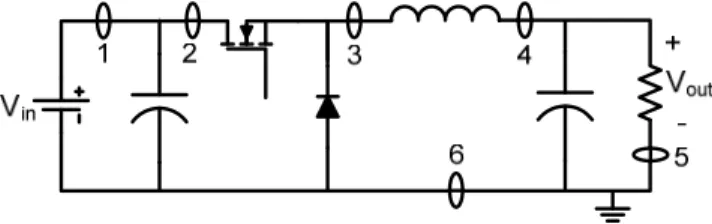
Figure 1.1. Possible current sensing locations in typical power switching stage
Sensing location 1 is good for sensing total input current (dc and ripple), which is required for power factor control, short circuit protection, and input power calculations. Sensing location 2 measures the switch current. It is a good location for peak current-mode control and overall short circuit protection. Sensing location 3 gives average current information. This location is not effective due to the wide voltage swing. Sensing location 4 gives information about both instantaneous inductor current and average load current, which are useful for average current-mode control. Sensing at location 5 is easier than all of the locations discussed above. This location yields true information about the output current. However, this information is not useful for short circuit protection. Grounding will affect the regulation at this location because the voltage across sensing element needs to be subtracted from the output voltage Vout. The problem with location 6 is the separation of load grounding from the input.
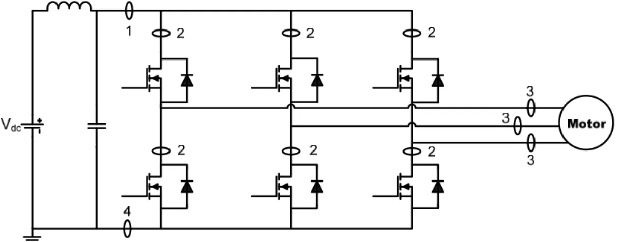
In motor drives systems, protection and control are implemented by measuring the current at different positions, as shown in Figure 1.2. Sensing location 1 protects the motor inverter by measuring the input current. Sensing location 2 protects the semiconductors by direct current measurement. Sensing location 3 effectively senses the motor current as a part of the speed control system. Sensing location 4 detects the dc link current and polarity to protect semiconductor devices.
Figure 1.2. Possible current sensing locations in motor drives
1.7. THESIS ORGANIZATION
In this thesis, several current sensing techniques have been reviewed and evaluated which are different in accuracy, complexity, cost, operating range, linearity, current magnitude, bandwidth, electric isolation, switching noise sensitivity, and ac response. Different resistive-based current sensing methods are presented in Section 2. Section 3 discusses various electromagnetic-based current sensing techniques. Section 4 provides information about different current sensing techniques with self-tuning and/or self-calibration. Average current sensing techniques are discussed in Section 5. At the end of each Section, all of the current sensing techniques presented in the Section are compared. Finally, Section 6 presents an overall evaluation of current sensing techniques.
2. RESISTIVE-BASED CURRENT SENSING TECHNIQUES
According to Ohm’s law, when current is flowing through a resistor, there is a voltage drop across it. Therefore, a resistor can be used to measure the current in a circuit and translate it into a voltage. This voltage signal is a representation of the current, which can be easily measured and monitored by control circuitry. The sense resistor, the resistor used for current measurement, must have low resistance to minimize its power consumption [39].
2.1. RESISTIVE-BASED CURRENT SENSING TECHNIQUE USING AN EXTERNALLY ADDED SENSE RESISTOR
A current detecting circuit of a dc-dc converter using an external sense resistor Rsense is shown in Figure 2.1. Rsense acts as a current to voltage converter.
Figure 2.1. Current sensing using an externally added sense resistor
Discrete resistor and PCB trace are the most common types of Rsense [40-44]. If Rsense value has tight tolerance, this technique is accurate for low current values. When resistor Rsense is crossed by inductor current IL in a buck converter, current IL is sensed by
measuring the voltage (Vsense) across sense resistor Rsense, as depicted in Figure 2.1. Current IL is given by (2.1). sense sense L
R
V
I
=
(2.1)Due to its simplicity and accuracy, this method is used for power factor correction and over current protection. The criteria for the selection of Rsense are voltage drop, accuracy, efficiency and power dissipation, parasitic inductance, and cost. The drawback of this technique is the power loss incurred by resistor Rsense. Therefore, this method is inefficient for dc-dc converters. Additionally, it does not provide measurement isolation from transient voltage potentials on the load. A noise filter is required to reduce the noise in the signal output, which will affect the overall system bandwidth. This technique is not applicable to high performance dc-dc converters whose efficiency requirements are more than 85-90%.
If resistor Rsense is placed on the load side (see Figure 2.1), it only gives information about the output current. Input current measurement is required to achieve adaptive voltage positioning in voltage regulators. Input current sensing is achieved by placing Rsense on the input side. A modified metal oxide semiconductor (MOS) current sensing technique using a current mirror to overcome power loss incurred by sense resistor is presented in [45]. This method measures the current without requiring the entire output current to pass from the series sense resistor. This technique uses the microelectronic current mirroring concept. The current passing through the sense resistor is proportional to the output current and its magnitude is smaller.
2.2. RESISTIVE-BASED CURRENT SENSING TECHNIQUE USING THE INTERNAL RESISTANCE OF AN INDUCTOR
To avoid the use of sense resistor and to reduce the power loss it creates, an inductor is used for current sensing, as depicted in Figure 2.2 [38]. This method is appropriate for low voltage power converters. Resistor RL in series with inductor L is the internal resistance or direct current resistance (DCR) of the inductor winding.
V2 to IL Converter V1+V2 V1 V2 IL Vin + + -+ L RL IL
Figure 2.2. Current sensing using the internal resistance of an inductor
The voltage across the main inductor is made of two voltages V1 and V2, which are given by (2.2). L L L L
I
R
dt
dI
L
V
V
V
=
1+
2=
+
(2.2)An extra winding with an equal number of turns and minimum current loading is coupled with the main inductor, as shown in Figure 2.2. The voltage across the extra winding is V1 due to the equal number of turns. If the voltages of both windings are added, the resulting voltage is simply ILRL drop. The disadvantage of this technique is that the measured current is inaccurate because V2 which is the difference between two
large voltages is quite small. Inductor winding is built by copper wire, so, the temperature coefficient of copper’s resistivity also applies.
2.3. MOSFET RDS-BASED CURRENT SENSING TECHNIQUE
A lossless MOSFET drain-source resistor-based current sensing method, which eliminates the need for resistor Rsense for current sensing, is depicted in Figure 2.3 [46-49]. The drain-source resistance (RDS) of the MOSFET is useful for current measurements. A MOSFET acts like a resistor when it is on, so it is possible to determine current IL by measuring the drain-source voltage of the switch.
Figure 2.3. MOSFET RDS-based current sensing
Current IL can be determined by measuring switch current IS. As switch S is on in a buck converter during the time interval 0<t<dT only, a sample-and-hold circuit is required to sense current IL. Current IS is determined by measuring the voltage across resistor RDS. Current IS is given by (2.3).
DS sense L S
R
V
I
I
=
=
(2.3)A MOSFET is in the triode region when it is conducting and voltage across it is low. MOSFET acts like a resistor in this case. The resistance RDS is given by (2.4).
(
in T)
OX DSV
V
C
W
L
R
−
=
µ
(2.4)Where µ is the electron mobility, Cox is the oxide capacitance, and VT is the threshold voltage. The value of resistance RDS is given in the MOSFET data sheet. The accuracy of this method depends on the tolerance of resistor RDS. The datasheet gives only the maximum and typical values of resistor RDS, not the minimum.
MOSFET RDS-based current sensing is a very low cost method for current sensing. One of the uses of this method is in low-voltage, high-current point of load converter applications. However, the actual current threshold will vary with resistance RDS. Resistance RDS varies with temperature, gate drive voltage, and individual devices. Variations in the gate drive amplitude result in a poor current sensing accuracy in multiphase converters. Higher switching frequencies and higher input voltages make this method complicated.
2.4. CURRENT-SENSING POWER MOSFET-BASED CURRENT SENSING TECHNIQUE
Current-sensing power MOSFET technique is more accurate than the MOSFET RDS-based current sensing technique [50-57]. A power MOSFET consists of a large number of parallel connected MOSFET cells. The gates, sources, and drains of all transistor cells are connected together. However, when power MOSFET is tuned on to sense the current, the entire amount of the sense current passes through sense resistor, so there is a significant and undesirable power loss. To avoid this power loss, few cells in
the power MOSFET are utilized to provide sensing FET (SENSEFET). Remaining transistor cells are used to provide the switching MOSFET. This new power MOSFET structure is known as a current-sensing power MOSFET. The current-sensing power MOSFET is a parallel connection of a SENSEFET (S2) and switching MOSFET (S1), as shown in Figure 2.4. Switch S2 has relatively fewer transistor cells to provide a small sensing signal proportional to the switch S1 current. A sense resistor is placed on the scaled down current to reduce the power dissipation; therefore, this technique is used to provide accurate and lossless current measurement. A current-sensing power MOSFET is symbolically represented in Figure 2.4.
Figure 2.4. Current-sensing power MOSFET
The current-sensing power MOSFET is a five terminal device. Switches S1 and S2 have identical unit cell structures and reside on the same silicon substrate. Their gate terminals are connected to a common terminal G and their drain terminals are connected to a common terminal D. Source terminals of switch S2 are connected to a current sense or mirror terminal S and source terminals of switch S1 are connected to a main terminal
M which consists of Kelvin-sense terminal K and source terminal S. A Kelvin-sense terminal is shorted internally to the source terminal of switch S1 to bypass the packaging and interconnection parasitic resistance associated with switch S1. It provides more accurate current sensing.
The most common practice of using S1 and S2 for current sensing in a buck converter is shown in Figure 2.5. N is a predetermined ratio of the transistor cells of switch S1 to switch S2. For example, N may be in the order of 100 to 1000. If N increases, accuracy of the circuit decreases. All transistor cells of the current-sensing power MOSFET are similar; therefore, if the sources of switches S1 and S2 are virtually connected, switches S1 and S2 pass currents in the ratio N:1, and have resistances in ratio 1:N.
Figure 2.5. Current-sensing power MOSFET-based current sensing
An operational amplifier in Figure 2.5 is used to make the gate-to-source voltages of both switches equal. Since only a predetermined fraction of total current is passing
through Rsense, power dissipation in Rsense is low. As current passing through S1 is not continuous, a sample-and-hold circuit holds the sensed current when S1 is off. The sense voltage Vsense in this technique is given by (2.5).
= N I R V L sense sense (2.5)
The use of current-sensing power MOSFET is impeded by its limited availability and high cost. This method is not applicable to high frequency systems because it introduces switching transients and noise to the sense signal. The accuracy of this method is limited because it works only when switches S1 and S2 are matched. Because this technique’s current ratio is N:1, a low degree of coupling between S1 and S2 can induce a significant error and large spikes are injected in the sense signal during high di/dt periods.
2.5. PWM-VSI SWITCHING STRATEGIES
For the purpose of motor current sensing, the switching strategies of an inverter are discussed in this sub-section, assuming its load is a three phase star connected motor. However, the same reasoning is applied to single phase or poly-phase and star or delta connected synchronous or asynchronous motors.
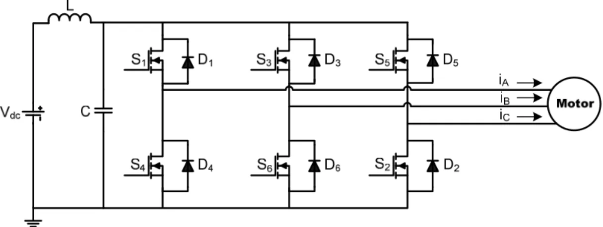
PWM techniques are used in voltage source inverters (VSI) to control different types of motors. A three phase PWM-VSI driven ac motor is depicted in Figure 2.6. All three legs of an inverter are supplied by a dc voltage source. A large capacitor connected at the input terminals tends to make the input dc voltage constant and suppresses the harmonic fed back to the source. A control signal is provided through the gate of each transistor.
Figure 2.6. PWM-VSI driven ac motor
Switches in VSI are numbered in the sequence in which they are triggered. Three phase VSI works with either 180° or 120° conduction mode [58, 59].
If three phase VSI works with 180° conduction mode, switch pairs S1, S4; S3, S6; and S5, S2 are turned on with a time interval of 180°, which means S1 conducts for the first 180° and S4 for the next 180° of a cycle, as shown in Figure 2.7.
Figure 2.7. Switching sequence of a 180° VSI conduction
Switches in the upper group, i.e, S1, S3, and S5, conduct at an interval of 120°, which implies that if S1 is fired at angle 0°, then S3 must be fired at angle 120° and S5 at
angle 240° [59]. Each arm of a three phase VSI has three possible states, so a total of twenty-seven combinations are possible. Only eight states that do not involve both transistors of any phase to be on at once are used. During remaining nineteen states the phase voltage depends on the conduction of freewheeling diodes. Eight different states of six switches are given in Table 2.1 for 180° VSI conduction. A simple logic circuit is required to identify states 1-6 of Table 2.1. Control signals are then fed to the inverter. However, control signals provided to the upper legs of inverter are opposite to the control signals provided to the lower legs.
Table 2.1. Different states of a 180° VSI conduction
State S1 S2 S3 S4 S5 S6
0 off on off on off on
1 on off off off on on
2 on on off off off on
3 on on on off off off
4 off on on on off off
5 off off on on on off
6 off off off on on on
7 on off on off on off
If three phase VSI works with 120° conduction mode, each switch conducts for 120° of a cycle, as shown in Figure 2.8. Like 180° mode, 120° mode VSI also requires six steps, each of 60° duration, to complete one cycle of the output ac voltage. The six different possible states of six switches are given in Table 2.2 for 120° VSI conduction.
Figure 2.8. Switching sequence of a 120° VSI conduction
Table 2.2. Different states of a 120° VSI conduction
State S1 S2 S3 S4 S5 S6
1 on off off off off on
2 on on off off off off
3 off on on off off off
4 off off on on off off
5 off off off on on off
6 off off off off on on
2.6. CURRENT SENSING TECHNIQUES FOR PWM-VSI DRIVEN AC MOTOR USING EXTERNALLY ADDED SENSE RESISTORS
Different current sensing strategies for measuring motor current using externally added sense resistors are described in this sub-section.
2.6.1. An Externally Added Sense Resistor in Each Leg of the Inverter. For certain applications, the current must be measured in individual legs of the motor controller inverter for various purposes. A VSI with current sensors in the three low side inverter switches to achieve closed-loop current regulation is shown in Figure 2.9. Sense resistors are used to sense the current flowing through each leg of the motor controller circuit [60-62]. Sense resistors are connected to the source pin of each low side transistor.
Figure 2.9. Motor current measurement using an externally added sense resistor in each leg of VSI
When VSI operates with 180° conduction, at any given instant of time all three motor phases carry currents. Therefore, when two lower leg switches are on, two of the three motor phase currents are determined by measuring the voltages developed across Rsense (Vsense) to obtain complete motor line current information. For instance, if switches S1, S6, and S2 are on, voltages developed across resistors Rsense are measured to determine currents iB and iC. Using the information about currents iB and iC, it is easy to calculate current iA. However, the current measured by this technique is the half bridge current not the motor phase current, as shown in Figure 2.9. Sample-and-hold circuit is required to reconstruct the motor phase current.
In order to get a good sample of voltage Vsense for current measurement, the width of lower leg pulse must be long enough. However, if lower transistors are turned on for a high portion of PWM period, it will create noise problems for the entire sense output sampling circuit due to high dv/dt and di/dt.
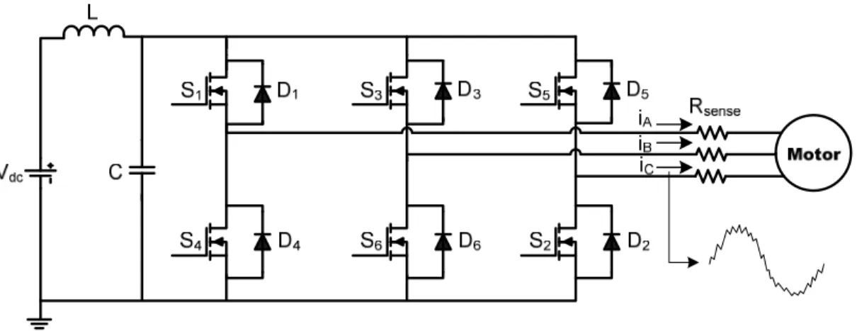
2.6.2. Externally Added Sense Resistors in Series with Motor Phases. In this method, the sense resistors are connected in series with motor phases, as depicted in Figure 2.10 [63, 64]. The voltage drop across each resistor is measured to determine the current flowing through each phase. Also, at any given instant of time in this method, only two phase currents need to be measured to get full information about motor line currents.
Figure 2.10. Motor current sensing using externally added line sense resistors
This method’s major disadvantage is that the measured current has a common mode rejection problem because the small common mode signal with fast dv/dt rides on top of the measured current, as shown in Figure 2.10. A common method of solving the common mode rejection problem is to use an optically coupled isolated amplifier. However, if resistance is small when measuring higher currents, the inductive component of the impedance begins to dominate.
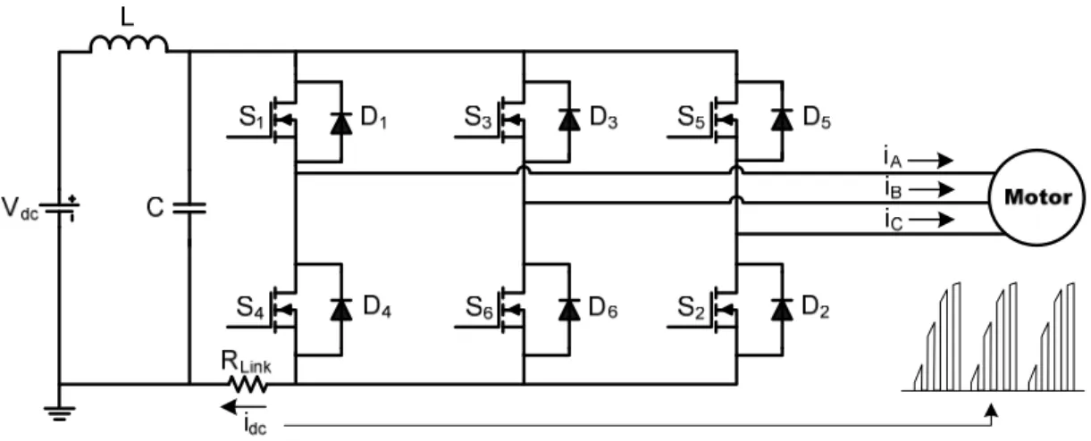
2.6.3. An Externally Added Sense Resistor with DC Link. Depending on the states of transistor switches and period of operation, the current through the motor phases can be measured or calculated by a single resistor, as shown in Figure 2.11. In the dc link sense resistor method, a single resistor is placed on the dc link between the dc power supply and the inverter to avoid level shifting during current measurement [65-78]. The dc link sense resistor minimizes the cost and power dissipation.
Figure 2.11. DC link current sensing using an externally added sense resistor
In ac drive systems, as mentioned earlier, if VSI works with 180° conduction, current Idc is equal to one of the motor phase current or opposite to it for six different states, as depicted in Table 2.3. Idc is zero when the upper three switches are on and the lower three switches are off or vice versa. If VSI works with 120° conduction, at any given instant the phase currents are expected to flow in only two phase windings (the third phase current is zero). Only one current measurement is necessary in the dc link and
other phase motor current can be reconstructed from dc link current information as depicted in Table 2.3.
It is also possible that the machine winding currents circulate within the VSI with some switching strategies, so there is no current available in the dc link for measurement. Furthermore, the measured current is the total bus current, not the phase current, as shown in Figure 2.11. The phase currents are reconstructed using measured dc link current and the knowledge of the switching states [78].
Table 2.3. DC link current for a PWM-VSI driven motor with 180° and 120° conduction State idc for 180° Conduction idc for 120° Conduction
1 -iB iA = -iB 2 iA iA = -iC 3 -iC iB = -iC 4 iB iB = -iA 5 -iA iC = -iA 6 iC iC = -iB
No switch status information is needed in the inverter for current measurement if the sense resistor is connected to the positive rail of the VSI. However, the inverter circuit becomes more complicated to avoid reverse current flow into the sense resistor. The voltage information at two points of Rsense is required to find the voltage drop across Rsense in this method, whereas voltage measurement at only one point is required when Rsense is connected to the negative rail. It is also possible to connect the dc link sense resistor between the dc source and the capacitor, rather than between the capacitor and the inverter on the negative rail.
2.7. MOSFET RDS-BASED CURRENT SENSING FOR PWM-VSI DRIVEN AC
MOTOR
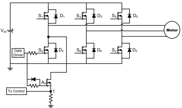
A MOSFET switch has a linear resistance characteristic when it is on. Therefore, when the MOSFET switch is on in VSI, it is possible to get the motor current information from voltage drop observed across it. The circuit used to sense the single motor phase current by measuring the low side MOSFET switch (S4) voltage is depicted in Figure 2.12 [79]. The other two phases are exactly the same.
Motor S1 D1 S4 D4 S3 D3 S6 D6 S5 D5 S2 D2 Vdc Gate Driver A4 1 To Control
Figure 2.12. MOSFET RDS-based current sensing technique for motor current detection
When low side MOSFET switch S4 is on, switch A4 also turns on, and the voltage at point 1 is the same as the voltage drop across switch S4. When MOSFET switch S4 is off, switch A4 also turns off, and the voltage at point 1 is zero. If the voltage drop at point 1 and resistance RDS of switch S4 are known, it is easy to derive the motor phase current
passing through switch S4. The current information obtained from this technique is useful for current protection purposes; hence variation in RDS is acceptable.
2.8. CURRENT-SENSING POWER MOSFET-BASED CURRENT SENSING TECHNIQUE FOR PWM-VSI DRIVEN AC MOTOR
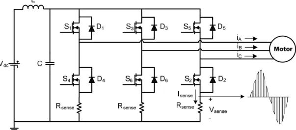
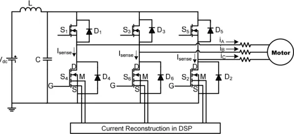
A technique for phase current measurement in VSI using current-sensing power MOSFET is depicted in Figure 2.13 [80-88]. In this method each of the three lower leg MOSFET switches in VSI are replaced by current-sensing power MOSFETs. Current-sensing power MOSFET enables accurate and low cost current measurement. These current sensors are designed to accurately mirror the motor phase current.
Figure 2.13. Current-sensing power MOSFET-based current sensing technique for motor current detection
A limitation of this technique is that its ability to measure the current only when the current flowing through it is in a forward direction, which is only possible when the polarity of the phase current is negative. Another limitation is that, at each particular
instant, two lower leg switches need to be on for complete current measurement. However, the current measurements taken using this technique are incomplete because the output phase current passes through the low side switch for only half of the fundamental cycle. Therefore, the alternating 60° intervals (three times during each fundamental frequency cycle) provide incomplete current information. A technique is depicted in [82] to reconstruct the three phase currents during the intervals when they are not measured.
It is also possible to connect the current sensors to the upper leg of VSI, but it requires high performance level shifting to transfer the sensed signal to a common reference. On the contrary, if the current sensors are in the lower leg of VSI, they can share the same reference terminal, simplifying the signal conditioning.
2.9. COMPARISION BETWEEN RESISTIVE-BASED CURRENT SENSING TECHNIQUES
Table 2.4 summarizes the advantages and disadvantages of the presented resistive-based current sensing techniques.
Table 2.4. Comparative overview of resistive-based current sensing techniques
Techniques Advantages Disadvantages
Using an externally
added resistor Simple, accurate, low cost Power loss incurred by sense resistor Using the internal
resistance of an inductor
Accurate, lossless Not useful for high power applications
MOS current sensing Lossless, accurate Complicated circuit, accuracy depends on
matching performance of the current mirror Using the internal
resistance of a MOSFET
Lossless, no additional sensing component required, low cost
Not accurate for high input voltage and high switching frequency, affected by temperature
variations of RDS, discontinuous and noisy
Using current-sensing power
MOSFET
Lossless, practical, accurate with respect to temperature variations, no additional sensing component required,
low cost
Special MOSFET, introduce switching transients and noise at high frequency, accuracy depends on matching performance of the current mirror, switching noise, limited
3. ELECTROMAGNETIC-BASED CURRENT SENSING TECHNIQUES
Resistive-based current sensors are acceptable where power loss, low bandwidth, noise, and non isolated measurement are acceptable. These sensors are not used in high power applications where isolation is required. Solution to these problems is electromagnetic-based current sensing techniques.
Based on Ampere’s law, the current flowing through a conductor generates magnetic field. Hence, sensing the magnetic field surrounding a conductor provides information about its current. Electromagnetic-based techniques work based on this phenomenon while they provide galvanic isolation between the control and power stages, higher bandwidth, and lower power losses. The lower power dissipation of electromagnetic-based current sensors allow much higher signal level, significantly improves the signal-to-noise environment of the control system [39].
3.1. CURRENT MEASUREMENT TECHNIQUES USING CURRENT TRANSFORMERS
A current transformer (CT) is similar to a voltage transformer; except that the primary input is a current. There are four basic types of CTs [89-92]: ac current transformers (ACCTs), unidirectional current transformers (UCTs), dc current transformers (DCCTs), and fly-back type current transformers (FBCTs). ACCTs and UCTs are commonly used, DCCTs are used for high current applications, and FBCTs are used when current pulses are very short.
CTs are used with low range ammeters to measure currents in high voltage circuits. In addition to providing insulation from the high voltage side, CTs step down the
current in a known ratio. Their physical basis is the mutual induction between two circuits linked by a common magnetic flux. A CT consists of two inductive coils, which are electrically separated but magnetically linked through a path of low reluctance, as shown in Figure 3.1. If one coil is connected to an ac source, an alternating flux is set up in the core, most of which is linked with the other coil in which it produces mutually induced electromotive force (EMF) according to Faraday’s law of electromagnetic induction. The first coil is called the primary coil, and second coil is called the secondary coil of the CT. If the secondary of the CT is closed, electric energy is magnetically transferred from primary to secondary.
Figure 3.1. Current transformer
For an ideal transformer with no load, the induced secondary EMF is same as the secondary terminal voltage (VS). The relationship between the primary and secondary voltages, currents, and number of turns is given by (3.1).
S P P S S P
N
N
I
I
V
V
=
=
(3.1)Where VP and VS are primary and secondary terminal voltages, IP and IS are primary and secondary winding currents, and NP and NS are the number of primary and secondary turns, respectively.
For typical switching converter applications, a CT has single turn primary and multi-turn secondary. The basic CT schematic is given in Figure 3.2.
Figure 3.2. Basic circuit of single turn primary current transformer
The primary is formed by wire from which an unknown current is passing. The secondary has large number of turns and it is terminated by terminating or burden resistor (Rt). If the number of secondary turns is too large, then there will be a significant inter-winding capacitance (CW). In addition to primary and secondary windings, capacitance CW is also added in the model of a CT.
The relationship between currents IP and IS in this case is given by (3.2).
S P S
N
I
I
1
=
(3.2)Capacitor CW is not considered here since the measured frequency is low. The secondary output voltage (Vsense) in a CT is proportional to the resistor Rt based on the current flowing through it. Voltage Vsense across the secondary is given by (3.3).
t S P t S sense
R
N
I
R
I
V
=
=
(3.3)One of the most commonly used CTs is known as clamp-on or clip-on type. It has a laminated core which is arranged in such a manner that it can be opened by pressing a switch, permitting the admission of the current carrying conductor. The current carrying conductor acts as a single turn primary, whereas secondary is connected across the standard ammeter.
CTs are used in control and limiting applications. The advantages of a CT include good signal-to-noise ratio (SNR), galvanic isolation between control circuit and the line being monitored, good common mode rejection, high bandwidth (50 or 60 Hz to 20 kHz), and low power loss in high-current applications. Galvanic isolation is required to protect the sensing device from high power signals and to reduce the power dissipated by the sensing resistor. The secondary side current can be made smaller by using a larger turns ratio. CTs are relatively simple to implement and are passive devices that do not require driving circuitry for operation. The major disadvantages of CTs are their higher cost, larger size, and non-integrality. An ACCT gets saturated if input is direct current. Yet, some methods are used to sense the switch dc current in switching power converter using CTs. It is due to the fact that switch currents in the converter are interrupting, allowing time for transformer reset.
3.1.1. Using the Existing Inductor as the Primary of a Transformer. This technique measures the current flowing through an inductor by using existing inductor of a converter as the primary of a transformer. Primary current IL will generate magnetic field that is coupled into a secondary coil. As shown in Figure 3.3, in a buck converter, the inductor is used as the primary side of a transformer, and the secondary side develops voltage proportional to current IL [42].
Vsense L NP:NS Vout + -IL C R D Vin S1 Integrator ∫ + -1/L IL + VL
-Figure 3.3. Current measurement using the existing inductor as the primary of a transformer
Inductor current in this technique is calculated by (3.4). For integration it is necessary to know the value of inductance L.
dt
v
L
i
L=
1
∫
sense (3.4)This technique measures the fraction of the high inductor current. The transformer only passes the ac part of current IL, not the dc, and no information about average current is provided by technique. This technique is not appropriate for over current protection.
The presence of the dc current affects the low frequency performance of ACCT. In order to recover the dc component of the current signal during current measurement, the following techniques are used.
3.1.2. AC Current Transformer with Sample-and-Hold Circuit. The magnetic core of the ACCT needs to be optimized such that the ACCT is able to function with a primary current having a dc current component. One method of gathering full information about current IL in the buck converter is depicted in Figure 3.4 [93]. Two ACCTs, CT1 and CT2, are used to measure the two switch currents. Additional circuits are required to reconstruct the two switch current signals. Reconstructed current outputs of CT1 and CT2 are then added to obtain full information about current IL. Two blocks with gain NP/(NSRt) are required to adjust the different scaling used in the two CTs.
Vin IL R L S1 S2 + -Control Sample/ Hold Sample/ Hold + -C IL CT1 CT2 Vsense1 Vsense2 + t S P R N N t S P R N N
Figure 3.4. Inductor current estimation using two ac current transformers
Usually, CT1 and CT2 will filter off the dc component of the primary current, so they allow only the ac part on the secondary side. In order to obtain full information of current IL, additional sample-and-hold circuits are required for switch current
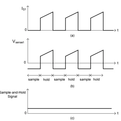
reconstruction, as depicted in Figure 3.4. Current sensor waveforms for CT1 are shown in Figure 3.5.
Figure 3.5. Current, voltage, and sample-and-hold circuit waveforms for CT1
Figure 3.5 (a) shows the ideal switch current (IS1) waveform for switch S1. The dc component of current IS1 is filtered off in the secondary voltage (Vsense1) of CT1 as shown in Figure 3.5 (b). However, no information is lost in this process. In order to obtain complete inductor current information in each cycle, sample the value of voltage Vsense1 when switch S1 is turned off, hold that value when switchS1 is turned on, as shown in Figure 3.5 (c). The output of the sample-and-hold circuit is deducted from the voltage Vsense1 to get a signal which is proportional to current IS1. Current through switch S2
(Isense2) is estimated in the same manner as with switch S1. Two switch current signals are added to estimate IL. High bandwidth sample-and-hold IC is required in this method.
There are some design requirements for the ACCT core in this method. For CT, if H is the magnetic field intensity and l is the magnetic mean path, then according to Ampere’s law, the magneto-motive force (MMF) is given by (3.5).
Hl
I
N
I
N
P P+
S S=
(3.5)If
φ
is the total flux, B is flux density, A is the cross sectional area of the core,o
µ
is the vacuum permeability,µ
ris the relative permeability, and Re is the reluctance of the magnetic circuit, (3.5) can be rewritten as (3.6).φ
µ
µ
φ
µ
µ
r r e S S P Pl
R
A
l
B
I
N
I
N
+
=
=
=
0 0 (3.6)According to Faraday’s law of electromagnetic induction, the secondary voltage is given by (3.7).
dt
d
N
R
I
V
sense=
S t=
Sφ
(3.7)From (3.6) and (3.7), ratio of currents IS and IP is given by (3.8).
+
−
=
ks
N
N
I
I
S P P S1
1
1
(3.8)Where k is given by (NS2) /(Rt Re). Corner frequency (fC) of low pass filter is specified by (3.9). 2
2
2
S e t CN
R
R
k
f
=
π
=
π
(3.9)The first design requirement is that the fC needs to be much lower than the switching frequency (fS). The second design requirement is that the CT does not get saturated in its operation. More information about this requirement is discussed in detail in [3].
This technique has low power loss, fast response, and is accurate. It is also possible to obtain IL by only measuring the high side switch S1 current. A suitable analog circuit is required to connect the maximum and minimum points of the switch S1 current to obtain full information about current IL. The circuit required for that method is quite complicated.
3.1.3. Current Measurement using AC and Unidirectional Current Transformers. The magnetic flux in a typical ac transformer core alternates between positive and negative values, but not in the UCT. The UCT operates in a unipolar mode. For UCT, the core should have two properties; high permeability and low remanence.
The basic UCT circuit is shown in Figure 3.6 [94-97]. When a positive current pulse IP flows in the primary of UCT, diode D conducts. Output voltage Vsense developed across resistor Rt is given by (3.3), and current IS in this is given by (3.10).
M S P S
I
N
I
I
=
−
(3.10)Capacitor CW is not considered here since frequency is low. Diode D will block the zero primary current and capacitor C will resonate with magnetizing inductor LM to develop a negative half cycle sinusoidal pulse across secondary winding to reset the magnetizing current (IM). Current IM has a small value due to this cycle by cycle reset. This provides a fast reset for the transformer core, and isolates the negative reset voltage from the control circuit. Capacitor Cf is a filtering capacitor required for suppressing high frequency noise.
Figure 3.6. Basic circuit of a unidirectional current transformer
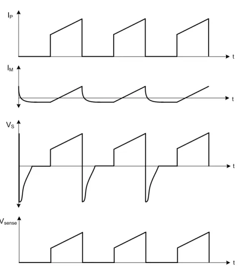
Waveforms for currents IP and IM and voltages VS and Vsense of a UCT are given in Figure 3.7. During the pulse duration of current IP, diode D conducts. The current IS in Rt will be a transform of current IP, and an analogue voltage of primary current will be developed across Rt. At the end of the conduction pulse, rapid UCT core recovery occurs because D blocks the reverse voltage across Rt. As a result, voltage VS is large, enabling fast core restoration between pulses. For accurate current measurement by UCTs, inductance needs to be large to reduce current IM. Current IM increases during the pulse
duration. At the end of the conduction period, current IM needs to be smaller than current IP. IM t t IP VS t t Vsense
Figure 3.7. Unidirectional current transformer waveforms
A buck converter with UCTs and ACCT for current measurement is illustrated in Figure 3.8. The inductor current IL and the output current IO in any PWM converter are the combinations of the switch current IS, the diode current ID, and the capacitor current
IC. These currents are ac or zero return pulse, which can be measured by using ACCTs and UCTs.
Figure 3.8. Current sensing using unidirectional and ac current transformers
In a buck converter IL is given by (3.11).
D S
L
I
I
I
=
+
(3.11)UCT1 and UCT2 are used to measure IS and ID, as depicted in Figure 3.8. Current IL is then derived from the information of the measured currents. Current IC can be measured by using ACCT. Current IO is derived from the information of currents IL and IC. In a buck converter, current IO is given by (3.12).
C L
O
I
I
I
=
+
(3.12)This method is also useful for converters with isolation transformers. However, UCT has some limitations. There is no enough time for UCT to complete half cycle resonant reset at very high switching frequencies or very high or low duty cycles. The dc
magnetizing current in the transformer core will increase with a decrease in reset time. As a result, the dc level of the UCT output will drop.
3.1.4. DC Current Transformer. DCCT is used to accurately measure the dc current with low power loss. There are several different types of DCCT, one of which is shown in Figure 3.9 [98-100]. The secondary signal of DCCT is directly related to absolute value of primary current.
Rsense Vsense
AC
IP
IS
Figure 3.9. Current measurement using dc current transformer
DCCT has two ring cores, as depicted in Figure 3.9. AC supply is applied across their secondary to generate opposite polarity flux in each core, which will drive cores into and out of saturation. As each core comes out of saturation, the flux change induces a current IS that is proportional to the current IP. The rectifier is used to rectify the secondary signal. More information about this technique is given in [100].
3.2. CURRENT MEASUREMENT TECHNIQUES USING AIR CORE
The performance of a CT is often limited by the characteristics of its magnetic core material (hysteresis, non-linearity, losses, saturation, remanence (residual flux));
therefore, the design of an air core or coreless transformer is often considered. The challenge with air core current measurement techniques is to have enough measurement sensitivity and to be insensitive to external magnetic fields.
3.2.1. Rogowski Coil Current Sensor. The Rogowski Coil is a simple, inexpensive and accurate approach for current measurement. Structure of a Rogowski Coil is similar to a CT. However, instead of an iron core, Rogowski Coil is based on air or ironless bobbins with hundreds or thousand of turns, as shown in Figure 3.10. The Rogowski Coil has an air core, so it will never get saturated; therefore, its output of remains linear for high current measurement [101-106].
Figure 3.10. Rogowski Coil current sensor
The conductor from which the unknown current flows is surrounded by the Rogowski coil for current measurement, as shown in Figure 3.10. In order to place current carrying conductor inside, the Rogowski Coil can be opened without interrupting the circuit. The magnetic field produced by the current induces the voltage in the
secondary coil (E). Voltage E is proportional to the time derivative of current flowing through the conductor, which is given by (3.13).
dt
dI
M
E
*
P=
(3.13)Here, IP is the unknown primary current and M is the mutual inductance of the circuit. M depends on the geometric parameters of the coil and is given by (3.14).
l
AN
M
µ
o S=
(3.14)Where
µ
ois the permeability of free space, A is the cross sectional area of the coil, NS is the total number of secondary winding turns, and l is the mean path length of the coil. Because the derivative of the direct current is zero, the Rogowski Coil current sensor can not measure dc currents. It is used to measure ac or pulsed dc current only.The phase delayed secondary voltage is integrated to produce an output voltage (Vsense) which is proportional to current IP. If the Rogowski Coil is used to measure the current in a semiconductor switch, a simple resistor-capacitor integrator, as shown in Figure 3.10, can be used to reproduce current waveform as a voltage. Rogowski Coil terminals are connected in a special way to avoid the external field effects. The output voltage of the integrator circuit is given by (3.15), which is proportional to unknown current IP. P S sense