University of Bradford eThesis
This thesis is hosted in
Bradford Scholars
– The University of Bradford Open Access
repository. Visit the repository for full metadata or to contact the repository team
© University of Bradford. This work is licenced for reuse under a Creative Commons
Licence.
IP Mobile Multicast over Next Generation Satellite Networks
Design and Evaluation of a Seamless Mobility Framework for IP Multicast Communications over a Multi-beam Geostationary Satellite Network
Esua Kinyuy JAFF
Submitted for the Degree of Doctor of Philosophy
Faculty of Engineering and Informatics University of Bradford
i
ABSTRACT
Name: Esua Kinyuy JAFF
Title: IP Mobile Multicast over Next Generation Satellite Networks. Design and evaluation of a seamless mobility support framework for IP
multicast communications over a multi-beam geostationary satellite network.
Keywords: DVB, gateway handover, satellite handover, mobility management,
mobile multicast, IP multicast, PMIPv6, receiver mobility, source mobility.
The inherent broadcast nature of satellites, their global coverage and direct access to a large number of subscribers give satellites unrivalled advantages in supporting IP multicast applications. A new generation of satellite systems that support regenerative on-board processors and multiple spot beam technology have opened new possibilities of implementing IP multicast communication over satellites. These new features enable satellites to make efficient use of their allocated bandwidth resources and provide cost effective network services but equally, create new challenges for mobile satellite terminals. IP mobility support in general and IP mobile multicast support in particular on mobile satellite terminals like the ones mounted on continental flights, maritime vessels, etc., still remain big challenges that have received very little attention from the research community.
Up till now, there are no proposed mechanisms to support IP multicast for mobile receivers/sources in multi-beam satellite networks in open literature. This study explores the suitability of IP multicast mobility support schemes defined for terrestrial networks in a satellite environment and proposes novel schemes based on the concepts of Home and Remote subscription-based
ii
approaches, multiple interface and PMIPv6 protocol. Detailed analysis and comparison of results obtained from the proposed schemes, Mobile IP (MIP) Home and Remote subscription-based approaches (for terrestrial networks) when implemented on a reference multi-beam satellite network are presented. From these results, the proposed schemes outperform the MIP Home and Remote subscription-based approaches in terms of gateway handover latency, number of multicast packets lost and signalling cost over the satellite air interface.
iii
ACKNOWLEDGEMENTS
First and foremost, I wish to thank my supervisors Dr Prashant Pillai and Prof Yim Fun Hu, for their advice, encouragement and support during the course of this research work.
Notably, I wish to express my deepest gratitude to my dear wife, Juliana for her constant love, encouragement and cooperation throughout the duration of my study. My special thanks go to my two lovely children, Jesse and Janella for their understanding and support over the past four years.
Also, I wish to express my gratitude to Dr Muhammad Ali for his assistance in the development and simulation of the M3U-based approach using NS3.
Last but not the least, I wish to thank all members of the FUN Lab for their support and cooperation in one way or another during the course of my study.
iv
DEDICATION
In memory of my late father, Denis Tar Jaff
(15th April 1928 - 11th May 2011).
To my loving mother, Angelica Biy Jaff, who has been my source of inspiration and strength.
v
TABLE OF CONTENTS
ABSTRACT ... i ACKNOWLEDGEMENTS ... iii DEDICATION ... iv TABLE OF CONTENTS ... v LIST OF FIGURES ... x LIST OF TABLE ... xvLIST OF ACRONYMS ...xvii
1 INTRODUCTION ... 1
1.1 Satellite and multicast communications ... 1
1.2 IP multicast ... 3
1.2.1 IP multicast addressing ... 4
1.2.2 IP multicast protocols ... 4
1.3 IP multicast over next generation satellite networks ... 5
1.3.1 Star IP multicast ... 6
1.3.2 Mesh IP multicast ... 6
1.3.3 IP multicast protocols over satellite air interface ... 7
1.4 Motivation and problem statement ... 10
1.5 Aims and objectives ... 12
1.6 Contribution of the Thesis ... 13
1.7 Organisation of the Thesis ... 16
vi
2.1 The DVB-RCS/RCS2 network architecture ... 18
2.2 Interactive Satellite Network for Mobile Scenarios ... 22
2.3 Handovers in satellite networks ... 23
2.3.1 Beam handover ... 23
2.3.2 Gateway handover ... 23
2.3.3 Satellite handover... 24
2.4 Summary ... 25
3 IP MOBILE MULTICAST SUPPORT SCHEMES AND ADAPTATION TO THE SATELLITE ENVIRONMENT ... 26
3.1 IP mobile multicast problems ... 26
3.1.1 Mobile receiver problems ... 26
3.1.2 Mobile source problems ... 27
3.2 Current solutions to IP mobile multicast problems ... 28
3.2.1 Multicast receiver mobility support schemes ... 31
3.2.2 Hybrid - based approaches ... 46
3.2.3 Unicast /explicit multicast (Xcast)–based approaches... 47
3.2.4 Multicast source mobility support schemes ... 48
3.3 Summary ... 54
4 EVALUATION OF EXISTING IP MOBILE MULTICAST MECHANISMS OVER A MULTI-BEAM SATELLITE NETWORK ... 55
4.1 Good candidate schemes suitable for satellite environment ... 55
vii
4.3 Analytical mobility modelling for mobile IP multicast receivers ... 60
4.3.1 Using MIP HS-based approach ... 61
4.3.2 Using MIP RS-based approach ... 66
4.4 Analytical mobility modelling for mobile IP multicast sources ... 69
4.4.1 Gateway handover (GWH) with HA at GWs ... 70
4.4.2 Gateway handover (GWH) with HA at OBP ... 72
4.5 Results from analytical mobility modelling ... 73
4.5.1 Handover latency ... 75
4.5.2 Number of packets lost due to handover latency and satellite capacity required for retransmission ... 76
4.5.3 Signalling cost ... 79
4.5.4 Packet delivery cost for source mobility ... 81
4.5.5 Significance of the results ... 82
4.6 Summary ... 83
5 PROPOSED IP MULTICAST RECEIVER MOBILITY SUPPORT SCHEMES IN A MULTI-BEAM SATELLITE NETWORK ... 84
5.1 Satellite Home Subscription (SHS)-based approach ... 84
5.1.1 Gateway handover (GWH) in SHS ... 86
5.1.2 Satellite Handover (SH) in SHS... 89
5.1.3 Analytical mobility modelling for SHS-based approach ... 91
5.2 Satellite Remote Subscription (SRS)-based approach ... 93
viii
5.2.2 Satellite Handover (SH) in SRS... 95
5.2.3 Analytical mobility modelling for SRS-based approach ... 96
5.3 Multiple interface-based approach ... 97
5.4 PMIPv6-based approach ... 103
5.4.1 Scheme with MAG on ground segment (Layer 2 OBP) ... 104
5.4.2 Scheme with MAG on-board satellite (PMIPv6_DR_MAG_sat) .. 114
5.5 Comparison of the proposed IP multicast receiver mobility support schemes ... 120
5.6 Summary ... 122
6 PROPOSED IP MULTICAST SOURCE MOBILITY SUPPORT SCHEME IN SSM FOR A MULTI-BEAM SATELLITE NETWORK ... 124
6.1 The M3U-based scheme for source mobility support in SSM ... 124
6.1.1 M3U operation and processing ... 132
6.1.2 Uniqueness and importance of the proposed scheme ... 135
6.1.3 Analytical mobility modelling for M3U-based approach ... 135
6.2 Simulation of the M3U-based approach ... 136
6.2.1 Network simulator 3 (NS-3) ... 137
6.2.2 Implementation of M3U on NS-3 for source mobility support in SSM 137 6.2.3 Simulation architecture ... 140
6.2.4 Scenarios ... 141
ix
7 RESULTS, ANALYSIS AND DISCUSSION ... 144
7.1 IP multicast receiver mobility support schemes ... 144
7.1.1 Analytical results for satellites with transparent (or layer 2 OBP) payloads ... 145
7.1.2 Analytical results for satellites with layer 3 OBP payloads ... 159
7.1.3 Summarised comparison of IP multicast receiver mobility support schemes ... 164
7.2 IP multicast source mobility support schemes ... 165
7.2.1 Results from analytical mobility modelling ... 165
7.2.2 Results from M3U simulation ... 171
7.2.3 Summarised comparison of all IP multicast source mobility support schemes ... 175
7.3 Summary ... 176
8 CONCLUSION AND FUTURE WORK ... 177
8.1 Conclusion ... 177
8.1.1 IP multicast and satellite networks ... 177
8.1.2 IP mobile multicast and satellite networks ... 177
8.1.3 Summarised key novelties of the proposed schemes ... 178
8.1.4 Concluding remarks ... 182
8.2 Future work ... 183
x
LIST OF FIGURES
Figure 1.1 Star IP multicast topology [11] ... 6
Figure 1.2 Mesh IP multicast topology [11] ... 6
Figure 2.1 Satellite system operator roles ... 21
Figure 2.2 Gateway handover signalling sequence ... 24
Figure 3.1 Multicast receiver mobility support schemes [20, 25, 26] ... 31
Figure 3.2 MN joins group G via its HA in foreign network (FN1) – HS ... 33
Figure 3.3 MN in FN2 continues to receive multicast traffic via HA – HS ... 33
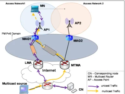
Figure 3.4 IP multicast deployment in PMIPv6 ... 36
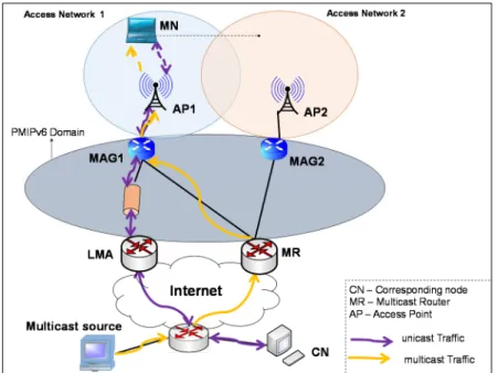
Figure 3.5 MTMA mode architecture for IP multicast receiver mobility support 40 Figure 3.6 DR mode architecture for IP multicast receiver mobility support ... 41
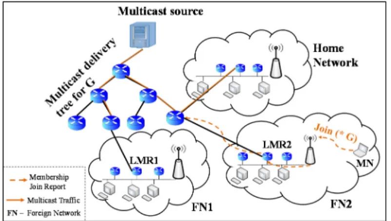
Figure 3.7 MN joins multicast group G via LMR1 in FN1 – RS ... 43
Figure 3.8 MN re-subscribes to multicast group G via LMR2 in FN2 ... 43
Figure 3.9 Current multicast source mobility support schemes ... 48
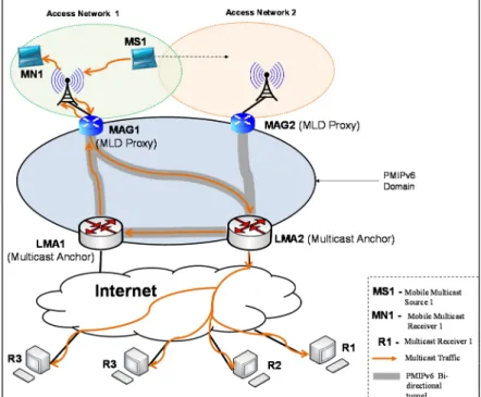
Figure 3.10 Base solution architecture for multicast source mobility support in PMIPv6 networks ... 50
Figure 3.11 Base solution call flow for multicast communication during MS1 handover in PMIPv6 domain [64] ... 52
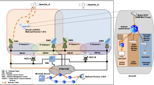
Figure 4.1 Reference network architecture for IP multicast mobility support over satellites ... 57
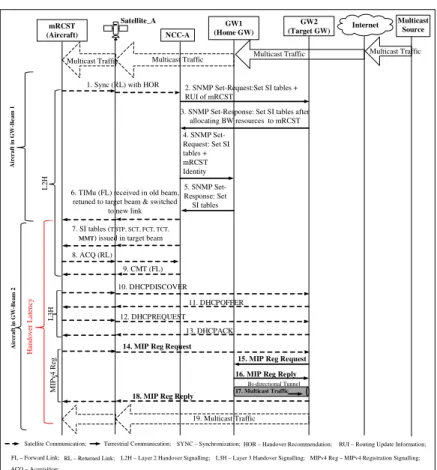
Figure 4.2 GWH signalling sequence for MIP HS-based approach – HA at GWs. ... 61
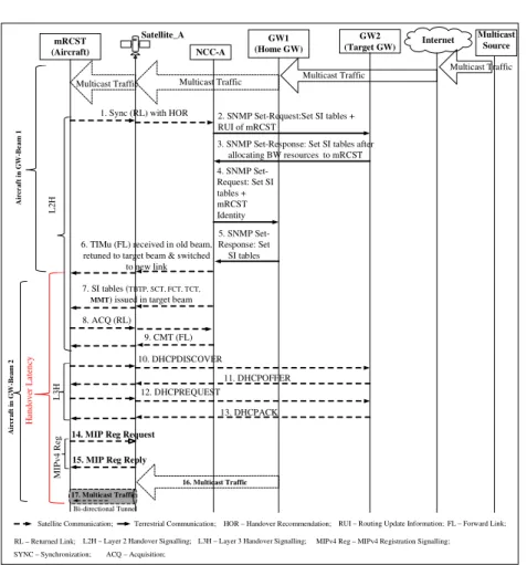
Figure 4.3 GWH signalling sequence for MIP HS-based approach – HA at OBP ... 63
xi
Figure 4.4 SH signalling sequence for MIP HS-based approach ... 64
Figure 4.5 GWH signalling sequence for MIP RS-based approach ... 67
Figure 4.6 SH signalling sequence for MIP RS-based approach ... 68
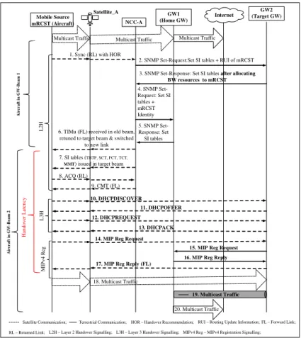
Figure 4.7 GWH signalling sequence for Source Mobility Support – MIP HS-based approach HA at GWs ... 70
Figure 4.8 GWH signalling sequence for Source Mobility Support – MIP HS-based approach HA at OBP ... 72
Figure 4.9 Comparison of GWH latency for HS- and RS-based schemes ... 75
Figure 4.10 Comparison of number of packets lost due to GWH latency satellite capacity required for retransmission ... 76
Figure 4.11 Comparison of signalling cost per GWH ... 79
Figure 4.12 Effect of varying satellite link weighting factor on total signalling cost per GWH for MIP HS-HA_GW scheme ... 81
Figure 4.13 Comparison of number of packet delivery cost before and after GWH for HS-based scheme... 81
Figure 5.1 SHS-based approach signalling sequence at GWH... 88
Figure 5.2 Aircraft now served by GW2 after GWH- SHS ... 88
Figure 5.3 SHS-based approach signalling sequence at satellite handover ... 90
Figure 5.4 Aircraft now served by GW3 after satellite handover- SHS ... 90
Figure 5.5 SRS-based approach signalling sequence at GWH... 94
Figure 5.6 Aircraft now served by GWA2 after GWH –SRS ... 94
Figure 5.7 SRS based signalling sequence at satellite handover ... 95
Figure 5.8 Aircraft now served by GW3 after satellite handover-SRS ... 95
Figure 5.9 Multi-homed mRCST for satellite interactive system... 98
xii
Figure 5.11 RCST logon signalling sequence ... 102 Figure 5.12 Satellite PMIPv6-based IP multicast receiver mobility support – MAG on Ground Segment ... 105 Figure 5.13 GWH signalling sequence for satellite PMIPv6-based IP multicast receiver mobility support – DR mode ... 107 Figure 5.14 Multicast delivery tree to aircraft (mRCST) after GWH - DR mode ... 107 Figure 5.15 GWH signalling sequence for satellite PMIPv6-based IP multicast receiver mobility support – MTMA mode ... 108 Figure 5.16 Multicast delivery tree to aircraft (mRCST) after GWH - MTMA mode ... 108 Figure 5.17 SH signalling sequence for satellite PMIPv6-based IP multicast receiver mobility support - DR mode ... 110 Figure 5.18 Multicast delivery tree to aircraft (mRCST) after SH - DR mode .. 110 Figure 5.19 SH signalling sequence for satellite PMIPv6-based IP multicast receiver mobility – MTMA mode ... 111 Figure 5.20 Multicast delivery tree to aircraft (mRCST) after GWH - MTMA mode ... 111 Figure 5.21 Satellite PMIPv6-based IP multicast receiver mobility support – MAG on-board satellite (s-MAG) ... 114 Figure 5.22 GWH signalling sequence for satellite PMIPv6-based IP multicast receiver mobility – MAG on-board satellite ... 117 Figure 5.23 SH signalling sequence for satellite PMIPv6-based IP multicast receiver mobility – MAG on-board satellite ... 118 Figure 5.24 Multicast delivery tree to aircraft (mRCST) after SH ... 119
xiii
Figure 6.1 Mobile IP multicast source (aircraft) at home network ... 125
Figure 6.2 Signalling sequence at GWH for the IP mobile multicast source ... 128
Figure 6.3 Mobile source now at foreign network (GW-B2) ... 131
Figure 6.4 M3U source mobility support processing for SSM during GWH ... 132
Figure 6.5 Block diagram of M3U implementation in NS-3 ... 139
Figure 6.6 Simulation scenario... 141
Figure 7.1 Comparing GWH latency for different IP multicast receiver mobility support schemes. ... 145
Figure 7.2 Effects of varying transmitter/receiver retuning time on GWH latency ... 147
Figure 7.3 Comparison of number multicast packets lost due to GWH latency for various schemes ... 148
Figure 7.4 Effects of varying average multicast session arrival rate (λs) on number of multicast packets lost due to GWH latency ... 150
Figure 7.5 Comparison of signalling cost per GWH and SH ... 150
Figure 7.6 Comparison of signalling cost over the satellite air interface per GWH/SH ... 153
Figure 7.7 Impact on total GWH signalling cost of varying speed ... 157
Figure 7.8 Impact on total GWH signalling cost of varying radius ... 158
Figure 7.9 GWH latency and GWH latency vs Tx/Rx for mobile receivers ... 159
Figure 7.10 Number of multicast packets lost/satellite capacity required for retransmission due GWH latency and effects of varying multicast session arrival rate (λs) on number of multicast packets lost per session ... 160
Figure 7.11 Comparing signalling cost and signalling cost over satellite air interface per GWH for the OBP schemes ... 162
xiv
Figure 7.12 Effects of varying speed of mRCST on total GWH signalling cost ... 163 Figure 7.13 Effects of varying radius of GW Beam on total GWH signalling cost ... 163 Figure 7.14 GWH latency and GWH latency vs Tx/Rx for mobile sources ... 165 Figure 7.15 Comparing total signalling cost and signalling cost over satellite air interface per GWH for source mobility support schemes ... 167 Figure 7.16 Effects of varying speed of mRCST on total GWH signalling cost - source mobility ... 168 Figure 7.17 Effects of varying radius of GW Beam on total GWH signalling cost – source mobility ... 169 Figure 7.18 Packet delivery cost per session and effects of varying multicast session arrival rate (λs) on multicast packets delivery cost per session ... 169
Figure 7.19 Average packet end-to-end delay for different scenarios. ... 171 Figure 7.20 Throughput and number of mobile sources ... 172
xv
LIST OF TABLE
Table 3.1 Comparison of the HS-based approaches ... 32
Table 3.2 Comparison of the RS-based approaches ... 42
Table 3.3 Comparison of the hybrid-based approaches ... 46
Table 3.4 Comparison of IP multicast source mobility support schemes ... 48
Table 4.1 Notation, message size and number of hops ... 74
Table 4.2 Comparison of GWH latency of MIP HS- HA_GW and the rest of the schemes considered. ... 76
Table 5.1 Binding cache entry (BCE) kept by LMA & s-MAG ... 116
Table 5.2 Comparison of proposed IP multicast receiver mobility solutions ... 121
Table 6.1 Proposed new messages ... 126
Table 6.2 Details of rx-table ... 138
Table 6.3 Details of src-table ... 139
Table 6.4 Details of mgroups-table ... 139
Table 6.5 Simulation parameters ... 141
Table 7.1 Notation and message size ... 144
Table 7.2 Reduction in GWH latency of the proposed schemes compared to MIP ... 146
Table 7.3 Reduction in signalling cost of the proposed schemes as compared to MIP ... 151
Table 7.4 Reduction in GWH signalling cost over the satellite air interface of the proposed schemes compared to MIP ... 155
Table 7.5 Comparison of IP multicast receiver mobility support schemes ... 164
Table 7.6 Summary of M3U simulation results ... 174
xvi
Table 8.1 Modifications to the LMA and MAG functions to suite the satellite environment ... 181
xvii
LIST OF ACRONYMS
ASM Any Source Multicast
ATN Aeronautical Telecommunication Network BCE Binding Cache Entry
BDMLSP Base Deployment for Multicast Listener Support in Proxy Mobile IPv6 (PMIPv6) Domains
BS Base solution for mobile source support in PMIPv6 networks CMT Correction Message Table
CNM CUM Notification Message CoA Care-of-Address
CUM Channel Update Message
DHCP Dynamic Host Configuration Protocol DR Direct Routing
DVB-RCS Digital Video Broadcasting - Return Channel via Satellite DVMRP Distance Vector Multicast Routing Protocol
FA Foreign Agent FL Forward Link
GEO Geostationary Earth Orbit GWH Gateway Handover HA Home Agent
HNP Home Network Prefix HS Home Subscription
IGMP Internet Group Management Protocol IP Internet Protocol
LLA Link-Local Address LMA Local Mobility Anchor
M3U Multicast Mobility Management Unit MAG Mobile Access Gateway
MI Multiple Interface MIP Mobile IP
MLD Multicast Listener Discovery
MMOFA Mobile Multicast Support using Old Foreign Agent
MMPMSHN Mobility Management Based on Proxy Mobile IPv6 for Multicast Services in Home Networks
MMROP Multicast Mobility Routing Optimizations for Proxy Mobile IPv6 MMT Multicast Map Table
MOSPF Multicast Extensions to Open Shortest Path First MR Multicast Router
mRCST Mobile Return Channel Satellite Terminal MS Mobile Source
MSA Mobility Support Agent MSS Mobile Satellite Services MTMA Multicast Tree Mobility Anchor NCC Network Control Centre NMC Network Management Centre NS-3 Network Simulator-3
OBP On-Board Processing/Processor PID Program Identifier
PIM-DM Protocol Independent Multicast - Dense Mode PIM-SM Protocol Independent Multicast - Sparse Mode
xviii
PMIPv6 Proxy Mobile IPv6
RCST Return Channel Satellite Terminal RL Return Link
RP Rendezvous Point RPF Reverse Path Forwarding RS Remote Subscription
RSGW Regenerative Satellite Gateway SH Satellite Handover
SHM Source Handover Message SHS Satellite Home Subscription SIUM Service Interface Update Message SI Table Service Information Table
S-MAG Satellite Mobile Access Gateway SNMP Simple Network Management Protocol SRS Satellite Remote Subscription
SSM Source-Specific Multicast TCP Transmission Control Protocol TIM Terminal Information Message Tx/Rx Transmitter/Receiver
1 INTRODUCTION
1.1 Satellite and multicast communications
Satellite communications is becoming a major player in the provision of mobile and ubiquitous communications especially in areas where terrestrial communication infrastructure is not present. Recent advancement in satellite technology has given birth to a new generation of satellite systems characterised by the support for multiple spot beams (frequency reuse), regenerative on-board processor (OBP) and the ability to utilise higher frequency bands (like the Ka-band, etc.). The presence of regenerative on-board packet processing implies that a full mesh, single-hop connectivity can be easily established between two or more satellite terminals/gateways compared to traditional ‘bent pipe’ satellite systems. Single-hop connectivity in mesh topology reduces the round trip delay by half compared to double-hop connectivity in star network topology. These new features are behind the huge increases in the satellite capacity, efficient utilisation of the allocated satellite bandwidth resources, support for high data rates and high-speed Internet access obtained in the new generation of satellite systems. While broadening the scope of satellite-based applications, these new features have also made satellite communications more competitive in the provision of services such as multimedia, integrated voice and data communications, etc., against other Internet-based communications technologies.
Considering the cost of satellite bandwidth resources, any technology that will efficiently utilize the available satellite bandwidth resources will be highly welcomed by both the satellite operators as well as satellite communication customers. This explains why IP multicasting which is a bandwidth saving technology is important to satellite networks. The unique ability of a satellite to
reach millions of customers while eliminating large numbers of intermediate routing hops presents an unrivalled platform for global deployment of group communications i.e., global IP multicast.
Unlike in broadcast, where the traffic is flooded in the whole satellite footprint, in IP multicast, traffic is only sent to spot beams that have at least one interested receiver, thus saving bandwidth in those spot beams that have no receivers. IP multicast applications that could be applicable to Mobile Satellite Services (MSS) like in long haul flights, global maritime vessels, continental trains, etc., include: on-demand multimedia content delivery (e.g., IPTV), real-time financial data, software distribution and upgrade, important service information like weather conditions, ongoing disaster zones and information, route updates, etc. With all these sets of new applications, next generation satellite networks with their support for fast Internet broadband have a unique opportunity to attract new customers and generate new revenues by deploying these new IP-based services. The aeronautical industry which is one of the key customers for mobile satellite services has recently adopted IP as the future network protocol for the Aeronautical Telecommunication Network (ATN) [1]. This opens up new opportunities for satellite-based IP multicast applications on mobile platforms as real-time important service information could be cost-effectively disseminated using IP multicasting, to a group of airlines in mid-air operating in a particular region or route or from an airline to a group of ground offices/emergency services around the world. So, IP multicast support in stationary as well as mobile customers (airliners, trains, ships, etc.) could bring significant financial savings due to the efficient utilization of the allocated bandwidth resources. For satellite operators, the bandwidth resources saved in each satellite footprint
could be made available to satisfy the existing customers’ demands or sell to new customers.
1.2 IP multicast
IP multicast is a network layer protocol which enables a sender to send a single copy of IP datagram simultaneously to a group of interested receivers which may be located at different destinations. Routers in the network layer play two key functions in IP multicasting:
• They ensure that only one copy of the same multicast traffic passes through
any particular network link by replicating multicast packets only when necessary at network branches leading to interested receivers.
• They use routing algorithms to figure out the optimal path to route packets
through various links to the interested receivers.
The advantage of IP multicast over unicast is that it saves processing overhead at sender’s network associated with sending duplicate copies to individual receivers and bandwidth overhead in the network since only one copy of the data traverses any network link leading to an interested receiver. Compared to broadcast in which the whole network is flooded with traffic, in IP multicast, traffic is sent to only network links that lead to an interested receiver. This reduces redundant traffic in the network, thus saving bandwidth resources compared to broadcast.
The fundamental concept of multicasting can be applied in three different layers of the Open System Interconnection (OSI) reference model namely: the Link layer, for Link Layer Multicast; Network Layer, for Network Layer (or IP) Multicast and Application Layer, for Application layer Multicast [2]. The Network Layer (or IP) Multicast is the most important amongst the three different
approaches of multicasting, as it consumes the least possible network bandwidth resources.
1.2.1 IP multicast addressing
IP Multicast has been assigned the class D address space i.e., 224.0.0.0 to 239.255.255.255 in IPv4 networks by the Internet Assigned Numbers Authority (IANA). In IPv6 networks, a set of binary 11111111 (0xFF) at the start of an IPv6 address identifies the address as an IPv6 multicast address. Any other value at the start of an IPv6 address identifies the address as a unicast address.
1.2.2 IP multicast protocols
IP Multicast Protocols can be classified into two main types: routing and group management protocols. There are mainly two types of multicast group membership protocols: Internet Group Management Protocol (IGMP) [3] and Multicast Listener Discovery (MLD) [4] for IPv4 and IPv6 networks respectively.
1.2.2.1 Group membership protocols
Any IP node wishing to join a multicast group sends an IGMP/MLD to the neighbouring multicast router to register its interest in receiving multicast traffic from the multicast group specified in the IGMP/MLD. IGMPv3 and MLDv2 have the additional ability to support Source-Specific Multicast (SSM) [5] in IP multicasting where there may be many sources sending data to a single multicast group. In SSM, a group member of such a multicast group, G may subscribe to a specific multicast channel (S, G) [5] i.e., to receive multicast packets only from some specific source addresses S, or from all but some specific source addresses S. SSM thus helps to reduce redundant traffic in the network by avoiding to forward multicast traffic from some specific sources to networks in which there are no interested receivers. This is contrary to
Any-Source Multicast (*, G) [5] where a group member registers to a multicast group and receives traffic from all sources with no option of choosing the sources it is interested in receiving multicast traffic from. Any-Source Multicast may lead to some group members receiving unwanted traffic from some sources, thus making it less efficient in bandwidth conservation compared to SSM.
1.2.2.2 Routing Protocols
Multicast routing protocols make use of the information put together by group management protocols to route multicast traffic from the designated router in the source network to the designated routers in the receivers’ networks. Multicast routing protocols therefore build distribution trees which enable the delivery of multicast traffic from the sources’ networks to receivers’ networks. There are basically five multicast routing protocols: Protocol Independent Multicast - Dense Mode (PIM-DM) [6], Protocol Independent Multicast - Sparse Mode (PIM-SM) [7], Multicast Extensions to Open Shortest Path First (MOSPF) [8], Distance Vector Multicast Routing Protocol (DVMRP) [9] and Core Based Tree (CBT) [10]. While the DVMRP and the PIM-DM use the broadcast and prune algorithm to route multicast traffic, the PIM-SM, MOSPF and CBT use the explicit-join/leave protocols to route traffic [2]. The explicit-join/leave protocols can either make use of a shared tree or a reverse shortest path. Multicast sources and receivers in the shared tree approach are linked together by the use of a core or a rendezvous point (RP) [2].
1.3 IP multicast over next generation satellite networks
In general, two types of IP multicast services are supported in satellite networks based on the two types of topologies [11]: Star IP multicast and Mesh IP multicast.
1.3.1 Star IP multicast
In a star IP multicast, multicast sources located on terrestrial networks forward their multicast flows to the Regenerative Satellite Gateway (RSGW) which then dynamically forwards the multicast traffic to the Return Channel Satellite Terminals (RCSTs).
Figure 1.1 Star IP multicast topology [11]
If the RSGW is connected to the Internet, a star IP multicast service can provide worldwide IP multicasting through satellite networks. Dynamic multicast forwarding here means the RSGW will only forward multicast traffic for any particular multicast group to the uplink if at least one RCST has joined that group.
1.3.2 Mesh IP multicast
A mesh IP multicast network provides multicast services between RCSTs of the same satellite Interactive network. Each RCST here may have one or more Local Area Networks (LANs) behind it with several user terminals. The multicast sources are on terrestrial LANs behind the RCSTs and they forward their multicast traffic to the source RCSTs for the onward uplink transmission.
1.3.3 IP multicast protocols over satellite air interface
The DVB, Satellite Earth stations and Systems (SES) [11] and Broadband Satellite Multimedia (BSM) [12] working group through the European Telecommunications Standards Institute (ETSI) have standardized many aspects of multicast transmission over satellite networks. Two multicast protocols have been adapted for use over satellites: Satellite IGMP (S-IGMP) [13] from standard IGMPv2 [14] and Satellite PIM (S-PIM) [15] from standard PIM-Sparse Mode (PIM-SM) [7].
1.3.3.1 S-IGMP
IGMP is used by IP hosts in IPv4 networks to establish or report their multicast group membership status to a multicast router in the LAN. IGMP is intended particularly for LANs with a shared (broadcast) medium, where every host can listen to IGMP reports sent by others, and where there is low delay. The use of IGMP over the satellite imposes several issues like IGMP flooding and latency [13].
1.3.3.1.1 IGMP flooding
In a dynamic IP multicast configuration over satellite, the multicast group can become very large and as a consequence, serious scalability issues can arise. This is particularly true of typical satellite configurations where, even with two-way communications, the broadcast property generally exists only in the
forward link; terminals cannot listen to direct or retransmitted reports from other terminals to suppress redundant IGMP reports. Thus, IGMP Flooding occurs when many IGMP clients reply to a broadcast request from the IGMP querier at the same time, flooding it with report messages leading to a waste of bandwidth as well as high processing power demand at the querier.
1.3.3.1.2 Latency
This is the delay for stopping a multicast transmission after the last client leaves a multicast group. It is the delay of the querier becoming aware that the group is empty. This delay is a consequence of the anti-flooding mechanism introduced in hosts' reports to improve report suppression.
There is therefore a need to adapt IGMP to suit the satellite environment. IGMPv2 is the chosen version of the IGMP for adaptation in satellite networks for multicast group management by ETSI [13] despite the fact that IGMPv3 [3] is the latest version of the IGMP as defined by the IETF. The choice of IGMPv2 over IGMPv3 is due to the fact that [13]:
• IGMPv2 allows for Membership Report suppression thus making it more
efficient in terms of signalling traffic as compared to IGMPv3.
• IGMPv2 needs minimal extensions in order to adapt for satellite networks as
compared to IGMPv3 i.e., in IGMPv2, only the IGMP querier function (in the router) is modified unlike in IGMPv3 where the clients as well as queriers functions would require modification.
The S-IGMP applies primarily to the modification of the behaviour of the IGMP querier located in the local router. This querier function modifications consist of:
• setting of specific timer values
• modified actions
• introduction of new actions in the state diagram
as detailed in [13].
For satisfactory adaptation performance in S-IGMP, [13] suggests that:
• The unsolicited report interval of the IGMP Client shall be configurable,
• In addition to the specified actions for the "join group" event, the IGMP client shall not send an unsolicited report if it receives a (retransmitted) report before the unsolicited report timer expires.
IGMPv3 allows reversion to IGMPv2 mode to permit interworking with earlier versions. The adaptation of IGMPv2 for satellites discussed here therefore can be considered as this mode of IGMPv3, which is identical to the original IGMPv2.
1.3.3.2 S-PIM
Of the several versions of PIM, PIM-SM is the mode of PIM most widely considered in existing and proposed multicast routing applications today. PIM signalling over satellite mesh architectures introduces potential difficulties: all PIM messages (including Join, Prune, Hello, etc.,) are sent to the “ALL-PIM-ROUTERS" multicast address to neighbouring IP devices [16]. To reduce the unnecessary multiplication of redundant messages over satellite air interface, adapted PIM-over-Satellite (PIM) as detailed in [15] and [16] is necessary. S-PIM proposes:
• PIM Server (new entity) whose main function is to reduce the total number of PIM messages (for reasons of scalability), as well as to control the admission of multicast groups to the network
• A reduction of periodic PIM messages by configuring PIM-SM timers in such
a way as to optimise performance over satellites. For example, a Hello message carries an option called Holdtime. Holdtime is the amount of time a receiver of the message should keep a neighbour "reachable" i.e. open to accept other subsequent PIM messages. S-PIM proposes that this Holdtime should be configured to be as large as possible or even to ‘0xffff’ (i.e., the receiver never times-out the neighbour and so, avoids the need for periodic Hello messages).
1.4 Motivation and problem statement
Seamless and cost-effective mobility support is one of the main challenges facing satellite-based communications in a global multi-beam satellite network. To fully reap the benefits of IP multicast over satellite networks stated in Section 1.1 above in a global mobile satellite communication (e.g., satellite-based aeronautical, maritime, etc., communications), mobility support during beam, gateway and satellite handovers [17], must be given serious consideration. Bearing in mind the long propagation delays and the process of connection establishment in satellite networks, MIP protocol operations, IP multicast membership protocol implementation and multicast tree reconstruction or tunnelling through home network, current IP multicast mobility support schemes proposed for terrestrial networks might not be directly applicable in a satellite environment. The combination of these factors could lead to excessive handover signalling overhead, very long handover latency resulting in high
packets losses, break down of multicast delivery tree and consequently IP multicast communication (especially in real-time applications). Therefore, for the satellite operator to maintain connectivity and service level agreements at all times and also to provide cost effective satellite-based IP multicast services, the implementation of a suitable IP multicast mobility support scheme becomes imperative.
The IP multicast handover problem stems from the fact that the IP address of a mobile multicast receiver/source changes during a GW/satellite handover as it changes its point of attachment to the satellite network from one satellite GW to another.
Due to the IP address changes at GW/satellite handover in a mesh topology:
• A mobile receiver/source emerges from the handover as a completely new
device as far as the IP layer is concerned [18, 19]. In IP multicast communication, multicast sources and receivers are identified by their IP addresses. The change in the IP address of a mobile multicast receiver/source during a GW/satellite handover means a change in its identity.
• The mobile receiver/source attachment to the multicast delivery tree is
broken and therefore, the mobile receiver/source is cut-off from the delivery tree. In a multicast source mobility in SSM, traffic from the source cannot reach the receivers until they explicitly re-subscribe to the new multicast channel (CoA, G).
• A new multicast delivery tree (or branch) to mobile receiver/source needs to
• The link or multicast delivery tree breakage at GW/satellite handover implies multicast packets loss.
Multicast source mobility in SSM, where receivers subscribe to a multicast channel (S, G) i.e., requesting to receive traffic from only some specific sources S, is even a more acute problem when the source IP address changes during a GW/satellite handover. In SSM, a change in source IP address during a gateway handover (GWH) or satellite handover (SH) implies a change in the source identity thereby invalidating the old source-specific delivery tree (S, G). This results in breakdown of communication as the mobile source can no longer reach any of the multicast group members. In terrestrial networks, IP multicast communication between the mobile source at foreign network and all group members in SSM can be restored in main ways:
• IP tunnelling: The mobile source at foreign network could tunnel multicast traffic to its home network for the home agent (HA) to deliver it to the existing source-specific delivery tree.
• Re-subscription: If the Interested group members know the mobile source
care-of address (CoA) in the foreign network, then they will have to explicitly re-subscribe to the new channel (CoA, G). This will result in a multicast tree reconstruction of the new source-specific tree (CoA, G).
Research is needed to assess the suitability of these methods and their cost-effective in a satellite environment, and to address the IP mobile multicast receiver/source problems in satellite networks.
1.5 Aims and objectives
The main aim of this work is to design a cost-effective and reliable IP mobile multicast support scheme for a mobile multicast receiver and source in a
multi-beam satellite network during a GW/satellite handover. The following objectives have been set to meet the defined aim of this study:
• Review current satellite network architectures, mobility/handover support in satellite networks, IP mobile multicast support schemes in terrestrial networks with the intention of assessing their applicability to the satellite environment and the latest proposals for IP multicast over satellite networks.
• Carry out performance evaluation of some existing IP mobile multicast
support schemes for terrestrial network (identified as good candidate schemes for adaptation in a multi-beam satellite environment) over a reference satellite network.
• Propose and design a cost-effective IP multicast mobility support scheme for
a mobile multicast receiver over a multi-beam satellite network during a GW/satellite handover.
• Carry out performance evaluation of the schemes that will be proposed and
analyse the results. • Write up thesis.
1.6 Contribution of the Thesis
The main contributions of this thesis include:• Introducing a new mechanism to support multicast source mobility within a multi-beam satellite network in SSM-based applications. A new device called Multicast Mobility Management Unit (M3U) is responsible for the source mobility support during GW/satellite handover in a mesh multi-beam satellite network topology with receivers both within the satellite network and in the
Internet. Up till now Remote Subscription (RS)-based approaches have
introduction of the M3U to support RS –based approach for SSM in satellites is quite a novel idea. The functioning of the M3U ensures that all listening satellite terminals are re-subscribed to the new multicast channel (CoA, G) after GW/satellite handover without any IGMP join report being issued over the satellite air interface.
• Adapting the Proxy Mobile IPv6 (PMIPv6)-based approaches defined for IP
multicast receiver mobility support in terrestrial networks, to design a novel IP multicast receiver mobility support scheme in a multi-beam satellite network during GW/satellite handover. This study is the first to use PMIPv6 protocol to support IP-based mobility within a multi-beam satellite network. The functioning of the PMIPv6 main architectural entities like the Local Mobility Anchor (LMA) and Mobile Access Gateway (MAG) [20] are slightly modified here to suit the satellite network architecture.
• Comparing IP multicast receiver/source mobility support techniques
designed for terrestrial networks in terms of their applicability to satellite networks. The description of how the most suitable techniques are adapted to support IP multicast receiver/source mobility in a mesh multi-beam satellite network topology is given.
• This study is the first in open literature to propose solutions to the problems
of IP mobile multicast receiver/source in a multi-beam satellite network during handover when the attachment to satellite network changes from one satellite GW to another.
In the course of this PhD programme, the publications listed below have been made. These publications form the core contributions of this thesis.
International Journal Papers
• E.K. Jaff, P. Pillai, and Y. F. Hu, “IP Multicast Receiver Mobility Support
Using PMIPv6 in A Global Satellite Network,” Communications Magazine, IEEE, vol. 53, pp. 30-37, March 2015.
• E.K. Jaff, P. Pillai, and Y. F. Hu, “Multicast Source Mobility Support for
Regenerative Satellite Networks,” International Journal on Advances in Internet Technology, vol. 7 no 1 & 2, pp. 148-160, July 2014.
International Conference Papers
• E.K. Jaff, M. Susanto, M. Ali, P. Pillai and Y.F. Hu, "Network coding for
Multicast Communications over Satellite Networks", 7th EAI International Conference on Wireless and Satellite Systems, Bradford, UK, July 2015.
• G. Giambene, M. Muhammad, D. K. Luong, M. Bacco, A. Gotta, N.
Celandroni, E. K. Jaff, M. Susanto, Y. F. Hu, P. Pillai, M. Ali, T. de Cola,
“Network Coding Applications to High Bit-Rate Satellite Networks”, 7th EAI International Conference on Wireless and Satellite Systems, Bradford, UK, July 2015.
• E.K. Jaff, M. Ali, P. Pillai, and Y.F Hu, “Satellite Mobile Multicast for
Aeronautical Communication,” International Conference on Wireless Communications and Signal Processing (WCSP), Hefei, China, IEEE, October 2014, pp. 1-6.
• E.K. Jaff, P. Pillai, and Y.F. Hu, “PMIPv6-Based IP Mobility Management
Over Regenerative Satellite Mesh Networks”, 7th Advanced Satellite Multimedia Systems Conference and 13th Signal Processing for Space
Communications Workshop (ASMS/SPSC), Livorno, Italy, IEEE, September
2014,pp. 1-8.
• E.K. Jaff, P. Pillai, and Y. F. Hu, "Source Mobility support for source specific
multicast in satellite networks", 3rd International Conference on Mobile Services, Resources and Users (MOBILITY 2013), Lisbon, Portugal, IARIA, November 2013, pp. 69-74.
• E.K. Jaff, P. Pillai, and Y. F. Hu, "IP Multicast receiver mobility using
multi-homing in a multi-beam satellite network", 3rd International Conference on Mobile Services, Resources and Users (MOBILITY 2013), Lisbon, Portugal, IARIA, November 2013, pp. 108-113.
• E.K. Jaff, P. Pillai, and Y. F. Hu, "Performance analysis of IP mobile
multicast mechanisms during handovers in next generation satellite networks", 7th International working conference on Performance and Security modelling & Evaluation of Cooperative Heterogeneous Networks (IFIP HET-NETs 2013), Ilkley, Bradford, UK, November 2013, pp. P09-1 – P09-10.
1.7 Organisation of the Thesis
This thesis is organised into 8 chapters. Chapter 1, gives a brief introduction of the research topic, stating clearly the aims and objectives of the work and also highlighting the problems faced by mobile multicast receivers/sources during a GW/satellite handover scenario. Chapter 2 presents a brief account of a DVB-RCS satellite network architecture with explanations of the main architectural entities, mobile scenarios envisaged and different types of handovers in satellite networks. In Chapter 3, the problems faced by IP mobile multicast receiver/source in terrestrial networks are given. The existing IP multicast mobility support schemes in terrestrial networks are compared against some
defined parameters to determine which ones could be adapted for a satellite environment. Based on this comparison, a detailed account of each scheme identified as a good candidate scheme for the satellite environment is given. Chapter 4 evaluates the performance of the Home Subscription (HS)-based and Remote Subscription (RS)-based approaches defined for terrestrial networks and identified as good candidate schemes for adaptation in a satellite network if implemented over a reference multi-beam satellite network. Results obtained here are analysed and conclusions on their suitability in the current form in a satellite environment drawn. Chapter 5 presents detailed accounts of the new proposed schemes to support IP multicast receiver mobility in a multi-beam satellite network. Chapter 6 gives a comprehensive account of the proposed source mobility support scheme in SSM over a multi-beam satellite network i.e., the Multicast Mobility Management Unit (M3U)-based scheme and also, describes the simulation scenario of the M3U-based scheme using NS-3. Chapter 7 gives a comprehensive result and analysis of each of the proposed schemes in Chapters 5 and 6. A comparison of the results from the proposed schemes and those of the HS and RS-based approaches obtained in Chapter 4 are also given in this chapter. Chapter 8 concludes the thesis and highlights some areas for future work.
2 SATELLITE NETWORK ARCHITECTURE
In this chapter, the discussion on the satellite network architecture will be limited only to that of the Digital Video Broadcasting - Return Channel via satellite (DVB-RCS/RCS2) [12, 21]. The DVB-RCS/RCS2 network architecture which is an open standard that defines the complete air interface specification for two-way satellite broadband scheme is the most popular satellite network architecture in the world today. Its popularity is partly because at the moment it
is the onlymulti-vendor VSAT standard [22], and also, the fact that it is an open
standard. The popularity and vendor independence of DVB-RCS/RCS2 compliant equipment have given them more flexibility in the choice of satellite operators and service providers to choose from, thus making the equipment and operational costs cheaper [23] compared to proprietary ones.
2.1 The DVB-RCS/RCS2 network architecture
The DVB-RCS/RCS2 network architecture is based on well-defined set of factors such as number of spot beams (single-beam/multi-beam), network
topology (star/mesh) and satellite payload architecture
(transparent/regenerative) [12]. Based on the above mentioned factors, the following DVB-RCS/RCS2 network scenarios can be identified [12]:
• single-beam/multi-beam, star transparent
• single-beam/multi-beam, mesh transparent
• single-beam/multi-beam, star/mesh regenerative
Whereas a star topology here, represents one in which a satellite connection is established between a gateway and one or more RCSTs, a mesh topology is one in which a satellite connection is established between two or more user
RCSTs without passing through the gateway [11, 12]. In DVB-RCS/RCS2 satellite networks, the following architectural entities and satellite system operator roles are defined [12, 21]:
• Return Channel Satellite Terminal (RCST): Network device that provides the
interface between the satellite system and external users [12].
• Gateway (GW): Network device that provides accounting functions for
RCSTs, interactive services and/or connections to external networks for traffic sent using star connection [12].
• On-Board Processor (OBP): This could be a multiplexer or switch or router
on-board the satellite that can separate the uplink and downlink air interface formats (modulation, coding, framing, etc.) [12].
• Transparent satellite payload (bent pipe): On-board multiplexer that provides
connectivity between uplink and downlink of the same or different beams at the physical layer i.e., physical layer switching. Here, there is no demodulation or decoding of the received signal [12].
• Regenerative satellite payload: OBP which is capable of providing
demodulation/modulation and decoding/coding functions to the received signal on-board the satellite as well as providing connectivity between uplink and downlink of the same or different beams at higher layers (network and data link layers) [12].
• Network Control Centre (NCC): Network element that provides control and
monitoring functions (session control, connection control, routing, RCST access control to satellite resources, etc.) [12].
• Network Management Centre (NMC): Network device responsible for the NCC, RCST, GWs and OBP management functions [12].
• Satellite Operator (SO) [21]: The SO Manages the whole satellite and sells
capacity at transponder level to one or several Satellite Network Operators (SNOs). The SO is identified by the Original Network ID (ONID) [21].
• Satellite Network Operator (SNO) [21]: A SNO owns one or more satellite
transponders. Each SNO owns one or more NCC and Network Management Centre. The SNO configures the time/frequency plan. Each SNO is responsible for one Interactive Network, IN (identified by the Network ID) corresponding to one DVB network and controls its own capacity. The SNO may divide the IN into Operator Virtual Networks (OVN) and shares its own physical and logical resources among OVNs. Each OVN is managed by a Satellite Virtual Network Operator (SVNO).
• Satellite Virtual Network Operator (SVNO) - also called Service Provider
[21]: Each SVNO manages one or more OVNs. Each OVN is an independently managed higher layer network. An active RCST can only be a member of one OVN assigned at logon to the DVB-RCS2. Each OVN is given a pool of Satellite Virtual Network (SVN) [21] numbers from which it can allocate SVN-MAC addresses to RCSTs. SVN concept is used to logically divide the addressing space controlled by SNO. SVNOs sell connectivity services to subscribers which are RCSTs. End-users connected to a RCST LAN interface are the final actors enjoying the satellite services. In Regenerative satellite systems, the SVNO manages one or more Regenerative Satellite Gateway (RSGWs)
The above defined satellite system operator roles which are summarised in Figure 2.1, are mostly associated with DVB-RCS2 networks.
Figure 2.1 Satellite system operator roles
Traditionally, satellites have been usually treated as a transparent pipe that carries data between a gateway and the satellite receivers. Nowadays, advances in satellite technology which have seen the above defined architectural entities introduced in satellite systems like the DVB-RCS/RCS2, have transformed satellite communications. One of the most significant improvements in satellite technology is the increase in the overall satellite capacity. This capacity increase is brought about mainly by the support for spot beam technology in new generation of satellite systems. Spot beam technology enables a satellite footprint to be divided into multiple beams. Dividing the satellite footprint into multiple spot beams enables the satellite to focus its power over a relatively small area resulting in high power density. High power density supports high data rate, thus increasing the satellite capacity. Also, dividing the satellite footprint into multiple spot beams allows frequency reuse across different spot beams. Reusing the allocated frequency band also increases the overall satellite capacity.
SO
RCST RCST RCST RCST RCST RCST
ONID
INID1 INID2
SNO1 SNO2
SVNO1 SVNO2 SVNO3 SVNO1 SVNO2 SVNO4 OVN1 OVN2 OVN3 OVN4 OVN1 OVN2 OVN3 OVN4 DVB Interactive
Network 1
GP_ID1
GP_ID1 GP_ID2GP_ID3 GP_ID4 GP_ID2 GP_ID3GP_ID4
SVNA2-MAC3 SVNA1 SVNA2 SVNA3 SVNA2 SVNA2-MAC2 SVNA2-MAC1 SVNB3 SVNB2 SVNB1 SVNB2 SVNB2-MAC3 SVNB2-MAC2 SVNB2-MAC1 DVB Interactive Network 2 Pool of SVN numbers Pool of SVN numbers
SO: Satellite Operator SNO: Satellite Network Operator OVN: Operator Virtual Network
SVNO: Satellite Virtual Network
Operator (also called Service Provider)
ONID: Original Network ID
INID: Interactive Network ID
GP_ID:Group ID (associated with OVN)
2.2 Interactive Satellite Network for Mobile Scenarios
Mobile scenarios envisaged in satellite networks as stipulated in [17] can be classified into two main categories; Line-Of-Sight (LOS) and Non-Line-Of-Sight (NLOS) scenarios.
LOS scenario is further categorized into:
• Maritime scenario: comprises mainly of passenger transportation ships
(ferries and cruises), commercial ships (cargos and tankers), and private transportation ships (sailing boats).
• Aeronautical scenario: comprises mainly of passenger aircrafts (including
wide-body and single aisle aircrafts) and private aircrafts (executive jets). The LOS scenarios correspond to low-fading scenarios, which are almost always in LOS or close to LOS conditions since the satellite signal is not expected to be blocked or shadowed by any obstacle in normal operation conditions. The only channel impairments affecting the satellite signal are those linked to the narrowband fast fading (due to multipath propagation), Doppler shift and Doppler rate (due to the terminal speed). Channel conditions encountered in LOS scenarios generally show that the channel can be modelled as pure Ricean with high Rice factor; which is very close to an AWGN channel
[17, 24] . LOS scenarios are considered as global coverage scenarios as well
as regional.
NLOS scenarios correspond to land-based moving platforms and are also further classified into:
• Railway scenario: mainly comprises the high-speed long-distance trains.
• Vehicular scenario: consists of passenger vehicles (buses); commercial
NLOS scenarios suffer from mobility effects, such as multipath, shadowing and blockage due to the presence of adjacent buildings, vegetation, bridges, power arches (only in railways) and tunnels, resulting in sporadic severe fading. Despite the fact that NLOS scenarios are characterised by short blockages and shadowing, it should be noted that the railroad and the land-vehicular road satellite channels are in LOS state most of the time. NLOS scenarios are generally considered as regional coverage scenarios since trains and land-vehicles remain within one continent [17, 24] .
2.3 Handovers in satellite networks
Three main types of handovers do take place within a global multi-beam satellite network, namely, the Beam, Gateway and Satellite handovers [17].
2.3.1 Beam handover
Beam handover (BH)) occurs when a RCST moves from one beam into another in a multi-beam satellite network. BH essentially a transponder handover is considered a lower-layer handover in which the NCC coordinates the handover procedure. No higher layer involvement is required in the implementation since it does not result in a change of the IP address. Therefore, BH is mainly a layer two handover where satellite resources in the current beam are released and new set of resources in the target beam are acquired. BH entails both forward link (FL) and return link (RL) handover.
2.3.2 Gateway handover
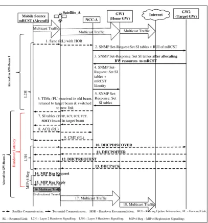
A GWH is when a BH takes place between two beams associated with different gateways. GWH always entails BH. The GWH is coordinated by the NCC which has a database that includes all beams, gateways and satellites profiles. Figure 2.2 shows the step-by-step DVB-S/RCS signalling messages between all
entities involved in a gateway handover [17]. Most often, a GWH involves a layer three handover, especially if the GWs are connected to the Internet or terrestrial networks. In such a scenario, a GWH will entail a layer 3 (IP Layer) handover since the IP address of the mobile satellite terminal will have to change.
Figure 2.2 Gateway handover signalling sequence
2.3.3 Satellite handover
A satellite handover (SH) takes place when a RCST moves from one beam into another one which belongs to a different satellite. SH always entails a BH and GWH. SH is coordinated by the NCC if the satellites belong to the same interactive network [21] and by the NMC if the satellites belong to different interactive networks of the same satellite operator. Since SH entails GWH, it means that SH requires handover at the IP layer.
1. Check positioning/link quality information, trigger HO recommendation (SYNC - RL)
2. SNMP Set-Request: Set SI tables + Routing Update Information (RUI) of mobile RCST mRCST to NCC
NCC to Target GW
3. SNMP Set-Response: Set SI tables, after allocating BW resources to RCST & joining M groups indicated in RUI
Target GW to NCC
6. TIMu ( HO cmd, new TDM, SF_ID, Group_ID, Logon_ID, PIDs, SYNC received in old beam for new beam, retune to target beam & switched to new link
5. SNMP Set-Response: Set SI tables 4. SNMP Set-Request: Set SI tables including RCST Identity
NCC to source GW
Source GW to NCC
NCC to mRCST
7. SI tables (TBTP, SCT, FCT, TCT, MMT) issued in target beam
8. ACQ (RL) - indicating mRCST re-synchronisation 9. CMT (FL) - in response to ACQ NCC to mRCST mRCST to NCC NCC to mRCST START END
Old link disconnected & New link established
2.4 Summary
In this chapter, an overview of the satellite network architecture (from the point of view of a DVB-RCS) is given. The key communication entities in satellite networks have been given and defined. This chapter also introduces the mobile scenarios envisaged in satellite networks. These are broadly classified into Line-Of-Sight (LOS) and Non-Line-Of-Sight (NLOS) scenarios. The three common types of handovers in satellite networks have been stated and explained.
After studying the satellite network architecture in this chapter, the next chapter examines the current IP mobile multicast support schemes in terrestrial networks in order to assess their suitability for adaptation in a multi-beam satellite network.
3 IP MOBILE MULTICAST SUPPORT SCHEMES AND
ADAPTATION TO THE SATELLITE ENVIRONMENT
This chapter explores the mobile multicast receiver/source issues and thecurrent proposed solutions to these problems in terrestrial networks. It also compares the current IP mobile multicast solutions with the view of establishing which ones could be suitable for adaptation in a multi-beam satellite network. Based on some defined parameters relevant to handover scenarios in a multi-beam satellite network, some of the terrestrial IP mobile multicast support schemes are considered to be good candidate schemes for adaptation in a satellite environment.
3.1 IP mobile multicast problems
In terrestrial networks, mobile multicast receivers/sources face similar problems like the ones explained in Section 1.4, due to changes in their IP addresses as they undergo layer 3 handover from one IP network to another.
3.1.1 Mobile receiver problems
The problems faced by mobile multicast receivers include:
• Multicast latency: - Due to handover procedures from one network to
another (e.g., link-switching delay, mobile IP protocol operations), membership protocol implementation, multicast tree reconstruction and increased propagation delays to new locations, mobile receivers experience extra delays in receiving multicast data. This could pose serious problems especially for time delay sensitive applications (e.g., voice, video conferencing, etc.).
• Packet loss: - This occurs mostly during handover period when the mobile
receiver is switching from one network point of attachment to another. During this period, the mobile receiver is unreachable i.e., cannot receive or send traffic and so the multicast traffic sent during this time frame is lost. • Packets out of order: - Due to delays and handover procedures, a mobile
node (MN) may receive some packets out of order.
• Packet duplication: - This occurs when a MN is receiving multicast packets
from different routers or base station as a consequence of its movement from one subnet to another.
• Leave latency: - A MN may not have enough time to unsubscribe to the
multicast groups it was previously subscribed to before losing connection to the previous network. This is particularly important if the MN was the last member of a multicast group in the subnet as multicast data will still continue to be forwarded to the subnet despite the fact that no member of the group is still left in the subnet.
3.1.2 Mobile source problems
Whereas the problem of a mobile receiver has a local and single impact on the receiver only, that of a mobile source (MS) is more important as it could affect the entire multicast group. During a handover procedure, the MS cannot send traffic when switching links from one IP network to another. For an ongoing multicast session, this could result in long multicast latency to the entire multicast group causing serious problems especially to real-time applications. The problems of mobile multicast sources are very serious particularly in SSM, where a receiver subscribes to a multicast channel (S, G) i.e., to receive traffic from a specified source identified by its IP address S. The mobile multicast sources problems in terrestrial networks are similar to the ones for satellite
networks described in Section 1.4. Due to these problems, the multicast traffic from the MS might not reach the group members.
3.2 Current solutions to IP mobile multicast problems
Many IP mobile multicast support schemes have been proposed to solve the problems of mobile multicast receivers/sources in terrestrial networks. In [25], a brief description of most of the proposed IP mobile multicast support techniques for terrestrial networks available today in open literature has been given. The IP mobile multicast support schemes proposed so far can be classified into four main categories; Home subscription (HS)-based approach, Remote subscription (RS)-based approach, Hybrid-based approach and Unicast/ Explicit (Xcast)-based approach [25].
In this section, the IP mobile multicast support schemes in each category will be compared to see which ones could be suitable for adaptation in supporting mobile multicast receivers/sources within a multi-beam satellite network. For any of these terrestrial schemes to be adapted for a satellite environment, they need to at least possess the following characteristics: short multicast disruption time; less overall signalling traffic and less signalling traffic over the wireless domain during handover; simple with explicit procedures/steps for supporting mobility (i.e., less complexity and no ambiguity); clear indication of how the newly defined multicast protocols (architectural entities) interoperate with the existing multicast protocols; etc. The following parameters in any given IP mobile multicast support scheme can give an indication of some of these characteristics:
• Number of mobility entities: The number of network entities required to
another can give an indication of the amount of signalling traffic, handover latency (disruption time) and level of complexity that could be encountered during a handover process. A higher number of mobility entities would suggest a larger amount of signalling traffic and a longer handover latency compared to one with a small number of mobility entities as these entities will have to communicate with each other during a handover process. Also, a mobile multicast support scheme with a higher number of mobility entities would suggest a more complex system compared to one with a small number of mobility entities. Coordination and integration of a larger number of mobility entities into a satellite system to support IP multicast mobility during handover will present a more challenging task compared to dealing with a mobility scheme with fewer number of mobility entities. So, it is imperative that the number of mobility entities involved in any handover process should be as few as possible in any scheme for it to be considered a good candidate for adaptation in a satellite environment.
• Level of involvement of the MN in the handover process. If the mobile
receiver has to make several contacts (too involved) with mobility entities during a handover process, this may suggest that the amount of signalling traffic over wireless domain at handover is high. Fewer contacts will therefore mean low amount of signalling traffic over wireless domain at handover. In a satellite network, a lot of signalling messages is not good as they consume scarce and expensive satellite bandwidth resources. This implies that any terrestrial scheme with high level of signalling messages in the wireless domain will not be suitable for the satellite environment as these signalling message plus the standard handover/control messages in satellite
![Figure 3.11 Base solution call flow for multicast communication during MS1 handover in PMIPv6 domain [64]](https://thumb-us.123doks.com/thumbv2/123dok_us/10126961.2913436/72.892.190.790.319.685/figure-base-solution-multicast-communication-handover-pmipv-domain.webp)