Slovak University of Technology Bratislava
Faculty of Informatics and Information Technologies
FIIT-13428-5796
Kamil Burda
PORT CONTROL PROTOCOL IN SOFTWARE DEFINED
NETWORKS
Diploma Thesis
Degree Course: Computer and Communication Systems and Networks Field of study: 9.2.4 Computer Engineering
Institute: Institute of Computer Systems and Networks, FIIT STU Bratislava Supervisor: Ing. Martin Nagy
Slovak University of Technology Bratislava
FACULTY OF INFORMATICS AND INFORMATION TECHNOLOGIES
Annotation
Degree Course: Computer and Communication Systems and Networks Author: Kamil Burda
Diploma Thesis: Port Control Protocol in Software Defined Networks Supervisor: Ing. Martin Nagy
2015, May
User applications, such as instant messaging or VoIP, may have problems traversing the network through middleboxes (NAT gateways, firewalls). Several mitigation techniques exist, including a relatively new protocol called Port Control Protocol (PCP). PCP allows user applications to receive IP address and port mapping directly from the middleboxes. Additionally, PCP allows user applications to optimize the number of keepalive messages sent to the network in order to maintain the connection, reducing the network load and prolonging battery life in mobile devices. Software defined networking (SDN) is a new paradigm in computer networks that allows the network behavior to be programmed. SDN networks increase flexibility and vendor compatibility by providing a standard communication interface for the network elements. The goal of the diploma thesis is to implement PCP over an SDN network (using the OpenFlow protocol) and to measure the reduction of keepalive traffic with PCP enabled in the implemented network, focusing on mobile networks, where the impact of the reduction of the signaling traffic may be considerable.
Slovenská technická univerzita v Bratislave
FAKULTA INFORMATIKY A INFORMAČNÝCH TECHNOLÓGIÍ
Anotácia
Študijný program: Počítačové a komunikačné systémy a siete Autor: Kamil Burda
Diplomová práca: Protokol PCP v softvérovo definovaných sieťach Vedúci diplomovej práce: Ing. Martin Nagy
máj 2015
Používateľské aplikácie, ako napr. rýchle správy (instant messaging) alebo VoIP, môžu mať problémy s komunikáciou v sieti cez sieťové zariadenia ako napr. brány NAT alebo bezpečnostné brány. Na zmiernenie problémov sa môžu použiť existujúce techniky, resp. protokoly, vrátane relatívne nového protokolu Port Control Protocol (PCP). Protokol PCP umožňuje používateľským aplikáciám získať informácie o mapovaní IP adries a portov priamo z uvedených sieťových zariadení. PCP navyše umožňuje optimalizovať vysielané množstvo tzv. správ keepalive (správy na udržiavanie spojenia), čím sa znižuje záťaž siete a predlžuje sa životnosť batérie na mobilných zariadeniach. Softvérovo definované siete (SDN), ako nový prístup budovania a riadenia sietí, umožňujú naprogramovať správanie sa siete. Siete SDN zabezpečujú vyššiu flexibilitu a kompatibilitu medzi zariadeniami od rôznych výrobcov vďaka štandardnému komunikačnému rozhraniu medzi týmito zariadeniami. Cieľom diplomovej práce je implementovať protokol PCP v sieťach SDN (s použitím protokolu OpenFlow) a určiť redukciu množstva správ keepalive s protokolom PCP v implementovanej sieti, pričom dôraz je kladený na mobilné siete, kde má redukcia signalizačnej sieťovej premávky značný vplyv.
Acknowledgments
I would like to thank my supervisor, Martin Nagy, for consultation regarding the diploma thesis. I would also like to thank my family for providing moral support.
Contents
Introduction...1 1. Middleboxes...2 1.1. NAT Gateway...2 2. User Applications...4 2.1. Keepalives...4 2.1.1. TCP Keepalives...42.1.2. Keepalives and Middleboxes...5
2.2. Middlebox Traversal Methods...5
2.2.1. STUN, TURN, ICE...5
2.2.2. Middlebox Signaling Protocols...5
2.2.3. UPnP IGD...6
2.2.4. Application Layer Gateway...6
3. Port Control Protocol...7
3.1. PCP Messages...8
3.1.1. PCP Request...8
3.1.2. PCP Response...9
3.1.3. MAP Opcode...10
3.1.4. PEER Opcode...11
3.1.5. PCP Server Recovery with ANNOUNCE Opcode...12
3.1.6. Options...12
3.2. PCP Request Processing by PCP Server...13
3.2.1. Learning, Modifying and Maintaining Mapping Lifetime...16
3.3. PCP Server Discovery...17
3.4. PCP Client Implementation...17
3.5. Available PCP Software...18
3.5.1. PCP Testing Tool...18
3.5.2. PCP Client Library...18
3.6. Comparison of PCP and Middlebox Traversal Methods...19
4. Mobile Networks...20
4.1. 3G Networks...20
4.2. Radio Resource Control...21
4.2.1. RRC States...22
4.2.2. RRC Inactivity Timers...23
4.2.3. RRC State Transitions with Keepalives...24
4.3. Conclusions...24
5. Software Defined Networking...26
5.1. OpenFlow...27
5.1.1. OpenFlow Switch Overview...27
5.1.3. Flow Entries...28
5.1.4. Instructions...29
5.1.5. Ports...29
5.2. SDN Software...30
5.2.1. Forwarders...30
5.2.2. OpenFlow Controller Software...30
6. Analysis Summary...32
7. Specification...34
7.1. Goals...34
7.2. Requirements...34
7.2.1. Port Control Protocol...35
8. Design...36
8.1. Architecture...36
8.1.1. Components...37
8.1.2. Network Application Components...38
8.2. PCP Client Mapping Request – Processing...39
8.3. Edge Forwarder...39
8.4. NAT Forwarder...40
9. Implementation...42
9.1. Implementation Environment...42
9.2. Implementation Description...43
9.2.1. ARP Message Processing...44
9.2.2. NAT Table...45
9.2.3. Managing Mapping Lifetime...46
9.3. Verification...46
10. Evaluation...47
10.1. Battery Life Extension...48
10.1.1. Battery Power Consumption Figures...48
10.1.2. Formulas...48
10.1.3. Results...50
10.2. Signaling Traffic Reduction...53
10.2.1. Network Traffic in WCDMA Networks...53
10.2.2. Formulas...53
10.2.3. Results...53
10.3. Conclusions...55
10.3.1. Determining PCP Mapping Lifetime...56
Summary...57
Conclusion...58
References...59
A. Attached DVD Contents...63
B. Installation...64
C. Using the Software...66
D. Plan of Work...71 Resumé...
Abbreviations
ALG Application layer gateway, Application-level gateway API Application programming interface
ARP Address Resolution Protocol CGN Carrier-grade NAT
DHCP Dynamic Host Configuration Protocol EDGE Enhanced Data rates for GSM Evolution EIR Equipment Identity Register
GGSN Gateway GPRS Support Node GMSC Gateway Mobile Switching Center GPRS General packet radio service
GSM Global System for Mobile Communications HLR Home Location Register
HSPA High Speed Packet Access
IANA Internet Assigned Numbers Authority ICE Interactive Connectivity Establishment IETF Internet Engineering Task Force IP Internet Protocol
IPsec Internet Protocol Security LTE Long-Term Evolution MAC Media Access Control MSC Mobile Switching Center
NAPT Network address and port translation NAT Network address translation
NAT-PMP NAT Port Mapping Protocol OS Operating system
PCP Port Control Protocol PDN Packet data network
PSTN Public Switched Telephone Network RFC Request for Comments
RNC Radio Network Controller RRC Radio Resource Control SDN Software defined networking
SGSN Serving GPRS Support Node STUN Session Traversal Utilities for NAT TURN Traversal Using Relays around NAT
UMTS Universal Mobile Telecommunications System UPnP Universal Plug and Play
UPnP IGD Universal Plug and Play Internet Gateway Device VLR Visitor Location Register
VoIP Voice over IP Protocol
WCDMA Wideband Code Division Multiple Access XML Extensible Markup Language
Figures
Figure 1.1: Example of address translation by a NAT gateway...2
Figure 3.1: Usage of PCP in networks...8
Figure 3.2: PCP request message format...9
Figure 3.3: PCP response message format...10
Figure 3.4: Message format for MAP opcode for PCP request...11
Figure 3.5: Message format for PEER opcode for PCP request...12
Figure 3.6: Generic header for PCP options...13
Figure 3.7: Basic processing of a PCP request by the PCP server...14
Figure 3.8: Building a PCP response from the corresponding PCP request by the PCP server...15
Figure 3.9: Processing of PCP MAP and PEER requests...16
Figure 4.1: Architecture of 3G networks...21
Figure 4.2: Radio Resource Control (RRC) states...23
Figure 4.3: Possible RRC state transitions when sending a single keepalive...24
Figure 5.1: SDN architecture overview...26
Figure 5.2: Overview of an OpenFlow switch (forwarder)...27
Figure 5.3: Flow entry structure in an OpenFlow switch...28
Figure 6.1: PCP Deployment in Traditional Networks...32
Figure 8.1: Architecture of the network...36
Figure 8.2: NAT table entry fields...38
Figure 8.3: Network application components...38
Figure 8.4: PCP request processing by the network application...39
Figure 8.5: Edge forwarder flow entries...40
Figure 8.6: NAT forwarder flow tables and entries...41
Figure 9.1: Test topology for verification...42
Figure 9.2: Forwarder implementation overview...43
Figure 9.3: Example of a MAC overwriting flow entry installation with proxy ARP approach...45
Figure 10.1: Amount of battery power saved based on keepalive intervals relative to reference values and cost of 0.15 mAh per keepalive...51
Figure 10.2: Amount of battery power saved based on keepalive intervals relative to reference values and cost of 0.6 mAh per keepalive...51
Figure 10.3: Amount of battery lifetime saved based on keepalive intervals relative to reference values and cost of 0.15 mAh per keepalive...52
Figure 10.4: Amount of battery lifetime saved based on keepalive intervals relative to reference values and cost of 0.6 mAh per keepalive...52
Figure 10.5: Number of signaling messages reduced based on keepalive intervals and reference values (40 observed messages)...54
Figure 10.6: Number of signaling messages reduced based on keepalive intervals and reference values (50 observed messages)...54 Figure 10.7: Number of signaling messages reduced based on keepalive intervals and reference
values (20 unobserved messages)...55
Figure 1: PCP Request processed by the PCP server in the controller...67
Figure 2: Packet trace from host 1...68
Tables
Table 4.1: Average current (power consumption) of a mobile device in RRC states [30] [5] [29]....23 Table 10.1: Measured battery power consumption of keepalives in 3G WCDMA networks [5]...48 Table 10.2: Amount of battery power consumption saved of a mobile device connected a WCDMA network given battery capacity and reference values...50 Table 10.3: Reduction of the number of signaling messages given the number of messages per keepalive and reference values...55 Table 1: Plan of work for the diploma thesis...71 Table 2: Plan of work – assessment...71
Introduction
User applications running on hosts, such as instant messaging (IM) or VoIP, may have problems traversing the network through the so called middleboxes placed in computer networks, especially NAT gateways. In order to mitigate the incompatibility of user applications with NAT, several approaches exist, such as Session Traversal Utilities for NAT (STUN).
With the middleboxes in the network, the user applications have to keep the connections alive to avoid the middleboxes closing the connections prematurely. This is accomplished by sending keepalive messages from the user applications to the destination host in regular intervals. Given the fact that the user applications do not know the keepalive timers set on the middleboxes, they tend to send the keepalives in very short intervals, increasing the network load.
In mobile networks, each message sent over the network causes a substantial number of signaling messages to be generated and sent over the network. With a large number of mobile devices connected to the network and running one or more applications, this introduces increased network load in the network and delay in communication. From the perspective of a mobile device, sending an excessive amount of keepalives drains its battery life faster.
Port Control Protocol (PCP) is a relatively new protocol that allows user applications to receive mapping information directly from the middleboxes, including external IP address and port in case of NAT gateways, and the mapping timer. The applications can consequently optimize their keepalive timers using this information.
Software defined networking (SDN) is a new paradigm in computer networks that allows the network behavior to be programmed in a simpler manner. SDN networks increase flexibility and improve vendor compatibility by providing a standard communication interface between the network elements, such as OpenFlow.
The goal of the diploma thesis is to implement PCP over SDN networks and to measure the keepalive traffic reduction with PCP enabled in the networks, focusing on mobile networks, where the impact may be considerable.
Chapters 1 and 2 of the document describe middleboxes and their role in the computer networks, user applications and their traversal issues over the middleboxes and related methods that provide solutions to the traversal issues. Chapter 3 focuses on one of the traversal methods – the most essential part of this thesis – the PCP protocol. Chapter 4 gives a brief overview of mobile networks and further focuses on 3G networks using the Wideband Code Division Multiple Access (WCDMA) access technology. Chapter 5, the last part of the analysis, discusses the concept of SDN. Chapter 6 summarizes the analysis and gives an overview of the current state of the networks and issues to be resolved.
Chapter 7 specifies the goals of the diploma thesis and the requirements for the solution. Chapter 8 describes the design of the solution. Chapter 9 describes the most important aspects of the implementation of the solution and describes how to verify the solution. Chapter 10 evaluates the reduction of battery power consumption of mobile devices and the reduction of signaling traffic in WCDMA networks with PCP deployed in the network.
1. Middleboxes
Middlebox is a term that refers to “any intermediary device performing functions other than the normal, standard functions of an IP router on the datagram path between a source host and destination host” [1].
Source [1] identifies several types of middleboxes, mainly: • NAT gateways,
• firewalls,
• application-level gateways (ALGs).
Generally speaking, IP routing and the corresponding routers are transparent to end hosts. This transparency is broken by introducing middleboxes in the network, as the middleboxes alter the packet forwarding. Thus, end hosts must now cope with middleboxes as well when establishing communication [1].
While ALGs can be classified as middleboxes, they enable end hosts to properly traverse other middleboxes – NAT gateways and firewalls. Hence, ALGs as one method to traverse other middleboxes are described in section 2.2.4.
1.1. NAT Gateway
A NAT gateway is a network device that performs network address translation [2]. A carrier-grade NAT (CGN) is a NAT gateway located in service-provider networks [4]. Figure 1.1 illustrates an example of a packet being subject to translation by a NAT gateway in the network. NAT allows hosts from private networks (such as 192.168.0.0/16) to communicate with hosts on the Internet – on the public network with publicly routable IP addresses.
More importantly, NAT can conserve IPv4 address space by translating multiple internal (private) IP addresses to one external (public) IP address with different transport protocol ports. This type of NAT is called Network Address and Port Translation (NAPT). When overwriting packet fields, NAT gateways must recompute the checksum of each relevant header (IP, transport protocol, Ethernet frame).
In this document, unless otherwise specified, “NAT” refers to the general network address translation process to simplify discussion. It does not imply NAPT or address translation exclusive to IP.
The translation between an internal IP address, protocol and port and an external IP address, protocol and port can be referred to as a mapping. NAT gateway stores mappings for each connection. Mappings can be created statically (manually configured by the network administrator) or dynamically (created one a packet traverses through the NAT gateway). In case of a dynamic mapping, the NAT gateway allocates an external IP and an external port from the pool of defined external IP addresses and ports.
An idle timer may be associated for each mapping. If no packet traverses through the NAT gateway for this connection, the mapping is removed by the gateway. Employing a timer for a mapping may have several reasons.
NAT gateways do not participate in the end-to-end connection between the communicating hosts. Hence, NAT gateways generally cannot determine when the connection is terminated. For TCP connections, NAT gateways may track segments with FIN or RST flags, in which case the gateways may remove the mapping immediately upon receiving such segments. Other transport protocols, such as UDP, do not indicate when the connection terminates. Additionally, the NAT gateways cannot detect one or both communicating hosts suddenly terminating the connection (e.g. by crashing) [2]. Another reason to add timers to mappings is to conserve memory on NAT gateways or keep the NAT pool for dynamic mappings from being depleted too quickly.
According to several vendor devices specified in source [5], the default timer values for TCP range from 30 to 150 minutes and for UDP from 60 to 300 seconds.
2. User Applications
Certain user applications need to communicate with hosts behind NAT or similar middleboxes. Such applications have problems traversing the middleboxes because of unexpected IP address and port rewrite on the route to the destination. These applications include VoIP, social networks, instant messaging or online gaming, and are sometimes referred to as always-on applications.
The data transmitted in these applications are intermittent. That is, no data may be sent for a certain period of time. This poses another problem for the applications – middleboxes shut down idle connections and the applications would have to establish the network connections again.
To avoid the network connections being shut down by middleboxes, user applications send keepalive messages [6] to the destination. The keepalives usually contain little to no payload to conserve network load.
2.1. Keepalives
Keepalives are messages sent by end-user applications to check for broken connections or to prevent disconnection due to inactivity [7]. Without keepalives, the connection can be broken if there are middleboxes on the path between the end hosts, such as NAT gateways. Middleboxes maintain mapping information for each connection and assign a timeout for the mapping. If no messages are sent within the connection for the time specified by the timeout, the middlebox removes the mapping and the connection is broken.
The format of keepalives and their usage depends on the communication protocol used. Keepalives tend to be short in length to preserve the network bandwidth [7].
2.1.1. TCP Keepalives
Once established, a TCP connection lasts until it is closed explicitly by either host. There is no connection timeout associated with the established TCP connection if no messages are sent for a long time [8]. This implies that if, for example, the remote host crashes, the local host has no way of learning that the remote host no longer maintains the connection. Periodically sending TCP keepalives can detect such broken connections [6].
A host desiring to maintain a TCP connection sends an empty ACK segment to the destination host. The destination host replies with another ACK segment. The size of the segment payload can be zero (i.e. no data need to be included in the segments) [7].
The implementation of TCP keepalives is optional. If sending TCP keepalives is implemented, it must be turned off by default [6]. Applications may enable or disable keepalives and may adjust the keepalive time. By default, the keepalive time must be set to at least two hours [6].
Among the more popular platforms, Windows1, Linux2 and OS X3, support TCP keepalives and also support setting the keepalive time. Popular platforms for mobile devices, such as Windows Phone, Android, iOS, also support TCP keepalives and keepalive time, given that these platforms 1 https://msdn.microsoft.com/en-us/library/dd877220%28VS.85%29.aspx
2 http://tldp.org/HOWTO/TCP-Keepalive-HOWTO/usingkeepalive.html
are based on Windows, Linux and OS X, respectively.
2.1.2. Keepalives and Middleboxes
For communication passing through NAT gateways, IETF requires setting the mapping lifetime (timeout) for UDP to at least 120 seconds (with 300 seconds recommended) [9] and for TCP to at least 124 minutes [10]. For IPSec ESP connections, the keepalive interval is locally configurable, with the default value of 20 seconds [11].
2.2. Middlebox Traversal Methods
2.2.1. STUN, TURN, ICE
Session Traversal Utilities for NAT (STUN) [12] is a protocol that helps application protocols cope with NAT traversal. STUN uses a client-server model for message exchange. STUN can also be used as a keepalive mechanism.
STUN can be used by hosts – STUN clients – to determine their external IP address and port allocated by a NAT gateway from a STUN server. The STUN server usually resides on the public Internet.
The operation of STUN is simple. The STUN client sends a request to the STUN server on the public Internet. From the request, STUN server sees the source IP address and port as the external IP address and port of the STUN client, since the NAT gateway translated the source IP address and port of the request. The STUN server encapsulates the external IP address and port to the payload of a response message that is then sent back to the STUN client. The host thus receives its external mapping information.
The advantage of STUN is that it does not require modifications of NAT gateways. The disadvantage of STUN is that is does not work properly with symmetric NAT4.
Traversal Using Relays around NAT (TURN) [13] defines an intermediate node – a relay (or a TURN server). End hosts use the relay to forward data traffic through (such as voice). In case of TURN, it is possible for one host to communicate with multiple other hosts with the same external IP address and port. While TURN can support symmetric NAT, the relays are subject to heavy network load.
Interactive Connectivity Establishment (ICE) [14] is a technique that combines STUN and TURN and chooses the most effective way of communication between hosts behind a NAT5.
2.2.2. Middlebox Signaling Protocols
This subsection gives a brief overview of protocols that, unlike the previously mentioned protocols, communicate with middleboxes directly.
NAT Port Mapping Protocol (NAT-PMP) [3] is the predecessor to the Port Control Protocol (described in chapter 3). NAT-PMP allows the host to receive its external IP address and external port. NAT-PMP works only on NAT gateways located one hop away from the host.
4 More information at: http://think-like-a-computer.com/2011/09/19/symmetric-nat/ 5 More information at: http://www.pjsip.org/pjnath/docs/html/group__PJNATH__ICE.htm
Two more middlebox signaling protocols include Middlebox Communication Architecture and Framework (MIDCOM) [15] and NEC's Simple Middlebox Configuration Protocol (SIMCO) [16]. These protocols appear to be outdated as they were not widely deployed in networks despite being in existence many years.
2.2.3. UPnP IGD
The Internet Gateway Device (IGD) is a device on the edge of a LAN and a WAN network, allowing end users to connect to the Internet. IGD as a UPnP-based protocol allows users to control and configure multimedia devices connected to the network, including the configuration of DHCP, DNS and also the network address translation on the IGD device [17].
2.2.4. Application Layer Gateway
An application layer gateway6 is a software component that manages specific protocols notorious for having problems with NAT traversal, such as Session Initiation Protocol (SIP) or File Transfer Protocol (FTP). ALG can examine the payload of packets and determine whether NAT needs to be performed. The use of ALGs has been discouraged [18].
6 More information at: https://www.juniper.net/techpubs/software/junos-es/junos-es93/junos-es-swconfig-security/application-layer-gateways-algs.html
3. Port Control Protocol
Port Control Protocol (PCP) [18] [19] [20] allows network hosts to communicate directly with middleboxes (NAT gateways or firewalls). With PCP, the host can receive or explicitly request a mapping from an internal IP address, protocol and port to an external address, protocol and port. This way, the host can traverse NAT gateways properly and communicate with other hosts behind NAT.
PCP does not provide a mechanism to inform the remote host about the host's external mapping. This responsibility is left to the user application and is usually handled by a rendezvous (proxy) server, accessible in the public network by both communicating hosts.
The mapping assigned by the middlebox to the host also contains mapping lifetime – the timer associated with the mapping. PCP also retrieves the lifetime value from the mapping. Given the mapping lifetime, the application running on the host can optimize the interval of sending keepalives over the network. Reduced keepalive traffic can extend the battery life of mobile devices and reduce network traffic overhead [18] [21].
PCP originated as an alternative to application layer gateways (ALGs) [18], existing protocols for NAT traversal such as STUN7, and existing protocols facilitating communication with middleboxes, such as UPnP IGD [3]. PCP as a relatively new protocol was standardized by IETF in April 2013 as RFC 6887 [18] and is the successor to NAT Port Mapping Protocol (NAT-PMP) [3].
PCP can be deployed in several scenarios [18]:
• home networks with NAT gateways (e.g. integrated in routers), • carrier-grade NAT,
• simple firewalls.
PCP supports both IPv4 and IPv6 address mapping and transport protocols with 16-bit port numbers. PCP also supports protocols that do not use port numbers (such as IPsec ESP or ICMP) for firewalls, but not NAT gateways [18].
As defined in RFC 6887, PCP can be operational only in single-homed networks. If a network is single-homed, only one route exists to the Internet. The recently released RFC 7488 provides support for multi-homed networks [22].
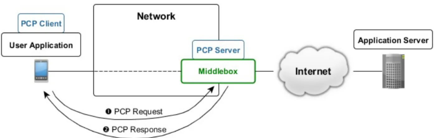
Figure 3.1 shows the typical deployment and usage of PCP in networks. The host runs a user application that attempts to connect to the application server. The application retrieves mapping information from the middlebox in order to establish the connection or optimize the interval of sending keepalive messages.
The application invokes the PCP client to request mapping information from the middlebox. The middlebox runs the PCP server, which processes the request of the PCP client and sends back mapping information.
3.1. PCP Messages
PCP defines two message types: PCP request and PCP response.
PCP messages are sent over UDP and are not acknowledged. PCP request uses destination UDP port 5351 and PCP response uses source UDP port 5351.
The PCP request is used by the host to request mapping information from the PCP server. The PCP response is used by the PCP server to inform the PCP client of the state of the mapping, usually informing the PCP client that the mapping information has been assigned to the PCP client.
PCP can be considered a request/response protocol. This point of view may not be accurate – unlike other request/response protocols, a PCP request does not necessarily have to be followed by a PCP response. If a PCP request sent by the PCP client was lost on the path to the PCP server, the PCP client may retransmit the same message. The PCP client can also use the same PCP request to renew the mapping information. The PCP server usually generates PCP responses to PCP requests sent by PCP clients. The PCP server may also send a PCP response to inform the PCP client about the new state of the mapping, e.g. because of middlebox reconfiguration or failure. Given the message exchange model, RFC 6887 refers to PCP as a hint/notification protocol [18].
PCP messages contain fields with IP addresses, such as the external IP address of the host assigned by the PCP server. IP addresses in PCP messages are always formatted as IPv6 addresses. IPv4 addresses are represented as IPv4-mapped IPv6 addresses:
::ffff:<IPv4 address>
3.1.1. PCP Request
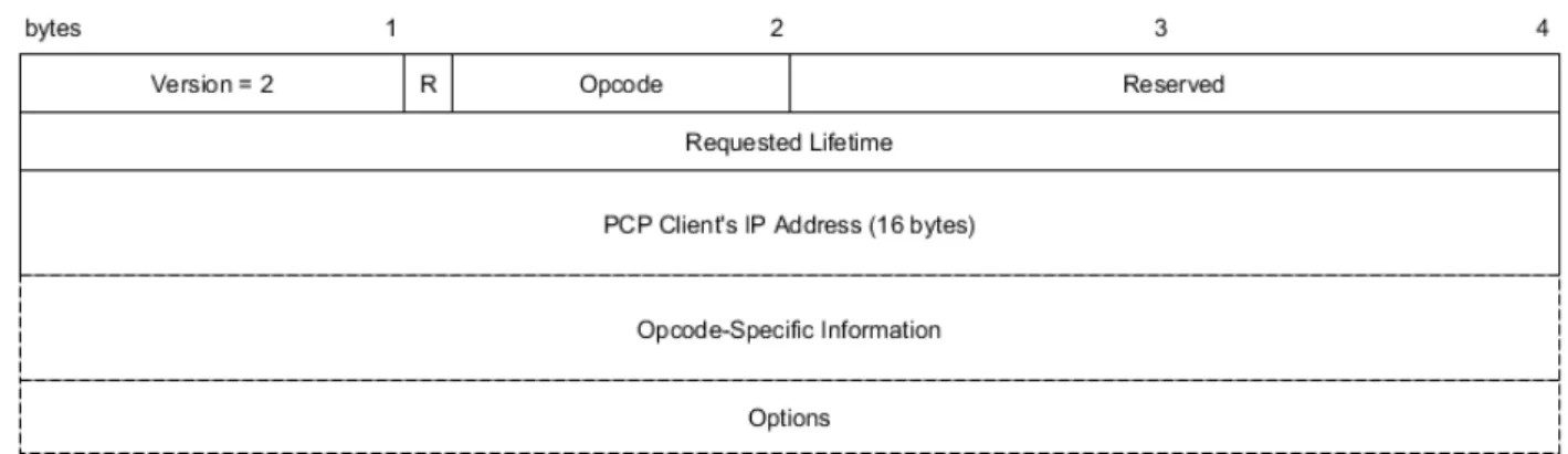
Figure 3.2 shows the common header format for PCP requests. Figure 3.1: Usage of PCP in networks
The PCP request contains the following fields:
• Version – for PCP, this value is always set to 2. This field can be used to determine the supported version of PCP on the PCP server, should newer versions of PCP are defined. • R – 1-bit field – 0 indicates PCP request.
• Opcode – 7-bit operation code for the PCP request. In RFC 6887, the following opcodes are defined: MAP (1), PEER (2) and ANNOUNCE (0). Opcodes are discussed in sections 3.1.3, 3.1.4 and 3.1.5, respectively.
• Reserved – zero-padded bits, ignored by PCP server.
• Requested Lifetime – mapping lifetime requested by PCP client. If the field is set to zero, the PCP server deletes the mapping.
• PCP Client's IP Address – IP address of the PCP client in IPv6 format. This field is used by the PCP server to determine additional middleboxes along the path from the PCP client that do not run the PCP server.
• Opcode-Specific Information – additional fields defined by the corresponding opcode. • Options – a set of optional fields in the type-length-value format. Options can be ignored by
the PCP server. A brief overview of options is given in section 3.1.6.
3.1.2. PCP Response
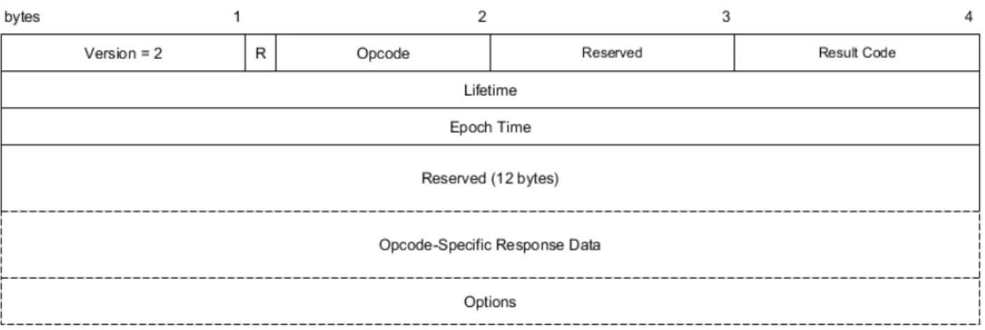
The format of a PCP response message is shown in Figure 3.3. Figure 3.2: PCP request message format
The PCP response contains the following fields: • Version – set to 2 by the PCP server.
• R – 1-bit field set to 1, indicating PCP response. • Opcode – copied from the PCP request.
• Reserved – zero-padded bits.
• Result Code – value indicating a successfully processed PCP request (0, SUCCESS) or processing failure (values 1-14, depending on the type of failure). The meaning of each result code is described in RFC 6887 [18].
• Lifetime – mapping lifetime assigned by the PCP server to the PCP client.
• Epoch Time – time in seconds since the PCP server started operation. This is used by the PCP client to determine whether the PCP server lost state (e.g. if the PCP server crashed and rebooted). If so, the PCP client recreates its mapping information as per RFC 6887 [18]. • Reserved (12 bytes) – if the PCP request was parsed successfully, Reserved contains zero
bits. Otherwise, the field contains the last 12 bytes (96 bits) of the PCP Client's IP Address field in the PCP request.
Opcode-specific information and options for PCP responses are covered in subsequent sections.
3.1.3. MAP Opcode
A PCP client uses a PCP MAP request in case a user application desires to host a server (for online gaming, a web server, etc.) and listen for incoming traffic from the public network. After the PCP client received mapping information, it is the responsibility of the application to announce its external (public) IP address, protocol and port to a rendezvous server, as mentioned in the introduction of this chapter, as PCP does not provide this function [18].
The format of the MAP opcode for a PCP request is shown in Figure 3.4. Figure 3.3: PCP response message format
The MAP opcode for PCP requests contains the following fields:
• Mapping Nonce – random value generated by the PCP client. The PCP client uses this value to validate PCP responses [18].
• Protocol – protocol above the IP header. The protocol numbers are identical to those defined by IANA8.
• Reserved – zero-padded bits.
• Internal Port – internal port that the user application wishes to use to establish a connection. • External Port – external port preferred by the user application. If the application does not
require a specific external port, 0 is assigned.
• External IP address – external IP address in IPv6 format preferred by the user application. If the application does not require a specific external IP address, all-zeros IPv6 address is assigned (i.e. “::”).
The PCP response containing the MAP opcode copies all fields from the corresponding MAP request except External Port and External IP address. The PCP server assigns the external IP address and port according to the mapping entry created by the underlying middlebox.
3.1.4. PEER Opcode
A PCP client uses a PCP PEER request if a user application wishes to establish an outbound connection to an application server (i.e. the application acts as a client) in the public network or in another local network behind NAT [18].
A PCP PEER request can also be used by the PCP client to query existing mapping, e.g. in case the middlebox created an implicit mapping without the application communicating with the PCP server first.
The format of the PCP PEER request is shown in Figure 3.5. The message format is content-wise almost identical to PCP MAP messages. PCP PEER messages define two additional fields:
• Remote Peer Port – port of the remote host the user application wishes to establish connection with.
8 http://www.iana.org/assignments/protocol-numbers/protocol-numbers.xhtml
• Remote Peer IP address – IP address in IPv6 format of the remote host the user application wishes to establish connection with.
3.1.5. PCP Server Recovery with ANNOUNCE Opcode
PCP offers a mechanism for recovering mappings if the PCP server lost its state (e.g. crashed and rebooted). This mechanism allows PCP clients to recover mappings within seconds. Otherwise, the PCP clients would not know that the state of the PCP server was reset, until they send the next keepalive, which may be a long time ahead depending on the keepalive interval. This would encourage applications to request shorter keepalive intervals, which would increase network load.
Once the PCP server reboots, it resets its epoch time to zero and sends PCP ANNOUNCE response to PCP clients to multicast address 224.0.0.1:5350 (or [ff02::1]:5350 in case of IPv6). A PCP client, having received the PCP response with invalid epoch time (set to zero), determines that the PCP server lost its state. The PCP client then sends a PCP request with the appropriate opcode (MAP or PEER) and include the external IP address and port assigned by the PCP server before losing its state, reminding the server of the mapping assigned.
The PCP ANNOUNCE request can be used by the PCP client to determine whether the PCP server is running or maintains its state (by checking the epoch time). PCP ANNOUNCE messages do not contain any opcode-specific fields [18].
3.1.6. Options
This section briefly introduces the available options for PCP messages. A generic format for options is shown in Figure 3.6. Option Code determines the option type, Option Length defines the length of the option header and Option Data contains option-specific data.
THIRD_PARTY
This option allows the PCP client to handle PCP requests on behalf of another host (specified by the internal IP address in the option data). It is recommended to not use this option due to security concerns. This option is valid for MAP and PEER opcodes [18].
PREFER_FAILURE
Without this option, if the PCP client requires a specific external IP address and port to be assigned and the PCP server cannot comply to the request, the PCP server assigns different external IP address and port. With this option, the PCP server will not create a mapping with explicit external IP address and port if it cannot create it and returns a PCP response indicating failure.
This option may be necessary in scenarios where the user application must explicitly specify an external IP address or port. It is expected that, with the potentially wider deployment of PCP in networks, this option will be deprecated in the future. This option is valid for MAP and PEER opcodes [18].
FILTER
This option allows the PCP client to filter incoming traffic with unwanted IP addresses and ports. To filter the traffic, the PCP client specifies the remote peer IP address and port which the application allows to receive traffic from. All other traffic is filtered by the middlebox. The FILTER option also allows specifying an entire subnet of remote hosts to be permitted (by using the Prefix Length field).
The FILTER option is useful for mobile devices that have to change their connection state solely for the purpose of rejecting unwanted traffic. Using the FILTER option prevents this and consequently saves battery life of mobile devices. Connection states and their impact on the battery life of mobile devices is further discussed in chapter 4.
In practice, the FILTER option can be used by applications hosting a server whose public IP address and port are known to other hosts on the Internet. One such case may be a game server that is published in a list of available game servers that the players (other client devices) can connect to. Filtering unwanted traffic or restricting the traffic to specific players can be desirable.
This option is valid for the MAP opcode only [18].
3.2. PCP Request Processing by PCP Server
This section contains an overview of how the PCP server processes a PCP request. Several details and edge cases were omitted to focus on the most important aspects of PCP message processing.
RFC 6887 contains detailed information about PCP message processing [18].
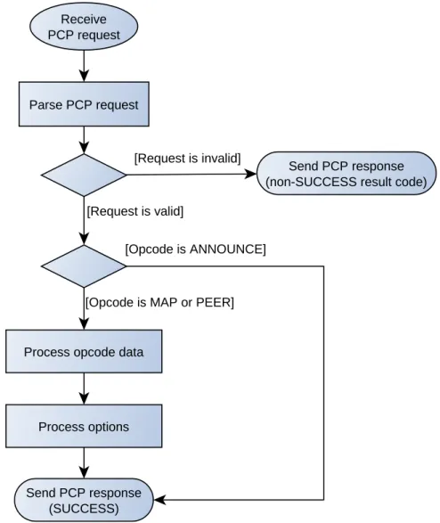
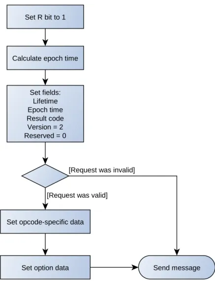
The basic processing steps are shown in Figure 3.7. A request may be invalid due to incorrect version or invalid length of the message. In that case, the PCP server sends a PCP response back to the PCP client with the result code corresponding to the type of failure. If a request is valid, the PCP server processes the opcode-specific data and options, if any. Finally, the PCP server builds a PCP response according to the flowchart in Figure 3.8 and sends it toward the PCP client. The processing of MAP and PEER opcode data is shown in Figure 3.9.
Figure 3.7: Basic processing of a PCP request by the PCP server
Parse PCP request Receive PCP request
Send PCP response (non-SUCCESS result code)
Process opcode data
Send PCP response (SUCCESS) Process options
[Request is invalid]
[Request is valid]
[Opcode is MAP or PEER] [Opcode is ANNOUNCE]
Figure 3.8: Building a PCP response from the corresponding PCP request by the PCP server
Set R bit to 1
Calculate epoch time
Set fields: Lifetime Epoch time Result code Version = 2 Reserved = 0 Send message Set opcode-specific data
Set option data
[Request was invalid]
Creating, updating or deleting a mapping entry is the responsibility of the underlying middlebox. The PCP server provides the middlebox with mapping information according to its configuration. If the middlebox created a new mapping, the PCP server receives the created mapping and sends it back to the PCP client.
If the external IP address is 0, the PCP server orders the middlebox to allocate an external IP address. The same applies to the external port.
If the PCP client explicitly specified an external IP address, the PCP server checks whether the middlebox can create a mapping with such IP address. If not, the PCP server then allocates a valid external IP address. If the PREFER_FAILURE option is specified, the PCP server will not allocate a different IP address and instead sends back a PCP response with CANNOT_PROVIDE_EXTERNAL result code [18].
3.2.1. Learning, Modifying and Maintaining Mapping Lifetime
If a user application established connection with a remote host without negotiating a mapping entry from the PCP server first, the PCP client can then send the PCP PEER request to learn the mapping lifetime and the application can thus optimize the keepalive interval.
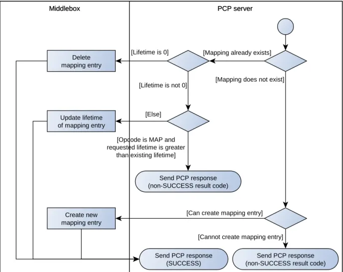
Figure 3.9: Processing of PCP MAP and PEER requests
Middlebox PCP server
Middlebox PCP server
Send PCP response (non-SUCCESS result code)
Create new mapping entry
Send PCP response (SUCCESS)
Send PCP response (non-SUCCESS result code) Delete
mapping entry
Update lifetime of mapping entry
[Lifetime is not 0]
[Opcode is MAP and requested lifetime is greater
than existing lifetime]
[Mapping already exists]
[Mapping does not exist]
[Cannot create mapping entry] [Can create mapping entry] [Lifetime is 0]
PCP-PEER-created mappings
Using the PCP PEER request, the PCP client can extend the mapping lifetime (i.e. maintain the mapping). The PCP PEER request cannot be used to reduce the mapping lifetime or delete the mapping [18]. To delete the mapping, the PCP client and the PCP server have to let the mapping entry on the middlebox expire on its own.
To maintain the mapping, the PCP client should send PCP PEER requests regularly to the PCP server. The interval of sending PCP requests is 1/2 to 5/8 of the lifetime (randomly chosen). Sending PCP PEER requests to maintain the mapping is not mandatory – if the PCP client does not send PCP PEER requests, the mapping behaves as a mapping implicitly created by the middlebox [18].
Assuming that implicitly created mappings on middleboxes that were once maintained by the PCP server use the same lifetime, it is sufficient for the PCP client to send keepalives to the remote host (without sending any PCP PEER requests to the PCP server).
PCP-MAP-created mappings
Mappings created by PCP MAP requests can only have their lifetime reduced or deleted.
To maintain a MAP-created mapping, the PCP client must send MAP requests to the PCP server in the same interval as PCP PEER requests mentioned above. Additionally, as per the requirements of the user application, the application may have to send keepalives to the remote host (e.g. to check for connectivity) [18].
3.3. PCP Server Discovery
PCP clients need to know the address of the PCP server in order to be able to request mapping information. The following alternatives are suggested in RFC 6887:
• PCP clients configure the PCP server address manually,
• PCP clients receive one ore more PCP server addresses via DHCP. RFC 7291 provides direct support for this approach [23].
• PCP clients assume that the PCP server IP address is the address of the host's default router (default gateway).
A related RFC draft suggests sending a PCP anycast address to discover PCP servers in the network [24].
3.4. PCP Client Implementation
RFC 6887 does not specify how the PCP client should be implemented – whether as an OS-level service or in each user application individually.
Implementing custom modifications of the PCP client outside the scope of the PCP RFC standard should be avoided since it is not expected that custom features could be widely deployed in PCP clients.
Implementing the PCP client as an OS-level service requires that operating systems support the PCP client service. For practical reasons, it is not expected that the current or older versions of
operating systems (desktop and mobile alike) will add support for the PCP client service. Each user application would still have to be PCP-aware in that it would have to interact with the PCP client service.
It is more practical to implement the PCP client per-application. The potential disadvantage is the fact that each application may have to determine the PCP server address individually. Using the DHCP approach mitigates this shortcoming, as it allows any application to determine the PCP server address.
3.5. Available PCP Software
This section gives a brief overview of chosen software that implements PCP.
3.5.1. PCP Testing Tool
PCP Testing Tool9 is a software tool consisting of two components – a web application and a PCP client.
The web application allows the user to specify a PCP message by filling in individual fields. Once the user specified the fields and confirmed to create the message, the web application generates a message containing XML-formatted fields of a PCP message to the PCP client. The IP address and port of the PCP client that listens to the requests from the web application can be configured. The web application requires Apache web server and PHP to run.
The PCP client is a PCP client implementation of PCP. If the PCP client receives a message from the web application, the PCP client constructs a PCP request from the message to the PCP server specified in the corresponding configuration file. The configuration file allows to specify IP addresses in IPv6 format – if an IPv4 address needs to be specified, it must be specified as an IPv4-mapped IPv6 address.
Given its web interface, this tool is user-friendly in the sense that it easily allows the user to build a PCP message. The disadvantage of this tool may be that it does not provide a command-line interface to build messages, which may be useful when automating the building of PCP messages (e.g. via shell scripts).
3.5.2. PCP Client Library
The PCP client library10 contains a library of functions implementing the PCP client that can be integrated in user applications, a lightweight command-line PCP client application and a module that allows to build packets using the scapy11 command-line packet builder.
With the application, the user can send a PCP request to a PCP server. An example usage of this appliction is shown below:
pcp -i <internal host IP address>:<internal port> -s <PCP server address> -l 3600
The -i option specifies the address of the internal host that is to be mapped to an external
9 Available at: http://sourceforge.net/projects/pcptestingsuits/ 10 Available at: https://github.com/libpcp/pcp
address, and an internal port to be mapped to an external port. While it may seem redundant to specify the internal IP address, the application will not work without it. This is also necessary to specify in case the host has multiple IP addresses (multiple interfaces). The -l option specifies the requested mapping lifetime in seconds.
The command above generates a PCP MAP request for TCP. To specify a PCP PEER request, the remote peer IP address and port have to be specified:
pcp -i <internal host IP address>:<internal port> -s <PCP server address> -l 3600 -p <remote peer IP address>:<remote peer port>
The -u option creates a mapping for UDP. An explicit IP address and port can be specified by the
-e option:
pcp -i <internal host IP address>:<internal port> -s <PCP server address> -l <lifetime> -e <external IP address>:<external port>
3.6. Comparison of PCP and Middlebox Traversal Methods
Compared to similar protocols or middlebox-traversal methods, PCP has the following advantages:• PCP can optimize keepalive traffic,
• PCP can resolve NAT traversal issues and eliminate the need to deploy ALGs [18], • PCP has a simple protocol design.
PCP imposes the following requirements on the network, which may be seen as disadvantages: • each user application must implement a PCP client,
• each middlebox that is supposed to be PCP-aware must run a PCP server.
While UPnP-IGD allows end users to configure mapping information, even programatically, PCP transmits fewer messages (therefore is more bandwidth-efficient) and does not need to be configured by users [3].
While the original PCP RFC [18] states that PCP can be used for simple firewalls, a relatively recent RFC draft has been published that adds support for new PCP message types that support advanced firewall functionality in managed networks, such as software defined networks (SDN) [25].
4. Mobile Networks
Mobile networks allow end users to connect to the Internet and communicate with each other in a wireless manner using mobile devices. Over the decades, several generations of mobile networks have been developed and deployed to cope with the increasing demand of users staying connected while moving.
The first generation of networks (developed in the 1980s) allowed users to establish phone calls. The data transmission in 1G networks was analog, unlike later generations, which used digital data transmission.
2G networks originated in the later 1980s, of which Global System for Mobile Communications (GSM) became the most popular and widespread 2G technology. Despite newer mobile network technologies, GSM is still widely used in the present time due to its widespread coverage and network stability. GSM uses digital data transmission to allows users to establish phone calls and send SMS messages. General Packet Radio Service (GPRS) is a 2G technology deployed over GSM that enables packet-switched transmission of data. Enhanced Data rates for GSM Evolution (EDGE) is another popular 2G technology that improves transmission data rate compared to GPRS.
3G networks, of which Universal Mobile Telecommunications System (UMTS) is the most widely adopted technology, allow higher data rates than 2G networks. UMTS employs the Wideband Code Division Multiple Access (WCDMA) radio access technology. High Speed Packet Access (HSPA) technologies improve the data rate even further to a few tens of Mbit/s [26].
Long-Term Evolution (LTE) is a relatively new mobile technology that further improves the transmission data rate, reduces round-trip time and reduces cost for provisioning networks [26].
The rest of this chapter focuses on 3G networks, particularly on the WCDMA access technology used in UMTS. In WCDMA networks, mobile devices are in different connection states depending on the amount of data to be transmitted. Transitioning to a different connection state causes a considerable number of signaling messages to be generated. Moreover, connection states in which mobile devices transmit data reduce their battery life. WCDMA thus proves to be a source of continuous research on how to improve the efficiency of the network and preserve battery life of mobile devices connected to the network. Connection states are discussed in more detail in section 4.2.
4.1. 3G Networks
Figure 4.1 shows the architecture of 3G networks12. Mobile devices, known also as user equipments (UE), connect to the Internet through the radio access network, UTRAN. A UE communicates wirelessly with a base station, Node B. Multiple Node B stations are connected to and managed by a single Radio Network Controller (RNC).
RNCs are connected to the core network, which is responsible for forwarding traffic to the desired destinations and for managing subscribers. Mobile Switching Center (MSC) manages 12 More information at:
circuit-switched connections, such as phone calls. Gateway MSC (GMSC) acts as a public interface between the network core and a telephone network (Public Switched Telephone Network, PSTN).
Serving GPRS Support Node (SGSN) is responsible for mobility management, session management (establishing and managing data sessions known as PCP contexts) and billing.
Gateway GPRS Support Node (GGSN) acts as an interface between the core network and the external packet-switched networks (packet data networks, PDN). From the perspective of the Internet, GGSN acts as an IP router. For traffic directed toward a UE, GGSN determines the corresponding SGSN that currently manages the UE.
Other nodes in the core network include Home Location Register (HLR), which is a database containing information about each subscriber; VLR (Visitor Location Register), which is a subset of HLR and is used in areas the UE is visiting, and EIR (Equipment Identity Register), which checks whether a UE is allowed to access the network.
In the radio network, each Node B covers a certain area, known as a cell, with its wireless signal. When a UE is moving from one cell to another, handover is performed, which transfers control of the UE from one Node B to another. To track the location of a UE within a cell, Node B establishes a communication with the UE, also known as paging.
4.2. Radio Resource Control
Radio Resource Control (RRC) is a protocol in WCDMA networks that manages signaling between a mobile device and the radio access network, UTRAN [27] [5]. RRC, among the numerous functions it performs [27], provides establishment, maintenance and release of an RRC connection and its associated radio resources between a mobile device and the radio access network, and also paging. RRC states also apply to HSPA technologies [28].
4.2.1. RRC States
Figure 4.2 shows the possible RRC states and transitions that can occur for a mobile device [27] [5] [29]. When the device is not connected to the network, it is in the RRC Idle mode. Once the device wishes to establish a connection with a remote host, the RRC connection between the device and the network is established first, and the device is now in the RRC Connected mode. Table 4.1 shows the average power consumption of a device in each state.
CELL_DCH (Dedicated Channel) state is used when the device transmits data over the network, unless the amount of data is very small. For the CELL_DCH state, the network allocates a dedicated data channel for the mobile device [5]. The average power consumption of a device in this state is the highest, as shown in Table 4.1.
In CELL_FACH (Forward Access Channel) state, the device shares a channel with other devices. This state is used if there is a small amount of data to be transmitted by the device. Source [30] states that a data rate low enough to be transmitted in the CELL_FACH state is up to 64 kbit/s for downlink transmissions and up to 8-16 kbit/s for uplink transmissions, although these values are dependent on the implementation of the RNC. If the data rate (traffic volume) exceeds a defined threshold, the devices transitions to the CELL_DCH state [31].
In CELL_PCH (Paging Channel) state, the device is not capable of sending or receiving packets. This state is used by the network for paging. If a packet is sent towards the device, the device enters the CELL_FACH or CELL_DCH state. This state consumes very little battery power compared to the CELL_FACH or CELL_DCH states. Not all networks currently use the CELL_PCH state [5] [30].
URA_PCH (UTRAN Registration Area Paging Channel) state, similar to the CELL_PCH state, does not allow data to be transmitted. URA_PCH is beneficial in cases where the device is moving fast and changing cells frequently as a result13,14 [29]. URA_PCH has approximately the same power consumption as CELL_PCH. Given that the URA_PCH state is not known to be implemented in mobile networks [5] [30] and it can be considered equivalent to CELL_PCH in terms of power consumption and inactivity timers [30], this state is not further referenced in this document.
In RRC Idle mode, the device does not have an RRC connection, but the network can still communicate with the device via paging. The power consumption is comparable to that of CELL_PCH and URA_PCH states [5].
13 More information at: http://www.telecomsource.net/showthread.php?2428-Difference-between-URA_PCH-and-CELL_PCH
14 More information at: http://www.telecomsource.net/showthread.php?1737-What%20is%20URA%20and %20URA_PCH%20state?
Table 4.1: Average current (power consumption) of a mobile device in RRC states [30] [5] [29]
RRC State Power consumption
CELL_PCH, URA_PCH approx. 5 mA
CELL_FACH 100 – 150 mA
CELL_DCH 200 – 400 mA
4.2.2. RRC Inactivity Timers
If the device persists in an RRC state for a certain amount of time without sending any data, it descends to a lower-power RRC state. Each such transition is associated with an inactivity timer. These inactivity timers, as shown in Figure 4.2, can be referred to as T1, T2 and T3 [30] [5].
T1 timer is used in the CELL_DCH state. If the connection is idle for T1 seconds, or the data rate is low enough, the device transitions to CELL_FACH state. The data rate threshold is dependent on the concrete implementation of the RNC in the network. If there is traffic exceeding the threshold data rate, the T1 timer is reset and the device remains in the CELL_DCH state. Typical values for the T1 timer range up to 5 seconds [30] [5].
T2 timer is used in the CELL_FACH state. If no packets are sent over T2 seconds, the device transitions to the CELL_PCH state. In case the network does not support the CELL_PCH state, the device releases its RRC resources and enters the RRC Idle mode. As with T1, typical values for T2
Figure 4.2: Radio Resource Control (RRC) states RRC Idle mode CELL_DCH CELL_FACH CELL_PCH RRC Connected mode Establish RRC Connection T1 T2 Traffic volume threshold exceeded T2 Activity detected T3 Release RRC Connection
timer range up to 5 seconds [30].
If no packets are sent and the device stays in the CELL_PCH state for T3 seconds, the device transitions from the CELL_PCH state to RRC Idle mode and releases its RRC resources. T3 value ranges typically from a few minutes to a few tens of minutes [30] [5].
4.2.3. RRC State Transitions with Keepalives
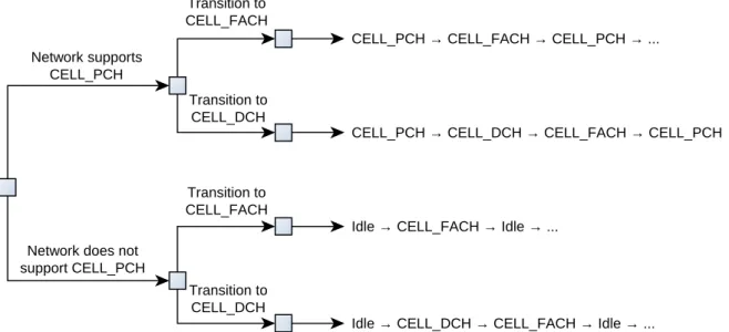
If a device sends a single keepalive message toward a destination host, there are a few possible state transitions to consider, which are illustrated in the decision tree in Figure 4.3. Transitioning to CELL_FACH or CELL_DCH depends on the network configuration. Is it assumed that, before sending a keepalive, the device is in Idle mode or CELL_PCH state and that no other data packets are sent over the network at that time.
If a user application sends a keepalive that should be acknowledged (such as a TCP keepalive, or an application keepalive over UDP), then the device may have to return to a higher RRC state or repeat the cycle of state transitions again, depending on the round-trip time of that keepalive. In case the round-trip time is greater than the timer for the active RRC state the device is currently in (CELL_DCH or CELL_FACH), the device transitions to a lower state and, upon receiving the acknowledgment, back to the higher state. This increases the power consumption of the device and generates more signaling traffic due to more state transitions.
4.3. Conclusions
With an increasing amount of smartphones connected to mobile networks, the amount of signaling traffic increases significantly, especially considering the widespread usage of always-on applications such as social networks or instant messaging. One cause of the increased signaling overhead is the frequent transmission of keepalives, which generates signaling messages due to RRC state transitions of mobile devices. The increased signaling overhead imposes considerably
Figure 4.3: Possible RRC state transitions when sending a single keepalive
CELL_PCH → CELL_FACH → CELL_PCH → ...
CELL_PCH → CELL_DCH → CELL_FACH → CELL_PCH → ...
Idle → CELL_FACH → Idle → ...
Idle → CELL_DCH → CELL_FACH → Idle → ... Network supports
CELL_PCH
Network does not support CELL_PCH Transition to CELL_DCH Transition to CELL_FACH Transition to CELL_FACH Transition to CELL_DCH
higher processing requirements on mobile network elements and may eventually cause slower data rate or network congestion.
Due to sending keepalives frequently, mobile devices remain longer in the active RRC states (CELL_DCH and CELL_FACH), which contributes to higher battery power consumption of mobile devices.
A new concept in the field of computer networks called software defined networking (SDN) has a great potential of improving the effectiveness and scalability of computer networks, including mobile networks. SDN is discussed in the next chapter.
5. Software Defined Networking
Software defined networking (SDN) is a relatively new concept in the field of computer networks. SDN emerged from the requirements of enterprises and end users that today's traditional networks cannot cope with [32] [33].
The main idea of SDN is to separate the control and the data planes of network nodes. The control plane is logically centralized in an element called the controller and the data plane remains in the network nodes, which are now called forwarders. Forwarders usually perform packet forwarding and basic packet processing, such as overwriting fields in packet headers [34].
Figure 5.1 shows the basic architecture of SDN networks [34]. The controller manages forwarders via a standard communication interface, such as OpenFlow15 or NETCONF [35]. This is also called the southbound interface. Network applications are software programs that define the network behavior (hence the term “software defined networking”), ranging from very basic programs, such as packet switching, to more advanced applications, such as a firewall. The controller accepts requests from the network applications and translates them to low-level commands that the forwarders are able to process. Each network application communicates with the controller via a separate northbound interface.
In general, SDN networks have the following advantages over traditional networks [32] [33]: 15 More information at:
https://www.opennetworking.org/sdn-resources/openflow/57-sdn-resources/onf-specifications/openflow?layout=blog
Figure 5.1: SDN architecture overview
Controller
Forwarder Forwarder Forwarder
Network application Network application
Data Plane Control Plane Application Plane
Northbound interfaces
• ease of adding new or modifying existing network applications, • improved automation and management of network devices,
• given the standard communication protocol between the controller and the forwarders, network devices from multiple vendors can be deployed in networks,
• improvement of the user experience due to the ability of SDN networks to easily adapt to the needs of end users.
Migration from a traditional network to a pure SDN network may be costly. Is it not uncommon to for hybrid SDN networks to exist that contain a mix of traditional network elements, forwarders and one or more controllers [32].
5.1. OpenFlow
OpenFlow is a popular standard for communication between a controller and forwarders. Forwarders are referred to as OpenFlow switches. OpenFlow protocol and switch are defined by the OpenFlow switch specification [36].
At the time of writing this thesis, the most recent version of the OpenFlow specification is 1.5.1 [37]. Given that the solution described in this thesis uses SDN controller and forwarder software compatible with OpenFlow 1.3.0, this section discusses the OpenFlow specification 1.3.0 [36]. This section covers only the components of an OpenFlow switch used in the thesis.
5.1.1. OpenFlow Switch Overview
Figure 5.2 shows the basics of an OpenFlow switch. The switch communicates with the controller via the OpenFlow protocol. When a packet is received on an ingress port, it is processed through a set of flow tables. The packet processing is also called the pipeline. Each flow table contains a set of rules called flow entries.
Datapath refers to a part of the OpenFlow switch that comprises the ports, flow tables and the pipeline. Control channel refers to the communication interface between the switch and the controller. Each datapath is defined by a unique 64-bit datapath ID. The lower 48 bits define the
Figure 5.2: Overview of an OpenFlow switch (forwarder) OpenFlow switch
Flow table 0 Flow table 1 ... Flow table n Switch pipeline
Controller
Packet in Packet out
MAC address of the switch and the upper 16 bits are implementation-specific [36].
5.1.2. Communication with Controller
The communication of the OpenFlow switch and the controller is provided by the control channel. Using the control channel, the controller and the switch exchange control messages or forward data packets to and from the controller.
The message delivery between the controller and the switch is guaranteed. There is no need for a network application to explicitly check and acknowledge that a message sent from the controller to the switch was received successfully.
Features message is sent by the controller during the establishment of the control channel to query the switch about its capabilities. Modify-State messages are sent by the controller to add, modify or remove flow entries or to modify the properties of ports. Packet-Out messages are used by the controller to send packets through the switch to the destination. Packet-In messages are sent by the switch to forward packets to the controller (via the reserved CONTROLLER port).
If a controller installs a flow entry on a switch with the OFPFF_SEND_FLOW_REM flag set and the flow entry expires or is deleted by the controller, the switch informs the controller that the flow entry has been removed by sending a Flow-Removed message to the controller.
5.1.3. Flow Entries
Each flow entry contains components shown in Figure 5.3.
Match fields determine whether a packet matches the flow entry. If so, the instructions for this flow entry are executed. Match fields may contain the following [36]:
• ingress port ID,
• header fields (e.g. EtherType from the Ethernet frame header, Time To Live from the IPv4 header),
• metadata specified by a previous table.
A match for a flow entry must contain all its associated prerequisites. For example, to match a UDP datagram with a specified destination port, the match must also contain the corresponding lower-layer protocols – in this case, EtherType field for IPv4 (0x0800) and IPv4 Protocol field for UDP (0x11). If the prerequisites are not specified, the switch sends an error message to the
controller with OFPET_BAD_MATCH type and OFPBMC_BAD_PREREQ flags set. A flow entry that matches any packet and has priority equal to 0 is called the table-miss flow entry.
Priority defines the precedence of a flow entry. If a packet matches multiple flow entries, only the flow entry with the highest priority is considered and other entries are discarded. If there are
Figure 5.3: Flow entry structure in an OpenFlow switch
multiple flow entries with the same priority, the behavior of the switch is undefined (not even OpenFlow 1.5.1 defines this behavior). It is assumed that this behavior is defined by a concrete implementation of the switch software. The controller may prevent adding flow entries with the same priority and intersecting matches by setting the OFPFF_CHECK_OVERLAP flag in Modify-State messages.
Counters are incremented every time a packet matches the flow entry. Examples of per-flow-entry counters include the number received packets or received bytes. Other types of counters are defined e.g. per flow table or per port.
If a packet matches the flow entry, a set of instructions is executed. Instructions are discussed in section 5.1.4.
Timeouts are optional and are used by the controller to set the flow entry to expire after a specified amount of time in seconds. If hard_timeout is set, the flow entry expires after the specified number of seconds since its addition to the switch. If idle_timeout is set, the flow
entry expires after the specified number of seconds if no packet matched this flow entry for
idle_timeout seconds.
Cookie is a value that the controller associates with the flow entry. Cookie can be used by the controller to filter messages dealing with flow modification, flow deletion or flow statistics.
5.1.4. Instructions
Generally speaking, instructions modify the packet, the set of actions or the pipeline processing. Commonly used instructions are the following:
• Write-Action – adds the specified actions into the action set.
• Apply-Actions – applies the action set to the packet immediately, without modifying the action list. This can be used to execute the action set multiple times.
• Clear-Actions – clears the action set.
• Goto-Table – causes the pipeline to jump to the flow table specified by its ID. The flow table ID must be greater than the current flow table ID.
Actions
The action set is a list of actions applied to the packet. The action set can be modified by instructions, such as those mentioned above. Some commonly used actions include:
• Set-field – modify a header field. While this action is not specified as mandatory in the OpenFlow switch specification, its inclusion in the implementations of OpenFlow switches greatly improves the usefulness of the switches. The set-field action allows to overwrite IP addresses and ports, thus allowing to implement a simple NAT.
• Output – send the packet out the specified port.

![Table 4.1: Average current (power consumption) of a mobile device in RRC states [30] [5] [29]](https://thumb-us.123doks.com/thumbv2/123dok_us/9952642.2889917/35.892.188.710.100.558/table-average-current-power-consumption-mobile-device-states.webp)
![Figure 5.1 shows the basic architecture of SDN networks [34]. The controller manages forwarders via a standard communication interface, such as OpenFlow 15 or NETCONF [35]](https://thumb-us.123doks.com/thumbv2/123dok_us/9952642.2889917/38.892.103.795.572.985/architecture-networks-controller-forwarders-standard-communication-interface-openflow.webp)
