INSTRUCTION AND REPAIR MANUAL
VERTICAL TURBINE
VERTICAL TURBINE MODELS
PUMP IDENTIFICATION
Carefully record all of the following data from your pump nameplate. It will aid in obtaining the cor-rect replacement parts for your pump. In addition to the nameplate, the pump serial number is stamped on the discharge flange.
Pump: Serial Number ___________ GPM ___________
Pump Size ___________ Head (PSI) ___________
Model Number ___________
Number of Stages ___________
Motor: Manufacturer ___________ Horsepower ___________
Serial Number ___________ Motor Frame ___________
Full Load Speed ___________ Full Load Amps ___________
Phase/Hz/Volts ___________ Date in Service ___________
Engine: Manufacturer ___________ Horsepower ___________
RPM ___________ Serial Number ___________
Model Number ___________ Date in Service ___________
Gear: Manufacturer ___________ Serial Number ___________
Model Number ___________ Ratio _____ : _____
Rotation Figure # 1
Controller: Manufacturer ___________ Serial Number ___________
VERTICAL TURBINE MODELS 10FEM THRU 19FGHF - VERTICAL TURBINE
FIRE PUMPS
INSTALLATION, OPERATION AND MAINTENANCE TABLE OF CONTENTS Warranty Highlights . . . .4 Introduction . . . .5 Section 1 General Safety . . . .6 Storage of Pumps . . . .7
Consider a Unit in Storage . . . .7
Assembled Pumps . . . .7 Unassembled Pumps . . . .7 Section 2 Introduction General Description . . . .8 Bowl Assembly.. . . . .8 Column Pipe….. . . .8 Line Shafting….. . . . .8 Discharge Heads . . . .8 Drivers . . . .8 Section 3 Installation General . . . .9 Foundation . . . .9
Well and Pit Inspection . . . .9
Bowl Assembly . . . .10
Suction Strainer . . . .10
Leveling and Grouting . . . .10
Hoisting and Piping . . . .11
Pump Assembly . . . .11
Product Lubricated Open Line Shaft . . . .13
Oil Lube Enclosed Line Shaft . . . .14
Driver Installation . . . .17
Vertical Hollow Shaft Drivers . . . .17
Section 4 Operation General . . . .19
Before Starting the Pump . . . .19
Initial Startup . . . .19
Normal Operation . . . .20
Shutdown . . . .20
Troubleshooting . . . .20
Pump Symptoms . . . .20
Insufficient Pressure or Flow . . . .20
Loss of Suction Operation . . . .21
Excessive Power Consumption . . . .21
Vibration or Noise . . . .21
Execessive Packing Box Leakage . . . .21
Over-Heating . . . .21
Driver / Controller Symptoms . . . .21
Driver Does Not Start . . . .22
Driver Fails To Come Up To Speed. . . . .22
Motor Runs Hot . . . .22
Motor Vibrates . . . .22 Driver Is Noisy . . . .22 Incorrect Rotation. . . . .22 Section 5 Maintenance Preventive Maintenance . . . .22 Grease Recommendation . . . .23 Packing Adjustment . . . .23 Packing Replacement . . . .23 Pump Disassembly . . . .24 Driver Removal . . . .24
Vertical Hollow Shaft(VHS) Driver . . . .24
Discharge Head Removal . . . .24
Column Removal . . . .24
Pump Bowl Disassembly . . . .25
Inspection for Replacement . . . .26
Shaft Straightness . . . .27
Pump Bowl Assembly . . . .27
Wear Rings . . . .28
Assembly Tools . . . .29
Maintenance History . . . .31
Maintenance Notes . . . .32
Section 6 Repair Parts Ordering Parts . . . .33
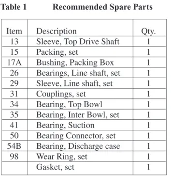
Recommended Spare Parts . . . .33
Returning Parts . . . .33
Service . . . .33
Warranty Service . . . .33
Service After Warranty . . . .33
Section 7 Reference Information Technical Data………. . . .34
Figures . . . .37
Drawings and Diagrams . . . .39
WARRANTY HIGHLIGHTS
1. Seller warrants products of its own manufacture against defects in materials and workmanship under normal use and service for one (1) year from date of installation orstart-up, but not more than eighteen (18) months after date of shipment.
2. Accessories and components not manufactured by seller are warranted only to the extent of the original manufacturer's warranty.
3. No allowances will be made for repairs or alterations effected without specific written authorization from Seller.
4. The equipment as manufactured by Aurora Pump is precision machinery. Proper care can give a lifetime of satisfactory service. Guarantees of performance and warranties are based on the use of original equipment manufactured (OEM) replacement parts. Aurora Pump assumes no responsibility when alterations, non-authorized design modifications and/or non-OEM replacement parts are incorporated.
5. This warranty is VOID unless the purchaser provides protective storage, installs and maintains the equipment in accordance with manufacturer's instructions.
6. Under the terms of this warranty, Seller shall not be responsible nor liable for: a. Consequential, collateral or special losses or damages.
b. Equipment conditions caused by fair wear and tear, abnormal conditions of use, accident, neglect, or misuse of said equipment.
c. Labor charges, loss or damage resulting from supplying of defective part(s) or improper repairs by unauthorized person(s).
d. Damage caused by abrasive materials, chemicals, scale deposits, corrosion, lightning, improper voltage or mishandling.
e. Labor charges for installation, removal or reinstallation of equipment.
7. The above listed warranty highlights do not constitute our total terms and conditions regarding warranty. For complete warranty information please refer to complete warranty statement herein.
LOSS OR DAMAGE IN TRANSIT
Immediately upon receipt a complete inspection and accounting against the packing list should be made of all major components, and accompanying boxes or pallets.
All material is shipped F.O.B. our factory, or our vendor's shipping point unless other, contractual, arrangements are made. Under these terms, any claims for loss or damage in transit should be immedi-ately directed to the delivering freight carrier.
The factory will assist the customer in receiving fair compensation, but assumes no responsibility to mediate such claims. This policy includes shipments wherein Aurora Pump pays freight costs as part of the sales terms.
INTRODUCTION
Congratulations! You are the owner of the finest pump commercially available. If you give it the proper care as outlined and recommended by this manual, it will provide you with reliable service and long life.
This manual applies to the pump installation, operation and maintenance. If your operating conditions ever change, always refer to the fac-tory for reapplication. Always refer to the man-uals provided by manufacturers of the accessory equipment for their separate instructions.
Variations exist in both the equipment used with these pumps and in the particular installation of the pump and driver. Therefore, specific operat-ing instructions are not within the scope of this manual. This manual contains general rules for installation, operation and maintenance of the pump. If there are questions regarding the pump or its application which are not covered in this manual, please contact the factory as follows:
Kansas City, Kansas: Aurora Pump 3601 Fairbanks Avenue PO Box 6999 Kansas City, KS 66106 Tel: (913) 748-4253 Fax: (913) 748-4030
To obtain additional data on hydraulics and pump selection and operation, we suggest you purchase the following reference books:
1. Hydraulic Institute Standards Hydraulic Institute 9 Sylvan Way
Parsippany, NJ 07054-3802
2. Fairbanks Morse Hydraulic Handbook Aurora Pump
3601 Fairbanks Avenue PO Box 6999
Kansas City, KS 66106
3. National Fire Protection Association NFPA Pamphlet 20 & 25
1 Batterymarch Park PO Box 9101
Quincy, MA 02269
4. Underwriters Laboratories, Inc. Underwriters Laboratories, Inc. 333 Pfingsten Road Northbrook, IL 60062 5. Factory Mutual Factory Mutual 1151 Boston-Providence Turnpike PO Box 9102 Norwood, MA 02062 IMPORTANT
Read this complete manual and manuals for all component equipment before assembly or installation is started. It contains information which is the result of engineering and research efforts. It is designed to supply ade-quate instruc-tions for the installation, opera-tion and maintenance of your pump. Failure or neglect to properly install, operate or maintain your pump may result in personal injury, property damage or unnecessary damage to the pump.
SECTION 1 GENERAL
Safety
Safety should be of utmost importance when in close proximity of this pumping equipment. Before attempting to operate this equipment, you should read this manual in its entirety, tak-ing special notice of all cautions, warntak-ings and/or danger notifications. These warnings apply to pumps supplied by Aurora Pump. Refer to the manuals supplied by the driver and control manufacturer for additional warnings before operating this equipment.
The words DANGER, WARNING and CAU-TION have different connotations and are gen-erally defined as follows:
The installation, use and operation of this type of equipment is affected by various Federal, State and Local Laws and the regulations con-cerning OSHA. Compliance with such laws relating to the proper installation and safe oper-ation of this type of equipment is the responsi-bility of the equipment Owner and all necessary steps should be taken by the Owner to assure compliance with such laws before operating the equipment.
DANGER
Indicates an imminently hazardous situation which, if not avoided, will result in death or serious injury.
WARNING
Indicates a potentially hazardous situation which, if not avoided, will result in serious injury.
CAUTION
Indicates a potentially hazardous situation which, if not avoided, may result in minor or moderate injury or may indicate that improper practices will result in equipment malfunction or failure. It may also be used to alert against unsafe practices.
IMPORTANT
Indicates the highlight or accent of specific information.
NOTE
Specific information useful in maintaining the equipment.
DANGER
Do not attempt to service the pump until the electrical power has been disconnected and it has been verified that the pump cannot start. Because many installations utilize automatic starting equipment, the pump unit may start at any time without warning. Proper precau-tions should be taken to avoid injury as a result of automatic starting of the equipment.
DANGER
Do not operate the pump without guards in place over the rotating parts. Exposed rotat-ing parts can catch clothrotat-ing, frotat-ingers, or tools, causing severe injury to personnel. Any operation of this machine without a protec-tive guard can result in severe bodily injury. The responsibility for the installation of pro-tective guards is that of the equipment owner.
DANGER
This pump is designed for the exclusive use of pumping water. It should not be used for pumping other media unless a specific Purchase/Buyer agreement is negotiated.
WARNING
Do not attempt to try to clean the pump with bare hands. The pumped material may con-tain items that may present health hazards such as needles, and other sharp objects. Always wear heavy puncture resistant gloves.
Before attempting to service this pump:
1. Familiarize yourself with this manual. 2.Disconnect or lock out the power source to
insure the pump will not start. Confirm power source disconnect with appropriate electrical test equipment.
3. Close the discharge valve.
After the pump has been installed, make certain that the pump and all piping connections are tight and are properly supported prior to start-up and operation.
Storage of Pumps
CAUTIONIf the equipment is not to be immediately installed and operated, THE FOLLOWING INSTRUCTIONS SHOULD BE ADHERED TO AS A MINIMUM:
Consider a unit in storage when:
1. It has been delivered to the job site and is awaiting installation.
2. It has been installed but operation is delayed pending completion of plant construction. 3. There are long (30 days or more) periods
between operation cycles.
4. The plant (or facility) is shut down.
Assembled Pumps:
1. Remove the gland halves, packing and seal water rings from the stuffing box if the pump is so equipped.
2. When pumps with rubber bearings are stored assembled in horizontal position, it is neces sary to rotate the entire pump and column assembly 90 degrees once per month. This practice will help prevent the weight of the shafts from deforming the rubber bearings. Pumps with metal bearings stored in horizon tal positions are to have shafts rotated once per month to prevent line shafts from deform ing or bowing under their own weight. 3. Pumps stored fully assembled and installed
are to be rotated once per week to prevent brinelling of motor thrust bearings. Packing or mechanical seals are to be serviced as noted above.
Unassembled Pumps:
1. Store the unassembled components in a clean, dry well-ventilated place free from vibrations, moisture, and temperature varia tion.
2. Wipe clean all exposed machined surfaces and coat with a heavy layer of grease or other equivalent rust preventative material.
3. Cover the suction and discharge of the pump with cardboard or wood to prevent entry of foreign material or varmints. This also applies to column sections.
4. The bearings, shaft, and couplings should be stored as components, i.e., shaft with cou plings installed on lower ends. The ends should then be wrapped with heavy plastic or protective material and secured tightly to pre vent entry of foreign matter and varmints.
WARNING
Certain procedures in disassembly and assem-bly require parts be heated to high tempera-tures. Heat resistant gloves must be worn when handling heated parts. Heated parts can cause severe personal injury.
CAUTION
For pumps used in potable water service, all thread lubrication, grease, cleaning materials and paint must be suitable for potable water. Do not attempt to try to clean the pump with bare hands.
NOTE
Improper storage could result in product fail-ures or restoration not covered by warranty.
SECTION 2 INTRODUCTION
General DescriptionA vertical line shaft turbine fire pump consists of five basic components. These components are the pump bowl assembly, column pipe, line shafting, discharge head, and driver. Refer to the drawing section for general arrangement drawings.
Bowl Assembly
The multi-stage bowl assembly is made up of a suction bell, multiple intermediate bowls and impellers. Multiple stage open line shaft con-struction does not require a discharge case. Refer to the assembly drawing found in the drawing section of this manual for your specific configuration.
Column Pipe
Column pipe for pumps covered in this manual can be either threaded or flanged. Threaded column features straight threads on both column ends and butt solidly together within the cou-pling. Standard nominal column lengths for threaded column are 5 foot, 10 foot or any spe-cial length up to 10 foot.
Flanged column includes registered fits for accurate column alignment and are bolted together. Flanged column pipe is available in standard lengths of 10 foot or 5 foot; or can be provided in any special length up to 10 foot.
Line Shafting
The turbine line shaft transmits torque from the pump driver to the pump bowl assembly and rotates inside the column pipe. Both ends of the shaft are precision machined, and are secured together with couplings. This shafting is sup-ported by bearings at specific intervals; the types of bearings used and how they are lubri-cated are described as follows:
A. Open Line Shaft - Product Lubricated This design is such that the line shaft and bearings are exposed to and lubricated by the
liquid being pumped. The line shaft is sup ported at intervals of not more than 10' by bearings that run on shaft sleeves. Support for these bearings is supplied by bearing retainers. The outer hub of the retainer is seated between the two column ends. Refer to the specific assembly drawings found in the drawing section of this manual.
B. Enclosed Line Shaft
In the enclosed line shaft design shafting is surrounded by tubing. This tubing protects both the shaft and bearings from the pumped liquid and provides a channel for lubricating the shaft bearings. The bearings have machined grooves on their I. D. to allow lubrication to flow from one bearing to the next. These bearings are also threaded on the outside diameter to connect the five foot enclosing tube sections. Lubrication is oil from a separate source. The enclosing tube will be supported by spiders unequally spaced to reduce the risk of vibration when the com bined shaft length exceeds 30 feet.
Discharge Heads
Discharge heads perform multiple functions: direct the pump flow from the pump column to the discharge piping system, provide a method for sealing the line shaft, provide a base from which the pump is suspended, and provide a mounting surface for the driver.
Surface discharge heads incorporate both the discharge elbow and driver pedestal in one piece. The bottom surface of the discharge head is machined to mate with the sole plate.
Drivers
A variety of driver sizes and types can be sup-plied based on the specific job requirements. Drivers must be a vertical motor for electric driven or a diesel engine connected through a right angle gear.
The electric motor or right angle gear drive must be of the “hollow shaft” configuration. In
this configuration, the line shaft passes through the hollow drive tube of the motor or gear. The motor or gear top shaft is locked to the motor or gear coupling by a gib key and held in proper vertical position by an adjusting nut. Refer to your submittal package for your specific pump driver configuration.
SECTION 3 INSTALLATION
GeneralPrior to assembly and/or installation, the pump and loose parts are to be inspected for com-pleteness, correctness and cleanliness. During this inspection, all parts are to be thoroughly cleaned and any burrs removed by filing. The pump bowl assembly, including the line shaft coupling, is normally shipped completely assembled. Both the suction and discharge openings should be inspected for damage and for foreign materials. Rotate the shaft by hand, and move in and out to check for end play. Place all parts in an orderly arrangement for convenient assembly.
Foundation
A foundation must be supplied consisting of any material that will provide a permanent, rigid support. This support is to be of sufficient size and depth to fully carry the weight of the pump (full of water) and rigid enough to pre-vent vibration.
Anchor bolts are to be supplied and set in place by the installing contractor. Anchor bolts of appropriate size, length and configuration are required to adequately secure the discharge head/pedestal to the foundation.
When the pump is to be mounted over a pit on structural steel framing, it should be located as close to the main structure or wall as possible. Cross members are to be used to prevent distor-tion and vibradistor-tion of structural mounting frame.
Well and Pit Inspection
Prior to installation and start-up, the well or pit must be cleaned of all loose material and debris. Both the suction and discharge openings should be inspected for damage and for foreign materi-als. Insure that trash racks and strainers have been installed in accordance with NFPA20 requirements.
CAUTION
Turbine pumps are shipped with a shaft retention bolt installed in the suction bell to protect the pump from damaging shaft movement during transit. It is imperative that the retaining bolt be removed, and grease added (if not already packed) to lower bearing cavity. Install the suction bell plug prior to pump installation. Failure to follow these instructions will result in seri-ous damage to the pump. Read and heed all warning tags and labels.
WARNING
Extreme caution is to be exercised when hoist-ing components with open lifthoist-ing lugs. Precautions should be taken to prevent hoisting slings from coming out of the lugs.
WARNING
Never attempt to mount the driver on the dis-charge head prior to installation of the pump.
WARNING
Never attempt to hoist the entire pump by the driver lifting lugs or eyes. These lifting points are designed only to hoist the weight of the driver, not other attached components.
IMPORTANT
All shafting has been pre-straightened to a tolerance of 0.005" in 10 feet prior to leaving the factory or assembly plant. Care in han-dling must be taken to insure that the shafting is not bent prior to and during installation. (Refer to page 27 for shaft straightening instructions.)
Bowl Assembly
Shaft projectionis defined as the distance from the discharge bowl mounting surface (flange seat for flanged column, thread seat for thread-ed column) to the end of the pump shaft. Nominal standard shaft projection for models 10FEM, 11FGM, 12FCM, 13FGH, & 15FGH is 17-1/2". Nominal standard shaft projection for models 19FGM & 19FGH is 12”. Since all applicable bowl assemblies are shipped with the pump shaft bolted in its lower most position, projection is measured with the impellers rest-ing at the bottom of their axial travel.
Shaft end play is the amount of axial move-ment available in the pump bowl assembly. After removing the shaft retaining bolt, measure and record the pump bowl end play. This can
most easily be accomplished with the bowl assembly in a horizontal position. Grasp the pump shaft and move the shaft through its max-imum axial travel. Consult Table #1 in the Technical Data Section to assure that the dis-tance measured complies with the specifications for your pump model.
A discharge case is included for oil lubricated enclosed line shaft bowl assemblies.
Suction Strainer
A suction strainer is to be used, it is to be attached to the suction bell.
Leveling and Grouting
Prior to the pump installation, the foundation plate must be leveled and grouted in place.
The foundation plate is to be lowered onto the anchor bolts and leveled. This can be achieved by applying a good quality machinist’s spirit level to the machined surface of the foundation plate.
After leveling, the foundation plate is to be grouted in place with a good quality non-shrinking grout. After the grout is fully dry, the foundation plate is to be nutted solidly in place against the grout bed.
Leveling devices are to be removed or backed off and the pump foundation plate tightened solidly against the grout bed. All pockets and/or holes left by removal of leveling devices are to be filled with grout.
CAUTION
Reduced performance and possible equipment damage may result from ingestion of foreign material by the pump.
CAUTION
Turbine pumps are shipped with a shaft retention bolt installed in the suction bell to protect the pump from damaging shaft move-ment during transit. It is imperative that the retaining bolt be removed, and grease added (if not already packed) to lower bearing cavi-ty. Install the suction bell plug prior to pump installation. Failure to follow these instruc-tions will result in serious damage to the pump. Read and heed all warning tags and labels.
NOTE
Before proceeding, measure and record the pump bowl assembly end play. This informa-tion will be needed later.
CAUTION
Always remove the shaft retaining bolt before installing or operating the pump.
CAUTION
Should you receive a bowl assembly for enclosed line shaft oil lubricated construc-tion that has two pipe plugs installed in the discharge case, THESE PIPE PLUGS MUST BE REMOVED PRIOR TO INSTALLATION. Failure to remove the plugs will cause water to enter the enclosing tube and leak out at the discharge head. Bearing failure may result.
Hoisting and Piping
If your pump was shipped completely assem-bled, it is now ready to install.
The pump is to be hoisted by the discharge head. Pumps thirty feet or more in overall length should also be supported at the column midpoint to avoid column/shaft distortion and possible pump damage. The pump is to be low-ered onto the foundation plate and aligned with the pump mounting holes. The pump is to be secured to the foundation plate with the provid-ed bolting.
Piping is to be brought in direct axial alignment with the pump discharge. Flange faces are to fit closely and squarely. The pump discharge is to have no strain imposed upon it by piping mis-alignment.
Pump Assembly
If the pump has been shipped dis- assembled, the following instructions are to be employed to assemble the unit vertically in the well or sump. Determine if the pump to be assembled is Product Lubricated Open Line Shaft or Oil Lube Enclosed Line Shaft. Prior to assembly,
all components are to be identified and laid out in order of assembly. Standard length (5’ or 10') intermediate column, and shaft are inter-changeable and can be assembled in any order. However, shorter non-standard column and shaft sections are provided to accomplish the required overall pump length, and must be installed at the top of the pump directly under the discharge head. The top enclosing tube also has longer threads to engage the top tube ten-sion nut.
On threaded column, all column couplings are to be installed on the upper end of the column prior to lifting. This will provide a stop for pipe clamps during the hoisting process.
Product Lubricated Open Lineshaft with Flanged Column
A. Using an appropriate hoisting system, lift the bowl assembly into position over the well. Lower the bowl partially into the well. Attach a pipe clamp (see Figure #1) to the upper most bowl directly under the bowl dis charge flange. Lower the assembly, allowing it to be supported on the foundation via the pipe clamp.
B. Lift the first section of pre-assembled col umn & shaft into position over the suspended bowl assembly (see Figure #2). Care is to be taken not to damage the threads on the pump shaft or line shafts. Clean the threads and lubricate with appropriate thread lubricant. A line shaft coupling should already be in place on the pump shaft. Thread the line shaft into the coupling.
IMPORTANT
Damaging vibration may result if the foun-dation plate is not solidly in contact with the grout bed. Even the highest quality non-shrink grouts contract slightly during drying. All leveling wedges, nuts or jackscrews are to be removed or backed off prior to final torquing of the foundation plate fasteners. Failure to do so will result in the pump foun-dation plate resting on the leveling devices rather than the grout bed.
WARNING
The pump is to always be lifted using ade-quate crane and sling capacity. All applicable safe hoisting practices should be employed.
IMPORTANT
Line shaft threads are left hand. Tighten shafts and couplings securely with pipe wrenches.
Assure that no burrs or foreign matter exists on the coupling or on the shaft threads. The threaded shafts are to butt together solidly and squarely in the center of the coupling. Both shafts are to be equally engaged in the coupling threads. Threads should be exposed on both ends of the coupling.
C. Lower the column onto the bowl discharge flange. All column joints should be coated with non-hardening gasket sealant such as Loctite PST #567, Permatex No. 2 or equal. Silicon sealants are also permissible. Install bolts and nuts and tighten.
D. The line shaft is to project out beyond the end of the installed column. Install the bear ing retainer assembly over the shaft projec tion. Seat the retainer OD in the column flange counterbore.
E.Lift the column/bowl assembly slightly and remove the pipe clamp from the bowl. Lower the assembly and reinstall the pipe clamp below the upper column flange. Lower the assembly so the pipe clamp suspends the assembly on the foundation.
F. Install the next shaft and column segment as previously instructed assuring that its lower flange counterbore engages the top of the bearing retainer OD. Coat the column coun terbores with sealant prior to installation.
Install bolts and nuts and tighten. A slight gap will remain between the two column flanges. This condition allows the bearing retainer to be clamped securely between the flanges. G. Continue subsequent shaft and column
assembly until complete. Continue to mea sure the shaft projection after assembly of each shaft/column section.
H. For ease of installation and reduce the possi bility of bushing damage, remove the packing box if shipped assembled to the discharge head.
I. Install column flange gasket (when used) and secure the discharge head to the last column flange. When attaching the column to the dis charge head, make sure the register fit is fully engaging the head.
J. After attaching the column to the discharge head remove the column clamp, and lower the unit to the foundation plate and tighten mounting bolts. Check the shaft to see if it is centered in the packing box opening in the head. If the shaft is not centered, it could be an indication of a bent shaft, column not seat ed properly, or the unit is not properly plumbed. Any or all of these problems must be corrected before proceeding with the installation of the unit.
K Apply lubricant to the packing box bushing and install the packing box on the discharge head.
L.Install the packing and glands into the pack ing box. Install gland bolts and nuts. Allow the gland nuts to remain loose. Final packing adjustment will be with the pump operating.
NOTE
Replaceable wear sleeves must be posi-tioned to engage line shaft bearings. The presence of any foreign material between the shaft ends will cause shaft misalign-ment and will result in vibration or acceler-ated bearing wear.
IMPORTANT
Measure the shaft projection. It should con-form to the shaft projection measurement recorded previously on the bowl assembly.
NOTE
Coat the column counterbore with sealant prior to a retainer installation.
NOTE
Neoprene rubber line shaft bearings should NOT be lubricated. Lubrication of neo-prene rubber bearings may cause distortion or swelling.
NOTE
Standard shaft and column lengths are 5 or 10 feet. Non-standard lengths of shafts and column may be used to accomplish the required overall pump length. Non-standard shaft/column sections will always be assembled at the top of the pump, directly under the discharge head.
Product Lubricated Open Lineshaft with Threaded Column
1. Using an appropriate hoisting system, lift the bowl assembly into position over the well. Lower the bowl partially into the well. Attach a pipe clamp (see Figure #1) to the upper most bowl directly under the bowl flange. Lower the assembly, allowing it to be sup ported on the foundation via the pipe clamp. 2. Lift the first section of pre-assembled column
& shaft into position over the suspended bowl assembly (see Figure #2). Care is to be taken not to damage the threads on the pump shaft or line shafts. Clean the threads and lubricate with appropriate thread lubricant.
A line shaft coupling should already be in place on the pump shaft. Thread the line shaft into the coupling.
3. Lower the column and thread it into the bowl assembly until it solidly and squarely butts together with the bowl, tightening with appropriate wrenches.
4. Lift the column/bowl assembly slightly and remove the pipe clamp from the bowl. Lower the assembly and reinstall the pipe clamp below the upper column threads. Lower the assembly so the pipe clamp suspends the assembly on the foundation.
The line shaft is to project out beyond the end of the installed column.
5. Slide the bearing retainer with bearing over the shaft projection and lower into the col umn coupling. Install the shaft coupling and next section of shaft/column assembly as pre viously outlined.
6. Continue subsequent shaft and column assembly until complete. Continue to mea sure the shaft projection after assembly of each shaft/column section.
IMPORTANT
Line shaft threads are left hand. Tighten shafts and couplings securely with pipe wrenches. Assure that no burrs or foreign matter exists on the coupling or on the shaft threads. The thread-ed shafts are to butt together solidly and square-ly in the center of the coupling. Both shafts are to be equally engaged in the coupling threads. Threads should be exposed on both ends of the coupling.
NOTE
Replaceable wear sleeves must be positioned to engage line shaft bearings. The presence of any foreign material between the shaft ends will cause shaft misalignment and will result in vibration or accelerated bearing wear.
IMPORTANT
Assure that no burrs or foreign matter exists on the column coupling threads or on the column threads prior to assembly. All joints are to be coated with sealant prior to assembly. The col-umn sections should butt together solidly and squarely in the middle of the column coupling. Secure each joint firmly with appropriate
wrenches. ALL COLUMN THREADS ARE
RIGHT HAND ROTATION.
IMPORTANT
Measure the shaft projection. It should conform to the shaft projection measure-ment recorded previously on the bowl assembly.
NOTE
Coat the column counterbore with sealant prior to a retainer installation.
NOTE
Neoprene line shaft bearings should NOT be lubricated. Lubrication of neoprene bearings may cause distortion or swelling.
NOTE
Standard shaft and column lengths are 5 or 10 feet. Non-standard lengths of shafts and column may be used to accomplish the required overall pump length. Non-stan-dard shaft/column sections will always be assembled at the top of the pump, directly under the discharge head.
7. For ease of installation and reduce the possi bility of bushing damage, remove the packing box if shipped assembled to the discharge head.
8. If supplied with a SDC model discharge head, thread the top column directly into the thread ed connection of the head and tighten with appropriate wrenches. If supplied with a LAD model discharge head, thread the top column adapter flange onto the top column and tighten with appropriate wrenches. Install column flange gasket and secure the discharge head to the column adapter flange. When attaching the column to the discharge head, make sure the register fit is fully engag ing the head and the flange is timed with the pipe tapped hole in the discharge head. 9. After attaching the column to the discharge
head, remove the column clamp and lower the unit to the foundation plate. Tighten mounting bolts. Check the shaft to see if it is centered in the packing box opening in the head. If the shaft is not centered, it could be an indication of a bent shaft, column not seat ed properly, or the unit is not properly plumbed. Any or all of these problems must be corrected before proceeding with the installation of the unit.
10. Apply lubricant to the packing box bushing and install the packing box on the discharge head.
11. Install the packing and glands into the pack ing box. Install gland bolts and nuts. Allow the gland nuts remain loose. Packing adjust ment will be performed later with the pump operating.
Oil Lubricated Enclosed Lineshaft with Flanged Column
1. Using an appropriate hoisting system, lift the pre-assembled bowl assembly and position it above the well. Lower the bowl assembly partially into the well and attach a pipe clamp (see Figure #1) to the upper most bowl direct ly under the bowl discharge flange. Lower the assembly, allowing it to be suspended on the foundation plate via the pipe clamp.
2. Before proceeding with assembly, lay out all line shaft, enclosing tube, spiders (if
required), column and connectors. Inspect and identify all items and arrange them in the order in which they will be assembled. Oversized diameter enclosing tube sections (if used) must be installed at the bottom of the assembly, directly above the pump dis charge bowl. When oversized tube sections are used, special stepped connector bearings are provided in order to adapt them to the remaining.
Pre-assemble matching sets of shaft, enclos ing tube and column by sliding them inside each other and attaching connectors and cou plings. This will allow each set of
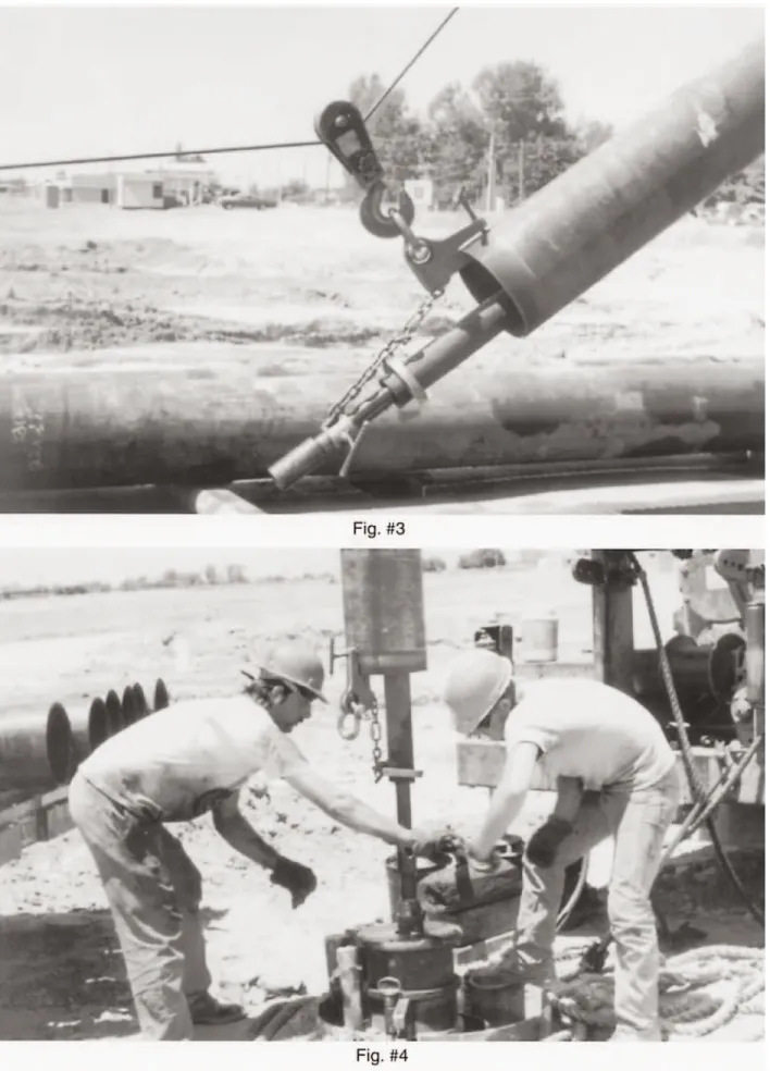
column/enclosing tube/shaft to be hoisted into place and assembled as demonstrated in Figure #3.
Non-standard lengths of column, enclosing tube and line shafting must be assembled at the top of the pump as previously outlined. Using an appropriate hoisting system, lift the shaft/tube/column assembly and position it above the suspended bowl. Slide the lower end of the shaft out of the enclosing tube about one foot. Refer to Figure #4 for lifting of this assembly.
3. Lower the shaft/tube/column assembly into position. A line shaft coupling is to already be in place on the pump shaft. Assure that the threaded shafts and coupling are clean and free of burrs. Lubricate threads with light oil. Thread the shafts into the coupling so that both shafts engage the coupling equally. The shafts should butt together solidly in the cen ter of the coupling. Threads should be exposed on both ends of the coupling. Assure that no foreign matter exists between the shaft ends. Such a condition will cause shaft misalignment and will result in vibra tion and accelerated bearing wear.
4. Assure that all enclosing tube threads and connector bearing threads are clean and free of burrs. Coat connector bearing threads with a sealant such as Loctite PST #567, Permatex No. 2 non-hardening gasket sealant prior to assembly. Silicone sealants are also permissi ble. This step is very important in preventing entry of the pressurized pumped media into the enclosing tube. Thread the enclosing tube onto the connector bearing and secure with chain wrenches.
5. Clean all coating or foreign materials from the column flange faces prior to assembly. Lower the shaft/tube/column assembly into position and coat the flange faces with sealant. Assure that the flange faces engage squarely and that all bolt holes align. Install bolts and nuts and tighten.
Install a spider if required. To determine if one is required, refer to page 9, under “Enclosed Line Shaft”.
6. Lift the column and bowl assembly slightly. Remove the pipe clamp from the bowl and lower the assembly into the well. Reinstall the pipe clamp on the upper end of the col umn directly below the upper flange. Lower the assembly until the pipe clamp supports the assembly on the foundation plate.
7. Repeat the above steps until complete. Continue to measure the shaft projection after assembly of each shaft/tube/-column section. Before installing the discharge head, pre-lubricate the connector bearings by pouring oil down the enclosing tube. Approximately
one pint of oil should be added for every 20 ft. of pump length.
8. Install column flange gasket (when used) to the upper column flange and secure to the discharge head being sure it is timed with the pipe tap hole of the discharge head.
9. Coat both sides of the copper gasket and the tension nut threads with sealant prior to installation. Install the bronze top tube ten sion nut gasket onto the top tube tension nut. 10. Install the top tube tension nut over the pro jecting line shaft and slide into position in the discharge head. Referring to Table #5 for thread rotation, thread it into the top enclos ing tube. The threads should engage the tube smoothly and allow the washer and nut to seat squarely in the counterbore of the dis charge head. Torque the top tube tension nut (refer to Table #2).
Oil Lubricated Enclosed Lineshaft with Threaded Column
Install column couplings the upper end of the column prior to lifting. This will provide a stop for pipe clamps during the hoisting process. 1. Using an appropriate hoisting system, lift the
pre-assembled bowl assembly and position it above the well. Lower the bowl assembly partially into the well and attach a pipe clamp (see Figure #1) to the upper most bowl direct ly under the bowl discharge flange. Lower the assembly, allowing it to be suspended on the foundation plate via the pipe clamp.
2. Before proceeding with assembly, lay out all line shaft, enclosing tube, spiders (if
required), column and connectors. Inspect
IMPORTANT
Line shaft threads are left hand rotation. Refer to Table #5 for enclosing tube thread rotation. Tighten shafts, enclosing tubes and couplings securely with pipe wrenches.
IMPORTANT
Measure the shaft projection. It should con-form to the shaft projection measurement recorded previously on the bowl assembly.
NOTE
Although standard column length is 5 or 10 feet, some non-standard lengths of col-umn, enclosing tube and shaft may be required to accomplish the specified over-all length of the pump. These non-standard lengths should be installed at the top of the column, directly under the discharge head.
and identify all items and arrange them in the order in which they will be assembled. Oversized diameter enclosing tube sections (if used) must be installed at the bottom of the assembly, directly above the pump dis charge bowl. When oversized tube sections are used, special stepped connector bearings are provided in order to adapt them to the remaining standard diameter enclosing tube sections.
Pre-assemble matching sets of shaft, enclos ing tube and column by sliding them inside each other and attaching connectors and cou plings. This will allow each set of
column/enclosing tube/shaft to be hoisted into place and assembled as demonstrated in Figure #3.
Non-standard lengths of column, enclosing tube and line shafting must be assembled at the top of the pump as previously outlined. Using an appropriate hoisting system, lift the shaft/tube/column assembly and position it above the suspended bowl. Slide the lower end of the shaft out of the enclosing tube about one foot.
3. Lower the shaft/tube/column assembly into position. A line shaft coupling is to already be in place on the pump shaft. Assure that the threaded shafts and coupling are clean and free of burrs. Lubricate threads with light oil. Thread the shafts into the coupling so that both shafts engage the coupling equally. The shafts should butt together solidly in the cen ter of the coupling. Threads should be
exposed on both ends of the coupling. Assure that no foreign matter exists between the shaft ends. Such a condition will cause shaft misalignment and will result in vibration and accelerated bearing wear.
4. Assure that all enclosing tube threads and connector bearing threads are clean and free of burrs. Coat connector bearing threads with a sealant such as Loctite PST #567, Permatex No. 2 non-hardening gasket sealant prior to assembly. Silicone sealants are also permissi ble. This step is very important in preventing entry of the pressurized pumped media into the enclosing tube. Thread the enclosing tube onto the connector bearing and secure with chain wrenches.
5. Lower the column and thread it into the bowl assembly until it solidly butts together with the bowl, tightening it firmly with pipe wrenches.
The line shaft and enclosing tube is to project out beyond the end of the installed column. Install a spider if required. To determine if one is required, refer to page 9, under “Enclosed Line Shaft”.
6. Lift the column and bowl assembly slightly. Remove the pipe clamp from the bowl and lower the assembly into the well. Reinstall the pipe clamp on the upper end of the col umn directly below the upper column threads. Lower the assembly until the pipe clamp sup ports the assembly on the foundation.
IMPORTANT
Line shaft threads are left hand rotation. Refer to Table #5 for enclosing tube thread rotation. Tighten shafts, enclosing tubes and couplings securely with pipe wrenches.
IMPORTANT
Assure that no burrs or foreign matter exists on the column coupling threads or on the column threads prior to assembly. All joints are to be coated with sealant prior to assem-bly. The column sections should butt together solidly and squarely in the middle of the column coupling. Secure each joint firmly with appropriate wrenches. ALL COLUMN THREADS ARE RIGHT HAND ROTATION.
IMPORTANT
Measure the shaft projection. It should con-form to the shaft projection measurement recorded previously on the bowl assembly.
7. Repeat the above steps until complete. Continue to measure the shaft projection after assembly of each shaft/tube/-column section. Before installing the discharge head, pre-lubricate the connector bearings by pouring oil down the enclosing tube. Approximately one pint of oil should be added for every 20 ft. of pump length.
8. If supplied with a SDC model discharge head, thread the top column directly into the threaded connection of the head and tighten with appropriate wrenches. If supplied with a LAD model discharge head, thread the top column adapter flange onto the top column and tighten with appropriate wrenches. Install column flange gasket and secure the discharge head to the column adapter flange. When attaching the column to the discharge head, make sure the flange is timed with the pipe tapped hole in the discharge head.
9. Install the bronze top tube tension nut washer onto the top tube tension nut. Coat both sides of the copper gasket and the tension nut threads with sealant prior to installation. Install the bronze top tube tension nut gasket onto the top tube tension nut.
10. Install the top tube tension nut over the pro jecting line shaft and slide into position in the discharge head. Referring to Table #5 for thread rotation, thread it into the top enclos ing tube. The threads should engage the tube smoothly and allow the washer and nut to seat squarely in the counterbore of the dis charge head. Torque the top tube tension nut (refer to the technical data page for correct torque values).
Driver Installation
VERTICAL HOLLOW SHAFT DRIVERS General
Hollow shaft drivers provide a hollow tube through the rotor. The pump shaft passes through the tube and attaches at the top of the driver. Turbine fire pump designs provide a shaft coupling above the packing box or tube tension nut. This allows the motor or gear to be set in place and the top section of shaft installed later, through the top of the driver.
Register fits on the bottom of the motor or gear base and on the top of the discharge head (motor pedestal) will facilitate approximate driver positioning. The fits are generally loose enough to accommodate the additional move-ment required for precision alignmove-ment. After precision alignment is achieved, the driver is permanently held in position by the clamping force of the mounting bolts. Doweling or pin-ning of the driver is not required, but may be implemented at the owner's option.
A. Before installation, remove the driver top cover. Remove the non-reverse ratchet. This will facilitate top shaft installation and rota tion check.
B. Using an appropriate hoisting system, lift the driver over the discharge head mounting sur face and carefully lower into position. Engage the driver base over the register fit of the mounting surface.
C. Bolt the driver down. If an electric motor is
NOTE
Standard shaft and column lengths are 5 or 10 feet. Non-standard lengths of shafts and column may be used to accomplish the required overall pump length. Non-standard shaft/column sections will always be assem-bled at the top of the pump, directly under the discharge head.
IMPORTANT
Read and understand the driver manufactur-er's manual before proceeding.
CAUTION
Care should be taken to avoid motor/shaft contact during this process as a bent top shaft could result.
used, now is the time to connect it to the elec trical source and to verify correct rotation. If a right angle gear is used proceed to step ‘D’.
With non-reverse ratchets removed or disabled, "bump" the motor for rotation. This is generally accomplished on three-phase motors by engag-ing and immediately disengagengag-ing the power switch. It is seldom necessary to engage the power source for more than one second to determine motor rotation.
Note the direction of motor rotation. If the motor rotates counter clockwise as viewed from the top, the rotation is correct and installation may proceed. If the motor rotates clockwise as viewed from the top, reverse any two of the three power leads and motor rotation will be reversed.
D. Install the pump's driver top shaft through the top of the motor or gear and tighten into the line shaft coupling. Make sure that the top shaft is centered in the tube.
E.Install the driver coupling and non-reverse ratchet. Install the gib key (supplied with the driver) into the driver/shaft keyway. The key should be a close slip fit in the keyways. It may be necessary to deburr or file the key to achieve the proper fit. Never drive or wedge the key into an overly tight keyway.
F. Install the top shaft adjusting nut. The adjust ing nut will be used to lift the shaft/impeller assembly in order to achieve proper impeller clearance. Refer to Table #6 for adjusting nut thread rotation.
G. Tighten the nut on the shaft until the
impellers are raised very slightly off the bowl bottoms. This will be evident when resistance to shaft rotation disappears as the impellers are lifted off the bottom.
H. With the impellers very slightly off the bot tom, add the additional nut turns required to achieve the specified clearance. Determine the correct impeller setting from the
Technical Data page found in the drawing section of this manual.
.
DANGER
Electrical motors must be installed and operated only by qualified, trained electri-cal technicians. Consult the motor manu-facturer or the motor manual to assure that all installation and safety procedures are fully understood and implemented. Always lock out all controls and or sup-plies and verify driver cannot be started before installing or servicing electrical apparatus.
CAUTION
Oil lubricated drivers and right angle gears are shipped dry and require an initial fill of the manufacturer's recommended lubricant prior to bump-start.
CAUTION
Line shaft threads are left hand rotation. Operation of the pump in a clockwise (as viewed from the top) direction will cause the line shaft couplings to unthread, caus-ing serious damage to the pump.
CAUTION
Assure that no burrs or foreign matter exists on the shaft threads.
NOTE
Before installation of the nut, the weight of the shaft/impeller assembly rests on the bottom of the pump bowls. This condition makes the shaft almost impossible to rotate until the nut is installed and the shaft/impellers are raised off the bottom of the bowls. In running position, the shaft, impellers and hydraulic down thrust are supported by the driver thrust bearing and the top shaft adjusting nut.
I. After impeller adjustment, place the adjusting nut lock screw through the nut and thread into the driver clutch coupling and secure. If the nut must be rotated to align with the clutch coupling hole, always move to the next high er adjustment position.
J. Replace the driver cover.
K. Refer to the driver manual to assure that all lubrication instructions have been followed completely.
L.Consult the driver manufacturer's manual to insure that all safety procedures are complete ly understood and implemented prior to oper ation.
SECTION 4 OPERATION
GeneralBecause variations may exist in both the equip-ment and in the particular installation of the a pump and driver, specific operating instructions are not within the scope of this manual. However, there are general rules and practices that apply to all pump installations and opera-tion.
Before starting the pump
1. Rotate the unit or assembly by hand to assure all on moving parts are free.
2. Install coupling guards around all exposed rotating parts. Guards are mandatory on dis charge head openings if the pump is equipped with an adjustable coupling.
3. Install packing.
4. Install bypass water line to packing box. 5. Observe all DANGER, WARNINGand
CAUTIONtags attached to this equipment. 6. Ensure water in sump is at the specified level
for adequate submergence.
7. If pump has a packed box, adjust the packing gland finger tight. Refer to Packing
Adjustment in the maintenance section to properly adjust packing.
If excessive vibration or noise occurs during operation, shut the pump down and review the Trouble Shooting section. If the problem can-not be corrected, consult an Fairbanks Morse representative.
Initial Startup and Test Procedure
Inspect the complete installation to ensure that the installation instructions of this manual, and the manuals of all the related equipment, have been followed and that the installation is com-plete.
NOTE
Extremely long pumps (deep settings) may require additional nut adjustment to accommodate line shaft stretch. Extra adjustment is not generally required for pumps less than 150 feet in length. For pumps over 150 feet long, consult the fac-tory for instructions.
IMPORTANT
Grease lubricated drivers are shipped pre-lubricated. Oil lubricated drivers and right angle gears driver are shipped dry and require an initial fill of the manufacturer's recommended lubricant prior to startup. See driver manufacturer's manual for lubrication specifications. Initial start-up lubricants are NOT supplied by the manu-facturer. Enclosed line shaft units will require installation of oiler prior to startup.
CAUTION
Before starting or operating the pump, read this entire manual, especially the fol-lowing instructions.
Ensure that the driver is properly serviced, and that the proper pump rotation is obtained. Rotate the pump shaft by hand. It should rotate freely on motor driven installations.
Ensure the discharge valve is closed.
Start the pump according to the following pro-cedure:
1. Start the driver according to the driver manu facturer's instructions.
2. Immediately after the pump has been started, slowly open the discharge valve, check lubri cation system, stuffing box lubrication and operation, and pump noise level. Continue to monitor these during the test procedure. 3. Check the driver and other necessary equip
ment for satisfactory operation following their manuals.
4. Check the foundation for integrity.
5. After the first shutdown, repeat the impeller adjustment. Running may have tightened up some of the shaft joints, changing the original setting.
Normal Operation
Monitor the following during running cycles: 1. Unit vibration or noise.
2. Driver lubrication levels and flow. 3. Packing box leakage.
Check the following before normal startup: 1. Driver lubrication levels and flow. 2. General condition of all equipment.
Shutdown
Fire pump stations are usually designed to have the pumps started automatically. Since this is a function of station design, the operators should be familiar with the systems operating parame-ters. The general procedure to shut down the pump is per NFPA#25 and as follows:
1. Disconnect the electrical power source or the diesel engine at the controller and lock in the off position.
2. If the pump is to be removed for repair, close the discharge valve.
Troubleshooting
If you have followed the installation and start up procedures outlined in this manual, your pump should provide reliable service and long life. However, if operating problems occur, sig-nificant time and expense can be saved if you use the following checklist to eliminate the most common causes of those problems.
Pump Symptoms
Insufficient Pressure or Flow 1. Wrong direction of rotation.
a. Reverse any two motor lead connec tions. Check driver 0 & M.
2. Impeller running clearance too great. a. Reset impeller clearance per 0 & M
manual.
3. Insufficient suction bell submergence. a. Raise wet well level.
4. Speed too low.
a. Check driver speed and voltage. 5. Bowl passage partially plugged.
a. Clean bowl passages.
6. Impeller passage partially blocked. a. Clean impeller passages. 7. Clogged suction.
a. Clean suction passages. 8. Low water level.
a. Raise wet well. 9. Air in liquid.
a. Increase submergence to prevent vortex ing.
10. Improper sump design. a. Change sump design.
WARNING
After removal of pump, ensure pump opening is adequately covered and secured.
IMPORTANT
The operator or persons working around the equipment should be familiar with locations of emergency start-up and shut-off points.
b. Increase submergence to prevent vortex ing.
11. Impeller damaged.
a. Check and repair or replace.
Loss of Suction Operation
1. Low water level.
a. Raise wet well level.
2. Insufficient suction bell submergence. a. Raise wet well level.
3. Wrong direction of rotation.
a. Reverse any two motor lead connec tions. Check driver 0 & M.
4. Air or gasses in liquid. a. Deareate liquid.
b. Increase submergence to prevent vortex ing.
Excessive Power Consumption
1. Improper impeller adjustment causing rub bing.
a. Readjust impeller clearance setting as outlined in this manual.
2. Speed too high.
a. Check driver speed and voltage. 3. Improper voltage to driver.
a. Check driver voltage.
b. Change power source or driver. 4. Misalignment.
a. Check engine to gear alignment. 5. Packing box gland too tight.
a. Readjust packing gland. 6. Shaft bent.
a. Replace shaft.
7. Specific gravity or viscosity of liquid pumped is too high.
a. Reduce pump capacity.
Vibration or Noise
1. Foundation bolts loose or defect in grouting. a. Tighten foundation plate bolts and/or
re-grout.
b. Tighten head to foundation plate bolts. 2. Worn pump bearings.
a. Replace pump bearings.
3. Pipe strain-improperly supported or improp erly aligned.
a. Check pipe supports and adjust or realign.
4. Shaft bent.
a. Replace shaft.
5. Insufficient suction bell submergence. a. Increase submergence.
6. Low water level.
a. Increase wet well level. 7. Air in liquid.
a. Increase submergence to prevent vortex ing.
8. Impeller passages clogged. a. Clean impeller passages. 9. Foreign object in pump.
a. Remove foreign object. b. Check for damage. 10. Bad driver bearing.
a. Replace driver bearing. 11. Improper sump design.
a. Change sump design. Increase submer gence to prevent vortexing.
Execessive Packing Box Leakage
1. Gland not properly tightened. a. Adjust packing gland. 2. Worn packing or sleeve.
a. Replace packing and/or sleeve. 3. Ends of packing not staggered.
a. Repack to stagger packing ends. 4. Bypass is plugged or restricted.
a. Clean by-pass line.
Over-Heating
1. Packing gland too tight. a. Adjust packing gland. 2. Shaft bent.
a. Replace shaft.
Driver / Controller Symptoms
The trouble or symptoms, their probable causes and suggest remedies contained in this trouble shooting guide will assist you in quickly deter-mining and correcting most problems should they occur.
It is not the intent of Aurora Pump to replace the recommendations of the motor manufactur-er in regard to opmanufactur-eration and maintenance of the
motor. Rather, this guide is offered as a supple-ment to such data.
Any specific questions or problems should be directed to the manufacturer of the motor. Be sure to supply relevant data from the motor nameplate when inquiring about service or maintenance.
Driver Does Not Start
1. Refer to motor or engine manufacturers’ O&M manual.
Driver Fails To Come Up To Speed
1. Refer to motor or engine manufacturers’ O&M manual.
Motor Runs Hot
1. Inadequate ventilation.
a. Assure adequate supply of fresh air. 1) Check air blast through motor by feeling air discharge at bottom of motor. 2. Overload.
a. Check for tight or locked shaft.
Motor Vibrates
1. Motor and pump mis-aligned. a. Re-align pump and motor.
b. Tighten foundation or pump bolting. 2. Worn bearings or bent shaft.
a. Disconnect pump from motor and run motor only.
(1) Repair as necessary.
3. Hydraulic disturbance in discharge piping. a. Check piping.
4. Unbalanced rotor assembly.
a. Refer to motor manufacturers’ O&M manual.
Driver Is Noisy
1. Refer to motor or engine manufacturers’ O&M manual.
Incorrect Rotation
1. Refer to motor or engine manufacturers’ O&M manual.
SECTION 5 MAINTENANCE
Preventive MaintenanceTo assure satisfactory operation of the pump, scheduled inspection and periodic maintenance are required. We suggest an inspection and maintenance log be kept and the inspector immediately report any problems.
This Aurora Pump model vertical turbine fire pump is supplied with either product lubricated or oil lubricated column and product lubricated bowl bearings only. The suction bell bearing is grease packed at the factory. It is not necessary to re-lubricate this bearing except when the pump is to be torn down for maintenance and the bowl assembly is to be disassembled.
A guide for preventive maintenance for normal applications is given below. Unusual applica-tions with abnormal heat, moisture, dust, etc., may require more frequent inspection and ser-vice.
Grease Recommendation DANGER
Electrical power must be disconnected and locked to prevent accidentally starting dur-ing mechanical systems check.
DANGER
Electrical trouble shooting must be per-formed by qualified electricians skilled in the use of electrical instruments.
The following lubricants are recommended for both potable and non-potable pumping systems:
Non-Potable System Potable Water System
Packing Adjustment
Packed box pumps should be checked during each weekly test and the glands should be read-justed if necessary. Initial adjustment is accom-plished by tightening the gland nuts finger tight.
Packing Replacement
Use only genuine Aurora Pump replacement packing. The replacement procedure should be as follows:
A. Stop the pump.
B. Unbolt and remove the gland.
C. Use a flexible packing tool* with a hook attachment for removal of the packing. *The packing tool can be purchased from the
factory or local supply house.
D. Clean the packing box and shaft sleeve. E. Inspect the shaft sleeve for wear or rough finish and replace the sleeve with a genuine Aurora Pump sleeve if necessary.
F. Install the new packing.
A. Refer to the technical data section for perti nent stuffing box and packing dimensions. B. Reinstall the gland and tighten the gland nuts
finger tight. After the pump has been started adjust the glands so that there is a steady stream, approximately 1/8" diameter, from the packing box.
Item Action Required
Seal Box Inspect during each weekly test for excessive leakage. Adjust or replace packing as required.
Driver Bearings Lubricate according to instructions given in the driver O&M.
Pump Alignment Check for changes annually. Correct as required.
Noise Level Check for changes during each weekly test. Correct as required.
Pump Vibration Check for changes during each weekly test. Correct as required.
Manufacturer Type
Generic N.L.G.I. #2 Lithium base multi-purpose grease with a mineral oil viscosity of 750-1050 SSU at 100˚F and 75-82 SSU at 210˚F Atlantic ARCO MP #2 Richfield Gulf Gulfcrown #2 Sinclair Litholine MP #2 Texaco Marfak #958 Manufacturer Type
Generic N.L.G.I. #2 meeting FDA Regulation 178.3570 and has USDA Type H-1 and FDA approvals for inciden tal food contact
Chevron FM Grade 2
Ideal FG #2
Keystone Nevastone HT/AW2
Lubriplate FGL-2
Mobile FM Grade 2
CAUTION
Excessive tightening of the glands may cause shaft sleeve damage.
DANGER
Lock out electrical power or diesel engine controller in the off position to prevent acci-dental starting and causing possible personal injury.
IMPORTANT
Stagger the packing end joints 180 degrees∞ and firmly seat each ring of packing as you install it.
Pump Disassembly
Major maintenance beyond lubrication, adjust-ment of impeller or wear ring clearance, and replacement or adjustment of the packing will require disassembly of the pump. The following are step-by-step instructions and are essentially the reverse of the installation procedure.
Driver Removal
Vertical Hollow Shaft (VHS) Driver
A. Stop the pump and lock out the power to the driver. Close the discharge valve. Disconnect the electrical cables from the driver.
Disconnect and remove gauges and all other auxiliary piping. (Stuffing box lubrication) B. Remove the driver cover and adjusting nut lockscrew. Lower the shaft until the impeller rests on the bowl seat. Remove the adjusting nut and gib key.
C. Disconnect the shaft coupling under the driv er and remove the top shaft. Remove the cap
screws holding driver to discharge head. D. Lift the driver from the head and set aside.
Discharge Head Removal
A. Remove and disassemble the pump head, the column, packing box and shafting according
to the following procedure which is essential ly the reverse of the installation procedure. B. Remove the packing gland bolts (8), glands
(9), water slinger (6) and packing (15).
C. Loosen and remove all the discharge piping flange bolts.
D. Remove the packing box bolts and remove the packing box from the head and shaft to a work area for inspection & cleaning. The packing box bearing (17A) is an interference fit in the packing box. The removal of this bearing will require the use of a mechanical press the bearing maybe removed by machin ing or other similar methods. Use care when removing bearings to not damage bores or hubs.
E. Lift entire unit with the lifting lugs and install a column clamp just below the upper column flange leaving room to remove the
flange bolting. Lower unit so that the column clamp rests on adequate supports.
F. Remove the bolts holding the column to the discharge head. Lift the discharge head off the unit and set aside.
Column Removal Flanged Column
A. Install eyebolts of sufficient size in the col umn flange holes and lift the unit and reposi tion the clamp below the next column flange. B. Use column and shaft clamps (or other
acceptable method) to safely support and lift this assembly.
C. Unbolt column flange and lift column
WARNING
Read this entire disassembly procedure and refer to the sectional drawings in this manual before starting.
DANGER
Check with proper electrical testing equip-ment to be certain all electrical power to the driver and accessories associated with the pump is disconnected.
CAUTION
Always use protective eyewear.
WARNING
Use a guide rope going from the sling joint, the head, attached to the discharge flange. This will keep the head from tipping over, possibly causing personal injury.
DANGER
Use a crane or hoist of adequate capacity to prevent serious personal injury.
enough to loosen the shaft coupling. When all components are loose, carefully lift this assembly from the pump unit. With soft skid boards under the column to protect the flange, slowly lower the column and shaft assembly
onto the floor and move to a convenient work area.
D. Repeat above steps A, B & C until all col umn and shaft sections have been removed from the unit.
E. Remove the bearing retainer assembly for inspection and cleaning.
F. Remove shaft section from column pipe. Remove couplings from shafts and inspect for wear or damage.
G. Inspect bearings and retainers for damage. H. If the top and intermediate drive shaft
sleeves (13 & 29) show wear or damage
remove the sleeve by heating it to 350˚F-400˚F to break the Loctite bond.
I. Refer to Pump Bowl Disassembly for detailed bowl disassembly procedures.
Threaded Column
A. Lift the unit and reposition the clamp below the next column coupling.
B. Use column and shaft clamps (or other acceptable method) to safely support and lift this assembly.
C. Unscrew the column coupling and lift col umn enough to loosen the shaft coupling. When all components are loose, carefully lift
this assembly from the pump unit. With soft skid boards under the column to protect the threads, slowly lower the column and shaft
assembly onto the floor and move to a conve nient work area.
D. Repeat above steps A, B, and C until all col umn and shaft sections have been removed from the unit.
E. Remove the bearing retainer assembly for inspection and cleaning.
F Remove shaft section from column pipe. Remove couplings from shafts and inspect for wear or damage.
G. Inspect bearings and retainers for damage. H. If the top and intermediate drive shaft
sleeves (13 & 29) show wear or damage remove the sleeve by heating it to 350˚F-400˚F to break the Loctite bond.
I. Refer to Pump Bowl Disassembly for detailed bowl disassembly procedures.
Pump Bowl Disassembly
For disassembly of the pump bowls, proceed in accordance with steps listed below. Select a clean area for work. Refer to assembly drawing and parts list for part identification.
Flanged Bowls
A. Place the bowl assembly in a horizontal position, blocked to prevent rolling.
B. Measure and record the axial end play of the shaft. This must be checked on reassembly of the bowls.
C. Remove the shaft coupling(31).
D. Remove the capscrews holding the top inter mediate bowl (55) and discharge case (54) or water lube adapter (54A) and remove from the pump shaft (32) and set aside for inspec tion.
D. For keyed impellers, skip to step ‘I’. E. Remove the impeller (38) and collet (39)
from the pump shaft according to the follow ing procedure:
IMPORTANT
Shaft threads are left-hand rotation.
IMPORTANT
Measure and record the position of the sleeves (13 & 29) on the shafts before removal. They must be put back in exactly the same place.
CAUTION
To prevent possible serious personal Injury always wear heat resistant gloves when han-dling heated parts.
IMPORTANT