DELTA 1
VIDEO DISPLAY TERMINAL REFERENCE MANUAL
Delta
Data
Systems
CorporationDELTA 1
VIDEO DISPLAY TERMINAL
REFERENCE MANUAL
DELTA 1
1.0 1.1 1.2 1.3 1.4 2.0 2.1 2.2 2.3 2.4 2.5 2.6 2.7 2.8 2.9 3.0 3.1 3.2 3.3 3.4 3.4.1 4.0 4.1 4.2 4.3 5.0 5.1 5.2 5.3 5.3.1 5.3.2 5.3.3 5.3.4 5.3.5 5.4 5.4.1 5.4.2 5.4.3 5.5 5.5.1
TABLE OF CONTENTS
Introduction Selective Blink Editing Package Remote Programming Cursor Controls
Systems Configuration Display Control Display Read-Only Memory Memory Control Refresh Memory Edit Control Serial I/O Control Parallel I/O Controller Keyboard
Modes of Operation Conversation Mode Format Mode Normal Mode Graphic Mode Light Pen Tracking
TV Compatibility Use with CCTV Equipment Raster Scan Sync Signal and Composite Video
5.5.2 5.5.3 5.6 5.6.1 5.6.2 5.6.3 5.6.4 5.7 5.7.1 5.7.2 5.7.3 5.7.4 5.7.5 5.7.6 5.7.7 5.7.8 5.7.9 5.7.10 5.7.11 5.8 5.9 6.0 6.0.1 6.0.2 6.1 6.1.2 6.1.3 6.1.4 6.1.4.1 6.1.4.2 6.1.5 6.2 6.2.1 6.2.2 6.3 6.3.1 6.3.2 6.3.3 6.3.4 6.3.5 7.0 7.1
Enter Addressed Line Enter Addressed position Edit Commands Insert Command Insert Line Command Delete Command Delete Line Command Display Controls Set Blink Clear Blink Cursor Left Cursor Right Cursor Up Cursor Down.
Return New Line Home Backspace
Tab Party Line Signals Interrupt System
Serial Communications Communication Interface Synchronous Interface
Serial Controller - IBM Compatible
ASCII Communication Control Characters Addressing Sequences Sequence/Response Dialogue Transmit Data Commands Enter Data Commands Error Control Teletype Compatibility Serial Controller Echoplex Mode Normal Mode Serial Interface (RS-232B)
Grounds Data Signals Control Signals Additional Control Signals Electrical Signal Characteristics
Parallel Interface Controller
FIGURES
DELTA 1 USASCII CODE
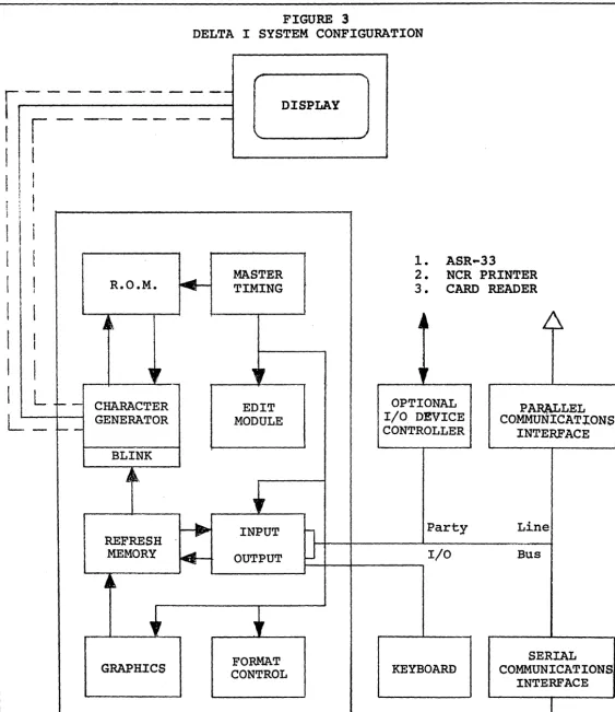
3.0 DELTA 1 System Configuration
5.1 Input/Output Party Line Schematic
5.2 Party Line Data Input Timingl
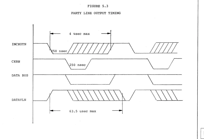
5.3 Party Line Output Ti~in~
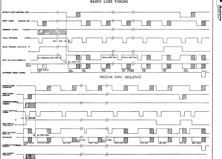
5.4 Party Line Timing
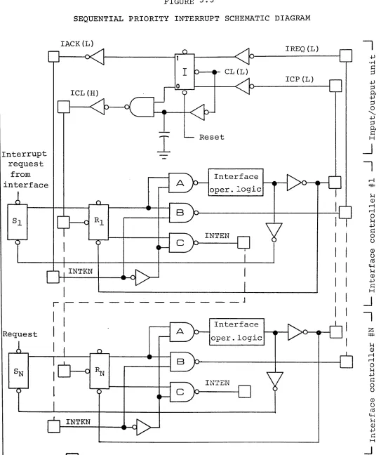
5.5 Sequential Priority Interrupt Schematic Diagram
6.1
6.2
7.1
7.2
8.0
9.0
5.1
7.1
Sequence/Response Diagram for Transmit Data Commands from the Computer Sequence/Response Diagram for Enter Data Commands from the Computer
Sequence/Response Diagram for Transmit Data Commands from the Computer via a Parallel Interface Sequence/Response Diagram for Enter Data Commands from the Computer via a Parallel Interface
Bits and DELTA 1 Control Codes
Keyboard
TABLES
Party Line I/O Connector
1.0 INTRODUCTION
The DELTA 1 VIDEO DISPLAY TERMINAL is a complete stand alone computer terminal for rapid entry, transmission,
and retrieval of digital information. It consists of
a controller, an alpha-numeric keyboard and a CRT
dis-play. A standard T.V. monitor is used for display of
an EIA-TV compatible signal. This makes possible the
operation of many T.V. monitors in a room or building to display information to many users.
The DELTA 1 has a capacity of 960 characters, 40 on
each of 24 lines. A graphics mode provides display of
graphic information on a 128 by 64 matrix. Complete
capability for editing, formatting and transmitting data is included to provide data manipulation hereto-fore unavailable with a terminal in this price class.
Communications with the DELTA 1 is provided through an
EIA compatible serial communications interface. The
serial interface provides ASCII communications
capa-bility to make the ~ELTA 1 compatible with the Model
2701 communications controller of the IBM software. A parallel interface is also available with DTL
electrical compatibility. Data is transferred through
the parallel interface using a REQUEST-ACKNOWLEDGE control sequence providing compatibility with computer input/output.
The most complete set of editing and format controls are provided to simplify operator manipulation and
preparation of data. The character insert and delete
keys open or close a space on a line and the line
insert or delete keys open or close a line space. The
format control permits entering and protecting fixed information while the operator enters variable
infor-mation. Transmission and clearing of the variable
information provides a high level of efficiency of operation.
The selective blink feature permits any characters at selected positions to blink to call the operator's attention to the data.
Complete cursor control from the keyboard as well as the computer is provided by cursor controls to position
the cursor anywhere on the screen. Variable
options offered for the DELTA 1 include a light pen, hard copy devices for printing what is on the screen, closed circuit T.V. equipment for use in conjunction with the DELTA 1, and various interfaces for communi-cation and direct connection to other computers.
A. Options also include a 96 character set where
the 32 additional characters are either:
1. Lower case.
2. Line drawing characters.
3. ASCII control code graphic symbols.
(The use of any of these options requires that the blink capability be deleted.)
1.1 SELECTIVE BLINK
The SELECTIVE BLINK feature permits the computer to call attention to important information displayed on
the screen. Such information blinks on and off at
approximately a once per second rate. The operator's
eye is captured by the blinking and he can take appro-priate action to acknowledge receipt of such information.
Blink will cause any field of characters to be in the
BLINK condition. When BLINK is established for a given
character position, any displayable characters stored in that position will blink on and off on the screen. Clearing the position to a space or changing the
char-acter will not stop the blink function. To stop a field
from blinking, the appropriate command must be entered for each position for which the blink function should
be terminated. In this way, each position may be
sep-arately and independently programmed to blink or to stop blinking as required.
BLINK is independent of the format function and will be affected by whether a given position is FIXED or
VARIABLE data in the FORMAT MODE. Edit commands will
change the location of the blink field as well as data.
1.2 EDITING PACKAGE
A. Insert
The Insert Command causes a character space to be opened up at the position of the Cursor and all characters at that position and to the right are
moved over one place. The last character on the
line is discarded. The Cursor remains in its same
position and repeated operation of this key will
open up a multi-position space. The data to be
inserted can then be typed directly in without
affectinq subsequent lin~of data. This is used
to add a letter or a number in the middle of an-other group of numbers or letters.
B. Insert Line
This command takes the entire line of data on which the Curosr is located and moves i t and all lower
lines down one line. The bottom line of data is
discarded. This opens up an entire line of data
for insertion into the body of the text.
C. Delete
This command causes the character at the position of the Cursor to be replaced by the one immediately on its right and all characters to the right of the Cursor position to be moved to the left one
posi-tion. A space is brought into the last position
on the line. It is used to remove a word or
char-acter from a line without replacing i t with
some-thing else. It differs from the normal typing
operation where any new characters typed over an old one will simply repla,ce the old character with the new one.
D. Delete Line
This command causes all characters on the same line as the Cursor to be replaced by all the characters
on the next lower line. All lines below that are
moved up one line and spaces are brought into the bottom line from a text without replacing i t with a different line.
E. Roll and Crawl
One of the important capabilities of the DELTA 1 Terminal through the edit functions is the ability to ROLL data up and down by the use of the
dele-tion-Qr insertion command. New lines of data can
can appear on the screen of the terminal. The same thing can be true for a single row of charac-ters, CRAWLING from left to right or right to left. In each case the appropriate characters or lines to be entered can be displayed and moved up, down, left or right.
1.3 REMOTE PROGRAMMING
The DELTA 1 display is capable of responding to a vari-ety of commands to provide for remote operation of the
various function controls. These include all of the
format controls, the erase controls, and the transmit
control. In addition, the remote computer can cause the
Cursor to be set at any fixed position on the screen by providing an absolute address to the terminal.
1.4 CURSOR CONTROLS
An extensive set of Cursor Controls is provided on the
DELTA 1. These are designed with two points of view;
For operator convenience, and to provide complete flex-ibility to the computer programmer.
At the keyboard, there are 7 Cursor Commands~ These
include UP: DOWN, LEFT, and RIGHT. Also provided is the
HOME command which:mD-Ves the Cursor to the first posi-tion of the first line, the RETURN command which moves the Cursor to the first position of the following line, and the BACKSPACE command which moves the Cursor back one position.
All of the above Cursor Commands are programmable from the computer which also has the capability for absolute' positioning the Cursor any where on the screen with the
POSITION CURSOR COMMAND. The Cursor command, given with
a line and position number, will automatically move to
the position addressed. This provides the ultimate in
2.0 SYSTEMS CONFIGURATION
The DELTA 1 display station consists of a number of mod-ular components described in the following paragraphs:
2.1 DISPLAY CONTROL
The function of display control is to generate master timing, integrate the refresh memory, generate the char-acter font, and convert the digital charchar-acter informa-tion into a signal capable of being recognized by a
standard T.V. monitor. It also contains an EIA RS170
compatible sync generator which produces composite sync
and composite video signals. Optionally available is
a source of control signals necessary to permit the Display Controller to be the source of synchronization for any closed circuit T.V. facility.
2.2 DISPLAY
The technique used for generation and display of data
employs a scanned raster approach. The display is a
atandard CRT T.V. monitor mounted in
a
desk top housing.The 12" screen will display 960 characters in 24 rows
of 40 characters each. Mounted on the side of the
dis-play station are three control knobs, for brightness,
contrast, and horizontal hold. At the users option,
other displays may be attached to the same controller providing the opportunity to monitor the contents of
the screen in several different locations. These
moni-tors can be additional DELTA 12" display screens, or large screen remote monitors can be used.
2.3 READ-ONLY MEMORY
The read-only memory is a permanent storage device. It
is programmed to contain a pattern of one's and zero's which represent the shape of each of the standard 64
characters which can be displayed on the screen. Since
each character is made up of seven rows of five dots each, the memory is broken up into 64 x 7 words of five bits each.
2.4 MEMORY CONTROL
Memory control serves the purpose of addressing the refresh memory and controlling the source and
scan in which the display is active, memory access is controlled by a real time clock counter which defines character position along the line and character line on
the page. During this time the data is transferred
from core memory to the Display Control.
If new characters are to be entered into the refresh memory or if some other form of an edit is pending, during the period of time in which the raster is re-tracing., the memory address is the cursor address. Data is either extracted from the memory or entered in-to the memory during the retrace time,. as defined by Edit Control.
2.5 REFRESH MEMORY
The refresh memory is a high speed, random access
mag-netic core storage. This unit contains 1024 eight-bit
words. In the DELTA 1, six bits are used for storage
of which of the 64 characters in the set is to be
dis-plqyed. The other two bits are used to store blink
and format information. In a 96 character-set display
or in a color terminal, one or the other of the remain-ing two bits may be used for other information.
2.6 EDIT CONTROL
The function of Edit Control is to perform all editing operations for the data received from either the com-puter or the keyboard, and for sending all data to the computer.
The basic edit functions include control of transmission to and from a computer, clearing all or sections of
the display, entering data into the display, controlling the cursor on the display, or manipulating data via the insert, insert line, delete, or delete line commands.
2.7 SERIAL I/O CONTROL
The function of the Serial I/O Controller is to permit the display system to communicate with a computer via
a communications line. The Serial I/O Controller
transmits and receives serial ASCII Coded data via a
telephone company supplied modem and converts i t to edit, transmit, or control commands for the display.
2.8 PARALLEL I/O CONTROLLER
The function of the Parallel I/O Controller is to permit direct communications between the display system and
other I/O devices. Such devices include small general
purpose computers, paper tape readers or punches, card
readers or punches, magnetic~ tape controllers, line
printers, and the keyboard.
The parallel I/O Controller contains a party line data bus permitting the display controller and other peripheral
devices to share common information. To insure proper
direction of information flowing into or out of the data
lines, an interrupt structure is used. Thus, any device
requiring service will make a request which is stored in the Parallel I/O Controller, and when the Controller completes the processing associated with some other I/O device control is transferred to the requesting
peri-pheral. During the time that this peripheral is using
the data bus, all other requests are stored and only the peripheral presently using the I/O data bus can con-trol the flow of data to or from the display concon-troller.
2.9 KEYBOARD
The keyboard, as shown in figure 9, contains a
stan-dard typewriter keyboard, a display edit keyboard, and
a display control keyboard all in one package. The
standard typewriter keyboard permits entry of 26 charac-ters, ten numbers, and 24 special symbols.
The edit keyboard permits relative motion control of the cursor (up, down, left, and right), homes the cursor, permits the establishment of formats and blink fields, and permits the operator to enter or delete characters or lines.
The control keyboard permits the operator to request transmissions, to clear a message, display, line, to re-set the display"to select the mode of operation, and the mode of display, and permits a limited number of special controls which will cause actions on external
3.0 MODES OF OPERATION
There are three modes of operation for display of
alpha-numeric information. These are 1) conversation mode,
2) format mode, and 3) normal mode.
3.1 CONVERSATION MODE
The Conversation Mode is provided to facilitate conver-sational dialogue between the computer and the DELTA 1
terminal. The purpose is to simplify operator actions
in communicating with the computer and to permit the past conversation with the computer to be left displayed on the screen.
After Activation of the Conversation Mode Key, the Mode
Light will go on. The address of the cursor is stored
in a register and the operator types his inquiry to the
computer. The last character of the message will be an
End Of Message (EOM) symbol. The terminal transmits
all information between the cursor locations stored ln
the register and the End Of Message symbol. The
com-puter begins its reply on the next line leaving displayed
the inquiry to the computer. When the computer has
com-pleted transmission of its message, i t sends a Return and
returns control to the terminal. The terminal again stores
the address of the cursor in the address register and the operator can type in the next inquiry.
In the Conversation Mode i t is not necessary to constantly reposition the cursor to the beginning of a message in
order to transmit. Furthermore, the entire dialogue
between computer and operator remains displayed on the screen instead of being cleared after each communication.
The Conversation Mode is an important factor in the man-machine interface problem by simplifying communications
with the computer. It, therefore, simplifies operator
intervention and training.
3.2 FORMAT MODE
The Format Mode is designed to simplify man-machine
inter-action. It is used when a pre-established format is
An example of a format would be:
NAME: ADDRESS:
CITY: STATE: ZIP:
S. S.
#:
EMPLOYER:
The computer would transmit data in the Normal Mode to establish such a format. Now, operating in the Format Mode, the operator would be unable to erase the format
information. Operation of the tab control would move the cursor to the start of the first variable data field. The operator would then type (TAB) Richard M. Nixon
(TAB) 1600 Pennsylvania, Ave (TAB) WASHINGTON (TAB) D.C. (TAB) 21111 (TAB) 333-333-3333 (TAB) U.S. GOVERN-MENT (END OF MESSAGE).
The screen would then look like this:
NAME: RICHARD M. NIXON
ADDRESS: 1600 PENNSYLVANIA AVE
CITY: WASHINGTON STATE: D.C.
S. S. #: 333-333-3333 EMPLOYER: U.S. GOVERNMENT
ZIP: 21111
Now the operator is ready to transmit the variable data to the computer. Since the computer established the format in the first place, i t knows what the format information is. The transmit button is pushed and the terminal sends only the variable data. Now, the clear screen command is activated. This will clear the vari-able data and bring the screen back to just the format information, ready for a new entry.
When a delete or insert character editing function is operated in the Format Mode, i t only operates on the field from the cursor to the end of the line or the end of the variable data field, whichever shall occur first.
3.3 NORMAL MODE
The Normal Mode is the usual operating condition of the DELTA I terminal. It provides unrestricted use of the editing functions. Clear commands will operate on all character positions and all data specified will be trans-mitted in a send operation.
3.4 GRAPHIC MODE
screen is divided up into 8192 spots on the face of the
screen. Each eight bit character in the refresh memory
of the terminal describes an on-off condition for any one of a corresponding eight spots on the face of the
screen. The computer can then transmit data to the
mem-ory to provide a pattern of l i t and unlit spots that will draw lines, circles, and curves and generate
char-acters on the face of the screen. In this way graphic
data may be displayed and annotated using the DELTA 1.
No relationship exists between the positioning of the alpha-numeric data on the screen and the graphic data.
3.4.1 LIGHT PEN TRACKING (OPTIONAL)
Light Pen Tracking permits use of the light pen to draw
lines and curves on the face of the screen. When the
light pen tracking control has been operated, the move-ment of the pen across the face of the screen will cause
dots along the path of the pen to be turned on. This
4.0 T.V. COMPATIBILITY
The DELTA 1 Terminal is a T.V. compatible display. This means the signal generated to drive the display portion of the terminal is compatible with the television signal generated in any closed circuit television system. This opens up a broad avenue of applications for the DELTA 1
Terminal. Because of T.V. COMPATIBILITY, we are able to make use of a standard solid state 12" T.V. set in our terminal at an accompanying savings to the user. This savings is in the form 6f initial cost as well as maintainability because the operation of the circuits within the display are identical to those of part of a
standard commercial television set.
4.1 USE WITH CCTV EQUIPMENT
The T.V. compatible signal drives a standard 525 line T.V. monitor or modified T.V. set. The display asso-ciated with each keyboard can be monitored remotely through a closed circuit television system. A single television distribution amplifier can be used to drive several remote monitors in different locations.
A standard commercially available Video Tape Recorder may be used to record the data being displayed for later retrieval and display. The output of a closed circuit television camera can be combined with the signal from the DELTA 1 terminal to superimpose computer generated information onto a T.V. signal for display or recording. This is useful in many applications where existing
closed circuit television systems can be combined with the output data generated by a computer. Graphic data such as pictures from slides or art work can be scanned by a T.V. camera and annotated by the signal from DELTA 1 terminal.
4.2 RASTER SCAN
Characters are created on the screen in the TV raster mode by blanking and unblankinq of the TV beam as i t
moves laterally across the screen. The beam moves across the screen 525 times to create a normal TV picture. Suc-cessive sweeps skip every other line creating two fields of scan of 262 and 263 lines equally spaced up and down the screen. This is known as an interlace. In the
The display characters are formed in the middle 212 T.V. lines which made up of seven lines per character and two lines between rows on each of 24 rows of characters. The cursor is written on the 8th line of each character row and the 9th line is always used as a separation to to row below.
It takes approximately 52 microseconds for the beam to sweep from one side of the screen to the other and approx-imately 12 microseconds for i t to return back to the left
hand side. During the 52 microsecond period as i t sweeps
the screen, the beam is turned on and off to generate one
line of the character. However, the first 5 microseconds
of the sweep are not used in order to assure a placement of the characters in the center of the screen and reduce maintenance problems from drift of the characters to the left or right of the visible area of the screen.
4.3 SYNC SIGNAL AND COMPOSITE VIDEO
The output signal from the Delta 1 generator to the dis-play station and to remote monitors is a standard EIA Video signal as per specification RS 170 of the
Electri-cal Industries Association. This specification provides
the exact timing and characteristics of the synchroni-zation signal for the TV receiver and the composite video signal.
The sync signal must have a pulse at the beginning of each line of video data to cause the beam to return from the right hand side of the screen to the left hand side. When the proper number of these pulse signals have been generated at 60 microsecond intervals, a horizontal
synchronization sequence is generated. These provide the
triggering necessary for the TV receiver to cause return of the beam from the bottom of the screen on the right
to the top of the screen on the left. The receiver is now
ready to receive a new vertical sync pulse and video data for the next field of display.
Standard synchronization signals are available as outputs from the generator to be used to trigger T.V. cameras and other closed circuit television equipment used in
conjunction with the DELTA 1 terminal. Sync signal is
mixed with the digital data to provide a composite video
signal. This is the type of signal normally received
system. The compatibility with EIA standard RS 170 assures operation with closed circuit or broadcast TV equipment.
When operating
in
conjunction with TV equipment, itis
5.0 INPUT-OUTPUT TRANSFER
All data transferred to and from the DELTA I passes
through the party line input/output bus. This consists
~f eight bi-directional data lines and a series of
con-trol lines. These control lines provide for transfer
of data through the data register. Data is transferred
to and from the memory via the data register.
A priority input/output structure is provided through the party line I/O to permit various devices to gain exclusive access.
The single input/output port provided by the party line I/O is used by the serial communications interface, the parallel communications interface as well as other I/O
devices. All data exchanged with the external world is
passed to the memory through the party line I/O.
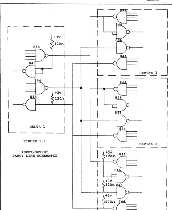
5.1 PARTY LINE I/O BUS
The DELTA 1 controller employs a "Party Line" I/O bus to communicate with peripheral equipment.
The party line at the last device must be terminated with a resistor whose value is the characteristic
impedence of the signal line. This is done to minimize
reflections. Since the data lines are bilateral, i.e.
they can be driven from either end, a termination is
required at each end. The control lines, which are
unilateral, are required to be terminated only at the
receiving end of the line. Figure 5.1 shows the circuit
schematics of both types lines. Signal lines should be
twisted pairs. Peripheral design should try to minimize
the length of the line. While the controller can
operate at long distances an effort should be make to keep the party line cable under 12 feet long.
5.2 COMMANDS
All commands described in the following paragraphs
may be initiated from a remote source. To initiate
them the controller expects the fiist input word to be the code for the command and the COMEN signal to be true
during the transfer. If the command is a XMIT the
The DATAVL signal will be turned off from the time the command data transfer is initiated until the command
has been completed. At the conclusion of the command
the controller will place an ACK code (for receive
data commands) or an STX character (for send data commands)
into the data register. Data is then transferred from
the party line to the peripheral controller or other peripheral device under external control.
5.3 TRANSMIT COMMANDS
The transmit commands provide for transmission of data
to a computer. Information to the right of a new line
symbol on any transmitted line will not be transmitted. This conserves transmission time.
When the display is in the Format mode, only those characters located in "Variable" field positions are transmitted to the I/O device.
5.3.1 TRANSMIT MESSAGE (0100000)
This command causes the contents of the display from the present location of the cursor to an end of message symbol to be transmitted to some I/O device at a rate
compatible with that device. At the end of the command,
the cursor is located at the character position following the end of message symbol.
In the Conversational mode the cursor is backed up
automatically to the first character after the last end of message indicator before executing the transmission sequence.
5.3.2 TRANSMIT DISPLAY COMMAND (0110000)
This command causes the cursor to reset to the origin location on the display and transmit the contents of every location on the display to the input/output
device. At the conclusion of the transmission, the
5.3.3 TRANSMIT LINE COMMAND (0100001)
This command transmits to the requesting I/O device all information from the present location of the cursor to
the end of the line. At the conclusion of the command,
the cursor is located at the first location on the next line.
5.3.4 TRANSMIT X ADDRESS COUNTER (01000010)
This command causes the contents of the X address
counter to be transmitted. The X address is the position
of the cursor on the line. It varies from zero to 39.
5.3.5. TRANSMIT! ADDRESS COUNTER (0100011)
This command causes the contents of the Y address
counter to be transmitted. The Y address is the line
address of the cursor.
5.4 CLEAR COMMANDS
5.4.1 CLEAR MESSAGE COMMAND (1100001)
This command will reset to a space character code the contents of all display locations from the present position of the cursor to but not including the end
of message (EOM) symbol on the screen. At the
conclusion of this command the cursor will be located at the character position following the EOM symbol.
5.4.2 CLEAR DISPLAY COMMAND (1100000)
The execution of this command causes the cursor to
reset to the origin position and causes the replacement with a space character code of all character positions
on the display screen. At the conclusion of the command
the cursor is reset to the origin position.
5.4.3. CLEAR LINE COMMAND (1100010)
This command causes the replacement with a space
character code all display positions from the present
position of the cursor to the end of a line. At the
5.5 ENTER COMMANDS
There are three enter commands acknowledged by the
terminal to permi~ display of data from the computer.
5.5.1 ENTER (1000000)
'This command causes data received to be displayed
beginning at the, present cursor position. If more
than forty characters:are entered on a line of the display, an automatic over-flow to the next line of the display
will occur. No return command need be entered when
i t is desired to display more than forty characters
before a return symbol occurs. If 50 characters are
transmitted followed by a return, th~ first forty will
occur on a line and the next ten will occur on the
following line. Subsequent data will begin at the
start of the third line.
5.5,.2' ENTER ADDRESSED LINE (1010000)
Data will be entered on a line whose number is specified by the first character after the STX in the message. The X address counter will be reset to zero so that
the message begins at the first position of the addressed line. ,If a Y address is, entered which is greater than 23, the cursor will be positioned in an imaginery
place below the screen. Line addresses greater than 32
will cause entry on a line specified by the line address modula 32.
5.5.3 ENTER ADDRESSED POSITION (1010001)
This command provides for entering of data on the
screen beginning in
a
specified position of a line.The first character after the STX command specifies
the position on the line. Data following the X
position address will be displayed beginning at the position specified and continue across the line and on
subsequent lines. The Y address counter is unaffected
by this instruction.
NOTE: On all enter commands, the terminal will treat
the first'line as if i t were immediately after the
last line of the display. For example, a return
command given on the bottom line of the display will cause the cursor to go to the home position.
5.6 EDIT COMMANDS
This command causes a space character code to be
inserted onto a display line at the location of the cursor and causes all remaining characters to the right of this location to be moved one character to the right. The character in the right most position is discarded. At the conclusion of this command the cursor is returned to the location of the space character code to permit the operator or computer to enter a new character.
In the format mode the space character is inserted and all characters moved right one place until the end of the variable field.
5.6.2 INSERT LINE COMMAND (1110001)
This command causes a line of space code characters
to be inserted on the line where the cursor is presently located and causes all subsequent lines below this line to be pushed down one line. The last line on the display is deleted from memory. At the conclusion of this command the cursor is located at the start of the new inserted line. In the format mode this command is invalid.
5.6.3 DELETE COMMAND (1110010)
This command causes the character located at the preset location of the cursor to be deleted from the display and all subsequent characters to the right of the cursor to be moved one position to the left. At the conclusion of this command the cursor is returned to the location at which the delete occurred. A space coded character is inserted as the last character on this line. In the format mode only variable data may be deleted and all characters in the variable field up to the cursor are moved to the left.
5.6.4 DELETE LINE COMMAND (1110011)
This command causes the erasure of all characters on the line signified by the cursor. All lines below this line are pushed up one line. At the conclusion of this command the cursor is located at the starting position on the line just deleted. This command is invalid in format mode.
5.7 DISPLAY CONTROLS
5.7.1 SET BLINK (0010010)
This command causes the present cursor location to be designated as a blink position so data will blink any
time a character is located at this position. At the
conclusion of the command the cursor is incremented one character position.
5.7.2 CLEAR BLINK (0010011)
This command resets the blink control for the present
cursor location. At the conclusion of this command
the cursor is incremented one character location.
5.7.3 CURSOR LEFT (0011101)
This causes the cursor to move one position to the left.
Data is unaffected. If the cursor was on the leftmost
position on the line before the key was operated, the cursor will go to the last position on that line. Data is unaffected.
5.7.4 CURSOR RIGHT (0011100)
This causes the cursor to move one position to the right.
Data is unaffected. If the cursor was on the rightmost
position of the line before the key was operated, the cursor will go to the first position of the same line. Data is unaffected.
5.7.5 CURSOR UP (0010110)
Moves the cursor to the same position on the preceeding
line. Data is unaffected.
5.7.6 CURSOR DOWN (0010111)
Moves the cursor to the same position on the next
line down. Data is unaffected. If the cursor was
on the bottom line, i t will go to the first line on the screen.
5.7.7 RETURN (0001010)
5.7.8 ~ LINE (1111111)
The character is entered on the screen. This character
defines the end of a line during transmit commands, and the end of a field if in the format mode.
5.7.9 HOME (0011011)
Moves cursor to the first position'of the first line
on the screen. Data is unaffected.
5.7.10 BACKSPACE (0001000)
Moves cursor back one position. Data is unaffected.
if cursor is in the first position of the line, i t will go to the last position of the same line.
5.7.11 TAB (0001001)
The Tab Command is used when the display is in the Format Mode to facilitate the location of Variable
Fields. Execution of the Tab Command causes the cursor
to move to the first position of the next variable data field.
5.8 PARTY LINE SIGNALS
Data Bus - IDIBON to IDIB7N - eight bidirectional lines
that transmit data between peripheral devices and the
DELTA I controller. IDIB7N is the most significant
bit, IDIBIN is the least significant bit and IDIBON is the parity bit (ignored by the controller unless
longitudinal pary check (LRCC) is utilized).
Control Bus - ten lines that transmit or receive control
signals between the DELTA 1 and I/O devices. The
signals are described as follows:
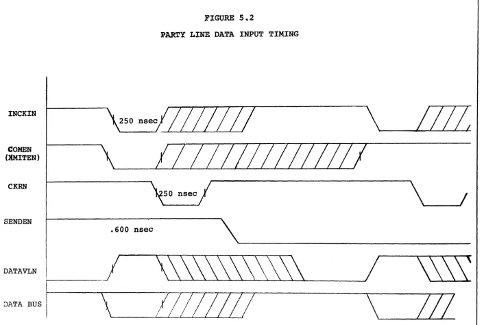
INCKIN
INDKOTN
Input clock. ,This signal is 'received by the Delta I and defines the period of time that new data is available to be
entered into the controller. This signal
must be true until a CKRN is received at the peripheral.
Output clock. This signal is received,by
the Delta I and causes the controller to place a word on the Data Bus.
Information to be sent to the peripheral
is valid for that period of time from
CKRN SENDEN COMEN ~~ITEN DATAVLN INTRN VRCERN
Clock response. This signal is sent by
the DELTA I and defines to a peripheral
when input data has been received and
when output data is available. This
signal goes true 250 nanoseconds after the INCKIN or INCKOTN goes true and lasts for 250 nanoseconds.
Send/Receive. This signal is transmitted
by the DELTA I and defines to a peripheral whether the next data transfer is to be
from or to controller. The signal
will change state about 500 nanoseconds after the INCKIN or INCKOTN signal
becomes true if a change is expected.
Command Enable. The DELTA I expects
that the first word of every transmission
sequence be a command. The command
enable signal must be true from just prior to the first INCKIN signal at least until a CKRN is received by the
peripheral. It may stay true until the
next INCKIN or INCKOTN.
Transmit enable. This signal has
characteristics similar to COMEN and is required in addition if the command is a transmit.
Data Available. This signal is transmitted
by the DELTA I and defines to a peripheral when the data bus is available for the
next INCKIN or INCKOTN. This signal
goes false as either clock goes true and remains false until the controller has completed the operation associated with the data transfer.
Interrupt Reset. This signal is transmitted
by the DELTA I and defines to a peripheral when in time the message has been completed. This signal occurs at the leading edge
of the last CKRN of a message transfer and is 250 nanoseconds long.
Parity Error. This signal is received
by the DELTA I controller at any time during a message transfer and causes the controller to retransmit a message
(transmit screen only) at the completion of the message or respond with a NAK
for received messages. (This signal is
RESETN
IREQ
lACK
ICL
ICP
Reset. This signal is transmitted by
the DELTA 1 controller to peripherals when an operator depresses the RESET Key
on the Keyboard. It may also be received
from the peripheral. This signal causes
the controller to reset all control flags to an initial state.
Interrupt request. This signal is
generated by the interface controller and when true indicates that a request for service is being made.
Interrupt Acknowledge. This signal is
generated by the Input/Output unit in response to an IREQ and indicates that the I/O unit is ready to respond to the interface controller.
Interrupt clock. This signal is
gener-ated by the I/O unit and is used to clock the request FF's in the interface
controller. When the lACK is true,
this signal is not present.
Interrupt complete. This signal is
generated by the interface controller
when its operation is complete. It is
used to reset all request FF's in all
interface controllers. The serviced
unit must reset its request storage
FF at the same time. This pulse must
be
>
1 < 2 times the ICL time.Function Bus - Three lines that transmit pulses to a
peripheral to initiate some action. All these lines
are related to keys on the keyboard. (While three are
available up to 10 can optionally be added.)
XMITSWN
PRINTSWN
READSWN
Transmit Switch. This signal is
transmitted to a peripheral when an
operator depresses the XMIT key. The
signal produced is true for 2 micro-second.
Print Switch. Same as above only
initiated by operation of Print" Key.
Read Switch. Same as above only
initiated by operation of the Read Key.
Table 5.1 defines the connector pin assignment for connect-ing external peripherals or their controllers to the
DELTA 1. Figures 5-1, 5-2, 5-3 describe the timing of
5.9 INTERRUPT SYSTEM
The interface controllers employ a unit sequential inter-rupt system which permits several interface devices to
communicate with the display. To accomplish this, each
interface controller must provide a signal to all sub-sequent controllers (INTERN) to indicate that i t is not
using the DELTA 1. It can only provide this signal if
no other higher priority device has previously generated
i t (INTKN). Figure 5.5 shows a schematic of the
interrupt structure.
Each interface controller is prohibited from generating party line clocks until i t has received priority.
As shown in Figure 5.5 and INTEN signal is the INTKN of the next controller.
OPERATION OF INTERRUPT SYSTEM
The interrupt system shown schematically in Figure 5.5,
operates as follows. When a request is determined by
the interface controller, the request storage FF (SI ... SN)
is set. On the next trailing edge of the interrupt
clock (ICL) , the request FF is set for each device where
the request storage FF is set. Since the lACK and each
INTEN is high at this time, 'the IREQ is brought low. The
interrupt FF (I) is set causing lACK to go low and the
ICL to be removed from the bus. When INTKEN of the
first controller goes low indicating that priority is available, the common input of gates A and C are enabled. If Rl is set only gate A will have an output which
transfers priority to the next controller in the chain.
When the interface controller finishes its operation, i t generates an ICP which resets all request FF's (even those in other controllers) and its own request storage
FF. Since all request FF's are reset, there will be no
IREQ. The interrupt FF will then be reset, by the CL
during ICP, allowing the ICL to return to the bus and to set any request FF where there is a corresponding request
storage FF set. Thus, multiple requests will be serviced
6.0 SERIAL COMMUNICATIONS
Communications between a peripheral and the display
con-troller is always half duplex (except echoplex). For
serial communications this takes the form of either a
two-wire or four-wire system. For parallel
communica-tions i t takes the form of eight-wire communication plus a number of control signals.
An unpolled system is one in which operator requests for transmission to or from a computer are initiated upon his action.
For DELTA 1 displays a polled system permits the use of a single communication line to address a large number
of display controllers. The polled system is under the
control of the data processor and requires that the data processor elicit communications traffic from the display controller by means of a polling message which identifies the polling command and specifies the address of a dis-play controller which i t is asking, "Are there any messages available for -transmission?"
Because of the nature of the display command, two seven-bit words can specify the controller address (this
stimulates an IBM 2848 Display Controller and a 2260
Display Station). The total number of display controllers
accessible via this mode is in excess of 16,000.
A polled system allows the display controller to non-simultaneously transrnit and receive data to and from the
processor. If the control computer employs a full
du-plex communication channel, the communications from multi-display terminals to the computer permits trans-mitting data or polling messages to one station while receiving information from another even though at the display controller stations themselves, only half duplex operation is permitted.
6.0.1 COMMUNICA'TION INTERFACE
The Model 202C Modem permits asynchronous information to be transferred on the dial-up networks at rates up to 1,800 baud, and the Model 2020 modem permits asynchron-ous communication on the private line network up 1,800
baud. The Model 103A permits communication on either of
these networks at rates up to 150 baud.
The display controller also has available an option to remove the modem interface for providing serial communi-cation over a direct connection.
6.0.2 SYNCHRONOUS INTERFACE
The display controller also permits operation of a serial interface using synchronous modems permitting
trans-mission speeds of up to 9,600 baud using privat~ line
connections.
For synchronous communicacions at 2,400 baud, the Bell
Model 20lA Modem can be used. This modem can be used
in either a two-wire or four-wire system on either the dial-up or private line networks.
When a synchronous Modem is used in a polling environ-ment, the message must also contain a synchronization code which is the ASCII SYNC command repeated four times prior to the message normally required with the use of an asynchronous modem.
6.1 SERIAL CONTROLLER - IBM COMPATIBLE
The DELTA 1 terminal with this controller operates with the same communications dialogue and features as the
IBM 2265 Display with a (2845) Controller. This means
-that the IBM Display may be replaced on a plug to plug
compatible basis with the DELTA 1 terminal. To provide
this compatibility, the terminal is capable of respond-ing to a four-character pollrespond-ing sequence that is identical
to that which the IBM terminal expects. This sequence
consists of a communications command character (EOT or SOH Command), two address characters which the terminal is capable of recognizing and decoding for operation on a shared line, and the fourth character is a command. These commands are the communications commands and are
listed in section 5. Th~y provide for transmission of
If the transmit button has been depressed and the unit is in the transmit condition when the terminal is
requested to transmit, i t will respond with a start of text symbol (STX) and the message followed by and ETX
and an LRC code. The unit will respond with an EOT
character if the XMIT key has not been pressed indicating there is nothing to be transmitted.
When the unit transmits its message, the computer will respond either with an ACK (indicating the message was received without error) or an NAK (indicating the
mes-sage was received with errors). If the NAK is received,
the terminal will retransmit the entire message (XMIT
screen only). If the ACK is received, the terminal will
send an EOT character and unlock the keyboard.
6.1.2 ASCII COMMUNICATION CONTROL CHARACTERS
To establish and maintain an orderly flow of traffic over communication lines, particularly in multidrop applications (where more than one device is attached directly to the lines), a method of controlling line
traffic is necessary. Line traffic between the computers
and the remote display system is controlled by the use of six of the ASCII communication control characters. These six codes, used singly or in sequences, perform all the control functions necessary to establish and maintain an orderly flow of traffic between the channel and I/O devices attached to the communication lines.
The definition of each of these six ASCII characters is
given below. The code structure for each is given in
Figure 6.1
A. STX (Start Of Text) - A communication control
characters that is to be treated as an entity. This entity will usually be terminated by ETX.
B. ETX (End Of Text) - A communication control
character used to terminate a sequence of char-acters started with STX and transmitted as an entity.
C. ACK (Acknowledge) - A communication control
character transmitted by a receiver as an affirmative response to a sender.
D. NAK (Negative Acknowledge) - A communication
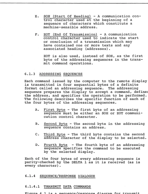
E. SOH (Start Of Heading) - A communication con-trol character used at the beginning of a sequence of characters which constitute a machine-sensible address.
F. EOT (End Of Transmission) - A communication
control character used to indicate the start or conclusion of a transmission which may have contained one or more texts and any associated heading (addresses).
EOT is also used, instead of SOH, as the first byte of the addressing sequences in the trans-mit command operations.
6.1.3 ADDRESSING SEQUENCES
Each command issued by the computer to the remote display is transmitted in four sequential bytes of a definite
format called an addressing sequence. The addressing
sequence prepares the display to accept a command, defines the address, and specifies the operation to be performed. The following describes the specific function of each of the four bytes of the addressing sequences.
A. First Byte - The first byte of an addressing
sequence must be either an SOH or EOT communi-cation control character.
B. Second Byte - The second byte in the addressing
sequence contains an address.
C. Third Byte - The third byte contains the second
address character of the display to be selected.
D. Fourth Byte - The fourth byte of an addressing
sequence specifies the command to be executed by the selected display.
Each of the four bytes of every addressing sequence is parity-checked by the DELTA 1 as i t is received (as is every character) •
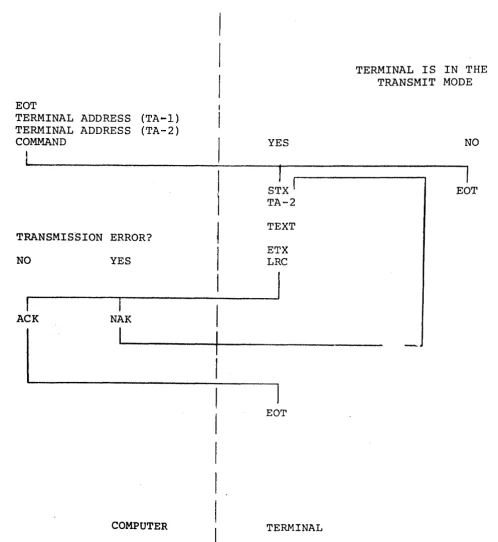
6.1.4 SEQUENCE/RESPONSE DIALOGUE
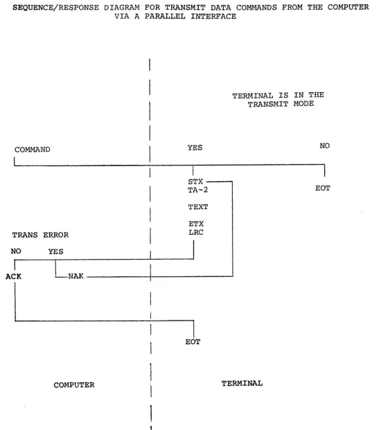
6.1.4.1 TRANSMIT DATA COMMANDS
Figure 6.1 is a sequence/response diagram for transmit
[image:33.620.35.535.65.721.2]a polling environment.
An EOT (or SOH) command will cause the terminal to treat the next two characters (TAl and TA2) as a terminal
address. These two characters will be coded and.checked
and if the proper address sequence is received, the fourth character received will be decoded as a command
to the terminal. This four character sequence is
pre-sent for all communications commands. The fourth
character could be any of the several transmit commands.
The terminal will respond dependent upon whether the transmit button has been pressed putting the machine in
the transmit mode. If i t has not, the terminal will
send an EOT character back to the computer indicating
the fact that the terminal has no data to transmit. If
the operator has pressed the transmit button, then the terminal will transmit a STX command (indicating the start of text), TA2 (the second of the two terminal addresses that were transmitted to i t by the computer in the fourth character command sequence), and the text
of the message that the terminal has to send. This
will be followed by an ETX (indicating the end of text) and an LRC (longitudinal redundancy check character) for parity checking by the computer.
The terminal remains in the transmit mode until the
response is received from the computer. If an error
was detected in transmission, the computer will send back an NAK which will cause the terminal to send STX
and begin the transmission of the text again. If no
ACK command and the terminal will respond with an EOT which will then unlatch both the computer and the
ter-minal from the communications. The on line light on the
terminal will be turned off and the machine will return to its previous mode.
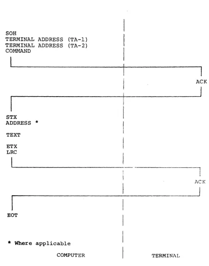
6.l.4.2ENTER DATA COMMANDS
Figure 6.2 is a sequence response diagram for Enter Data
Commands from the computer. The first character
communi-cations sequence will be either an SOH or EaT. The
terminal will see a two character terminal address which i t will decode to determine if i t is being addressed. If so, i t will decode the fourth character, the command
character. Upon receipt of an Enter Data Command and
detection of the correct address, the terminal will send
to the computer an ACK character. The computer will
transmit an STX character wh~ch would be used in those
or character position on the line followed by the text
to be displayed. An ETX command follows the text and
then an LRC. The terminal will respond with an ACK
(acnkowledge) indicating receipt of the message and the computer should respond to that with an EOT which will remove the keyboard and the terminal from the
Enter Data condition. If an error was detected by the
controller i t will respond with an NAK and the computer may (via software) retransmit or terminate.
6.1.5 ERROR CONTROL
Vertical Parity
As each character is received from the ~~dem i t is checked
for even parity. If a parity error is detected an error
flag is set and the character replaced by a CAN ( , )
character. As each character is sent to the modem an
even parity is generated.
Lon~itudinal Parity
An accumulator is used to keep account of all input and output data from the first character after an STX to an
ETX. This longitudinal accumulator is compared with the
first received character after an ETX (LRCC) and any
difference sets an error flag. During data transmission
the contents of the accumulator is transmitted as the first character after an ETX.
Error Retransmission
If the error flag is set during receipt of data the con-troller will respond with an NAK character after the
message is complete. The computer may be programmed to
cause retransmission upon detection of the NAK.
If the computer responds to the receipt of a message
with an NAK the controller causes the message to be trans~
mitted. (This is only valid if the transmit command is
6.2 TELETYPE COMPATIBILITY SERIAL CONTROLLER
The DELTA 1 terminal with this controller operates with
the same communications dialogue as a TTY. It can·
operate with either of two options -- Normal or
Echo-plex. It is designed to communicate with a remote
computer via a 103 serias Dataphone using either a
pri-vate line or the dial-up network. It may also be
connected to an acoustic coupler. The communications
are full duplex at 110 baud. (Up to 300 baud
option-ally available.)
6.2.1 ECHOPLEX MODE
In this mode the communications line is the only source
of data to be entered on the CRT. As each character is
typed on the keyboard i t is transmitted to the computer. The computer returns either the same character or an
error character (CAN, if a transmission error is detected) and displays it. The display advances the cursor one
position. If a vertical parity error is detected on
receipt of a word the CAN character is also displayed.
For TTY compatible communications initiation of commands from a remote source is not permitted.
6.2.2 NORMAL MODE
While the controller operates with a full duplex modem in "this mode data cannot be sent and received
simul-taneously. Received data is displayed (except control
characters) as i t is received. The operator may
create a display and then after editing i t transmit i t
as a block to the remote computer. This action is
initiated by the operator depression of the XMIT key.
If the operator has selected the Conversational mode the transmit command is a XMIT MESSAGE and the infor-mation transmitted is that inforinfor-mation from the previous EOM symbol to the latest EOM symbol (typed by the
operator after creating the display).
If the operator has not selected Conversational mode the transmit command is a XMIT SCREEN and all
informa-tion on the screen is transmitted (if also
in
a formatFor all transmissions the transmitted data is bracketed by an STX character and an ETX character.
For all receptions of data the detection of a parity error (even parity) cause a CAN symbol ( ' ) to replace the normal character.
6.3 SERIAL INTERFACE (RS-232B)
6.3.1 GROUNDS
Circuit AA -- Protective Ground
This conductor shall be electrically bonded to the
ter-minal frame. It may be further connected to external
grounds as required by applicable regulations.
Circuit AB --Signal Ground
This conductor establishes the common ground reference potential for all interchange circuits except circuit
AA (Protective Ground). In the data communication
equipment this circuit shall be brought to one point, and i t shall be possible to connect this point to cir-cuit AA by means of a wire strap.
This wire strap can be connected or removed at the installation, as may be required to meet applicable regulations or to minimize the introduction of noise into electronic circuitry.
6.3.2 DATA SIGNALS
Circuit BA -- Transmitted Data
Direction: From Terminal
Signals on this circuit are generated by the terminal and are connected to the transmitting signal converter for transmission to remote data processing equipment.
Ther terminal equipment holds Circuit BA in marking con-dition during any time interval between characters or words, or at such other times when no signals are to be
transmitted. .
Circuit BB --Received Data
Direction: To Terminal Computer
Signals on this circuit are generated by the receiving signal converter in response to data signals received from remote equipment.
In half-duplex service, the receiving data set shall hold marking condition on Circuit CA (Request to Send
in the OFF condition. Alternatively, in half-duplex
service, the Received Data circuit may be used to moni-tor transmitted signals (e.g., for local copy).
A data set equipped for Transmit-Only service shall hold Circuit BB in the marking condition at all times.
The marking or spacing signal condition shall be held for the total duration of each signal element.
6.3.3 CONTROL SIGNALS
Circuit CA -- Request to Send
Direction: From Terminal
Signals on this circuit are generated by the terminal equipment to condition the local data set to transmit. For example, if the data set contains a modulator, the carrier signal shall be transmitted during the ON condi-tion of Circuit CA.
The ON condition is maintained whenever the terminal equipment has information ready for transmission or
being transmitted. The signal converter shall transmit
all data on Circuit BA (Transmitted Data), while the ON condition is maintained on Circuit CA, Circuit CB
(Clear to Send), and Circuit CC (Data Set Ready) .
In half-duplex service, the OFF condition shall hold the data set in the receive-data condition, and the ON
condi-tion shall hold the data set in the transmit-data condicondi-tion. The above conditions shall be established without regard to signals on Circuits BA (Transmitted Data) and BB
(Received Data) .
Circuit CB -- Clear to Send
Direction: To Terminal
Signals on this circuit are generated by the transmitting data set to indicate that i t is prepared to transmit data. The ON condition is a response to the ON condition on
Circuit CA (Request to Send), delayed as may be appropri-ate to the data communication equipment for establishing a communication channel to a remote data processing
ter-minal. When Circuit CA is turned OFF, Circuit CB shall
be also turned OFF.
In Receive-Only service, the data set shall hold Circuit CB OFF at all times.
In Transmit-Only or Full-Duplex service, if the data com-munication equipment is arranged to be in transmit condi-tion at.all times, then Circuit CB shall be held in the ON condition at all times.
Circuit CC -- Data Set Ready
Direction: To Terminal
Signals on this circuit are generated by the local data set to indicate that i t is ready to operate.
The OFF condition shall be used to indicate either:
A. Any abnormal or test condition which disables
or impairs any normal function associated with the class of service being furnished.
B. That the communication channel is switched to
an alternate means of communication (e.g., al-ternate voice telephone).
C. That the local data set is not connected to a
communication channel (i.e., the data set is "on hook") .
The ON condition shall appear at all other times.
This circuit shall be used only to indicate the status
of the local data set. The ON condition shall not be