DESING & MODELING OF SCR BASED CONTROLLER FOR SPEED CONTROL
OF SINGLE PHASE INDUCTION MOTOR
1*
Sharad Chandra Rajpoot
1
Assistant professor (EE)
2
Assistant professor (EE) L.C.I.T., Bilaspur, Chhattisgarh, India
ARTICLE INFO ABSTRACT
This concept of restriction on the power supplied to
power control allows us to efficiently use the available power for various applications. There are two types of AC power control: ON
control. In on
AC supply is switched off for some interval.
connect and disconnect the load to the AC power supply. In phase method,
the AC supply for a specific period of both the half cycles. Firing angle control based AC power control is designed here which is a type of phase angle control. The circuit regulates the AC power supplied to any load like an elec
Copyright©2017, Sharad Chandra Rajpoot and Prashant Singh Rajpoot
License, which permits unrestricted use, distribution, and reproduction in any medium, provided the original work is properly cited.
INTRODUCTION
Induction motor has replaced DC drives in many applications due to its rugged construction, cost effectiveness. Its application varies from domestic such as washing machine, pumps, refrigerators, etc. To industrial applications such as industrial robots, electric vehicles, and elevators and so on. To obtain energy efficiency instead of running machine at a constant speed, speed control method is used. The conventional speed control methods suffer from various disadvantages like mechanical wear and tear, frequent maintenance requirement, less efficient and bulky. Therefore the use of power electronic devices and controll
role. It improving the above factors and also help them in soft starting. To achieve this simple and compact power electronic controller circuit called AC voltage controller is connected between the input ac supply and the load (single pha induction motor). Ac voltage controllers are semiconductor based circuits which convert fixed alternating voltage to variable alternating voltage without the change in frequency (IJIREEICE).
*Corresponding author:Sharad Chandra Rajpoot,
Assistant professor (EE) G.E.C. Jagdalpur, Bastar, Chhattisgarh, India.
ISSN: 0975-833X
Article History: Received 03rd June, 2017
Received in revised form 26th July, 2017
Accepted 04th August, 2017
Published online 29th September, 2017
Citation: Sharad Chandra Rajpoot and Prashant Singh Rajpoot
induction motor”, International Journal of Current Research
Available online at http://www.journal
Key words:
SCR, Induction motor, AC power supply, A.C. power control, ON-OFF control, Phase Angle Control,
Pulse Skipping Modulation Control.
RESEARCH ARTICLE
DESING & MODELING OF SCR BASED CONTROLLER FOR SPEED CONTROL
OF SINGLE PHASE INDUCTION MOTOR
Sharad Chandra Rajpoot and
2Prashant Singh Rajpoot
Assistant professor (EE) G.E.C. Jagdalpur, Bastar, Chhattisgarh, India
Assistant professor (EE) L.C.I.T., Bilaspur, Chhattisgarh, India
ABSTRACT
This concept of restriction on the power supplied to a device is known as AC power control. AC power control allows us to efficiently use the available power for various applications. There are two types of AC power control: ON-OFF control or pulse skipping modulation control and phase angle control. In on-off control, the load is connected to the AC supply for short interval of time and the AC supply is switched off for some interval. A fast switching device like a thyristor is used to connect and disconnect the load to the AC power supply. In phase method,
the AC supply for a specific period of both the half cycles. Firing angle control based AC power control is designed here which is a type of phase angle control. The circuit regulates the AC power supplied to any load like an electric bulb, motor, amplifier etc.
Sharad Chandra Rajpoot and Prashant Singh Rajpoot. This is an open access article distributed under the Creative Commons Att use, distribution, and reproduction in any medium, provided the original work is properly cited.
Induction motor has replaced DC drives in many applications due to its rugged construction, cost effectiveness. Its application varies from domestic such as washing machine, pumps, refrigerators, etc. To industrial applications such as industrial robots, electric vehicles, and elevators and so on. To obtain energy efficiency instead of running machine at a ed, speed control method is used. The conventional speed control methods suffer from various disadvantages like mechanical wear and tear, frequent maintenance requirement, less efficient and bulky. Therefore the use of power electronic devices and controllers play a vital role. It improving the above factors and also help them in soft starting. To achieve this simple and compact power electronic controller circuit called AC voltage controller is connected between the input ac supply and the load (single phase induction motor). Ac voltage controllers are semiconductor based circuits which convert fixed alternating voltage to ithout the change in frequency
Sharad Chandra Rajpoot,
professor (EE) G.E.C. Jagdalpur, Bastar, Chhattisgarh,
Some of the main applications for ac voltage controllers are for domestic and industrial heating, Transformer tap changing, lightening control, speed control of single phase and three phase ac motor drives. Earlier, the devices used for these applications were auto transformer, magnetic amplifiers, saturable reactors etc. But these devices are now replaced by thyristors and Triac based ac voltage regulators because of their high efficiency, flexibility in control
less control (Oluwasogo, 2014)
are phase-controlled devices, thyristors and Triac are line commutated and as such no complex commutation circuitry is required in these controllers. The purpose of an AC voltage controller, or AC regulator, is to vary the
the load at a constant frequency. For regulating the power flow in ac voltage controllers, control strategies are of two types:
Phase control
On-and-off control
SINGLE PHASE INDUCTION MOTOR:
Induction motor is variable speed electrom
which convert the A.C. input to mechanical output. It works on the principle of faraday’s electromagnetic induction. phase power system is widely used as compares to three phase
International Journal of Current Research
Vol. 9, Issue, 09, pp.57064-57070, September, 2017
Sharad Chandra Rajpoot and Prashant Singh Rajpoot. 2017. “Desing & modeling of scr based controller for speed control of single phase
International Journal of Current Research, 9, (09), 57064-57070.
Available online at http://www.journalcra.com
DESING & MODELING OF SCR BASED CONTROLLER FOR SPEED CONTROL
Prashant Singh Rajpoot
G.E.C. Jagdalpur, Bastar, Chhattisgarh, India
Assistant professor (EE) L.C.I.T., Bilaspur, Chhattisgarh, India
a device is known as AC power control. AC power control allows us to efficiently use the available power for various applications. There are two OFF control or pulse skipping modulation control and phase angle off control, the load is connected to the AC supply for short interval of time and the A fast switching device like a thyristor is used to connect and disconnect the load to the AC power supply. In phase method, the load is connected to the AC supply for a specific period of both the half cycles. Firing angle control based AC power control is designed here which is a type of phase angle control. The circuit regulates the AC power
is an open access article distributed under the Creative Commons Attribution use, distribution, and reproduction in any medium, provided the original work is properly cited.
Some of the main applications for ac voltage controllers are for domestic and industrial heating, Transformer tap changing, lightening control, speed control of single phase and three motor drives. Earlier, the devices used for these applications were auto transformer, magnetic amplifiers, saturable reactors etc. But these devices are now replaced by thyristors and Triac based ac voltage regulators because of xibility in control, compact size and ) Since the ac voltage controllers controlled devices, thyristors and Triac are line commutated and as such no complex commutation circuitry is required in these controllers. The purpose of an AC voltage controller, or AC regulator, is to vary the RMS voltage across the load at a constant frequency. For regulating the power flow in ac voltage controllers, control strategies are of two types:
SINGLE PHASE INDUCTION MOTOR:
Induction motor is variable speed electromagnetic device which convert the A.C. input to mechanical output. It works on the principle of faraday’s electromagnetic induction. Single phase power system is widely used as compares to three phase
INTERNATIONAL JOURNAL OF CURRENT RESEARCH
system for domestic purpose, commercial purpose and to s extent in industrial purpose. As the single phase system is more economical and the power requirement in most of the houses, shops, offices are small, which can be easily met by single phase system. The single phase motors are simple in construction, cheap in cost, reliable and easy to repair and maintain (IJIREEICE).
CONSTRUCTION OF SINGLE PHASE INDUCTION MOTOR
Like any other electrical motor induction motor also have two main parts namely rotor and stator.
STATOR OF SINGLE PHASE INDUCTION MOTOR
The stator of single phase induction motor has laminated stamping to reduce eddy current losses on its periphery. The slots are provided on its stamping to carry stator or main winding. In order to reduce the hysteresis losses, stampi made up of silicon steel (Oluwasogo, 2014
winding is given a single phase AC supply, the magnetic field is produced and the motor rotates at a speed slightly less than the synchronous speed Ns which is given by
NS = 120 f /P
Where, f = supply voltage frequency, P = no. Of poles of the motor. The construction of the sator of asychronous motor is similar to that of three phase induction motor except there are two dissimilarity in the winding part of the single phase induction motor. Firstly the single phase inductio
mostly provided with concentric coils. As the number of turns per coil can be easily adjusted with the help of concentric coils, the mmf distribution is almost sinusoidal. Except for shaded pole motor, the asychronous motor has two stator
namely the main winding and the auxiliary winding. These two windings are placed in space quadrature with respect to each other.
ROTOR OF SINGLE PHASE INDUCTION MOTOR
The construction of the rotor of the single phase induction motor is similar to the squirrel cage three phase induction motor. The rotor is cylindrical in shape and has slots all over its periphery. The slots are not made parallel to each other but are bit skewed as the skewing prevents magnetic locking of stator and the rotor teeth and makes the working of induction motor more smooth and quieter i.e less noise. The squirrel cage rotor consist of aluminum, brass or copper bars. These aluminum or copper bars are called rotor conductors and are placed in the slots on the periphery of the rotor
Thr rotor conductors are permanently shorted by the copper or aluminum rings calles the end rings. In order to provide mechanical strength these rotor conductors are braced to the end ring and hence form a complete closed circuit resembing like a cage and hence got its name as squirrel cage induction motor (Oluwasogo, 2014) As the bars are permanently shorted by the end rings, the rotor electrical resistance is very small and it is not possible to exernal resistance as the bars are permanently shorted. The abscence of slip ring and brushes make the construction of single phase induction motor very simple and robust.
WORKING
When single phase AC supply is given to the stator winding of single phase induction motor, the alternating current starts
57065 Sharad Chandra Rajpoot and Prashant Singh Rajpoot,
system for domestic purpose, commercial purpose and to some extent in industrial purpose. As the single phase system is more economical and the power requirement in most of the houses, shops, offices are small, which can be easily met by single phase system. The single phase motors are simple in and easy to repair and
OF SINGLE PHASE INDUCTION
Like any other electrical motor induction motor also have two
OF SINGLE PHASE INDUCTION MOTOR
of single phase induction motor has laminated stamping to reduce eddy current losses on its periphery. The slots are provided on its stamping to carry stator or main winding. In order to reduce the hysteresis losses, stamping are , 2014) When the stator winding is given a single phase AC supply, the magnetic field is produced and the motor rotates at a speed slightly less than
= no. Of poles of the motor. The construction of the sator of asychronous motor is similar to that of three phase induction motor except there are two dissimilarity in the winding part of the single phase Firstly the single phase induction motor are mostly provided with concentric coils. As the number of turns per coil can be easily adjusted with the help of concentric coils, Except for shaded pole motor, the asychronous motor has two stator windings namely the main winding and the auxiliary winding. These two windings are placed in space quadrature with respect to each
OF SINGLE PHASE INDUCTION MOTOR
The construction of the rotor of the single phase induction o the squirrel cage three phase induction motor. The rotor is cylindrical in shape and has slots all over its periphery. The slots are not made parallel to each other but are bit skewed as the skewing prevents magnetic locking of and makes the working of induction motor more smooth and quieter i.e less noise. The squirrel cage rotor consist of aluminum, brass or copper bars. These aluminum or copper bars are called rotor conductors and are he rotor (IJIREEICE) Thr rotor conductors are permanently shorted by the copper or aluminum rings calles the end rings. In order to provide mechanical strength these rotor conductors are braced to the end ring and hence form a complete closed circuit resembing s squirrel cage induction As the bars are permanently shorted by the end rings, the rotor electrical resistance is very small and it is not possible to exernal resistance as the bars are abscence of slip ring and brushes make the construction of single phase induction motor very
When single phase AC supply is given to the stator winding of single phase induction motor, the alternating current starts
flowing through the stator or main winding. This alternating current produces an alternating flux called main flux. This main flux also links with the rotor conductors and hence cut the rotor conductors. According to the faraday’s law of electromagnetic induction, emf gets induced in the rotor. As the rotor circuit is closed one so, the current starts flowing in the rotor. This current is called the rotor current. This rotor current produces its own flux called rotor flux. Now there are two fluxes one is main flux and another is called rotor flux. These two fluxes produce the desired torque which is required by the motor to rotate.
CAPACITOR START CAPACITOR RUN INDUCTION MOTOR
The working principle and construction of Capacitor start inductor motors and capacitor start capacitor run induction motors are almost the same. We already know that single phase induction motor is not self starting because the magnetic field produced is not rotating type. In order to produce rotating magnetic field there must be some phase difference. In case of split phase
resistance for creating phase difference but here we use capacitor for this purpose. We are familiar with this fact that the current flowing through the capacitor leads the voltage. So, in capacitor start inductor motor
run induction motor we are using two winding, the main winding and the starting wind
connect a capacitor so the current flowing in the capacitor i.e
Ist leads the applied voltage by some angle, φ
winding is inductive in nature so, the current flowing in running winding lags behind applied voltag
Now there occur large phase angle differences between these two currents which produce an resultant current, I and this will produce a rotating magnetic field. Since the torque produced by these motors depends upon the phase angle differ which is almost 90°. So, these motors produce very high starting torque. In case of capacitor start induction motor, the centrifugal switch is provided so as to disconnect the starting winding when the motor attains a speed up to 75 to 80% of the synchronous speed but in case of
induction motor there is no centrifugal switch so, the capacitor remains in the circuit and helps to improve the factor and the running conditions of single phase induction motor.
METHODOLOGY
[image:2.595.308.558.595.777.2]CIRCUIT DIAGRAM:
Fig. No. 1 Circuit diagram
Sharad Chandra Rajpoot and Prashant Singh Rajpoot, Desing & modeling of scr based controller for speed control of single phase induction motor
flowing through the stator or main winding. This alternating current produces an alternating flux called main flux. This main flux also links with the rotor conductors and hence cut the rotor conductors. According to the faraday’s law of duction, emf gets induced in the rotor. As the rotor circuit is closed one so, the current starts flowing in the rotor. This current is called the rotor current. This rotor current produces its own flux called rotor flux. Now there are in flux and another is called rotor flux. These two fluxes produce the desired torque which is required
T CAPACITOR RUN INDUCTION
The working principle and construction of Capacitor motors and capacitor start capacitor run induction motors are almost the same. We already know that uction motor is not self starting because the magnetic field produced is not rotating type. In order to produce rotating magnetic field there must be some phase difference. In case of split phase induction motor we use resistance for creating phase difference but here we use capacitor for this purpose. We are familiar with this fact that flowing through the capacitor leads the voltage. So, capacitor start inductor motor and capacitor start capacitor we are using two winding, the main winding and the starting winding. With starting winding we connect a capacitor so the current flowing in the capacitor i.e
leads the applied voltage by some angle, φst. The running
winding is inductive in nature so, the current flowing in
running winding lags behind applied voltage by an angle, φm.
Now there occur large phase angle differences between these two currents which produce an resultant current, I and this will produce a rotating magnetic field. Since the torque produced by these motors depends upon the phase angle difference, which is almost 90°. So, these motors produce very high capacitor start induction motor, the centrifugal switch is provided so as to disconnect the starting winding when the motor attains a speed up to 75 to 80% of the chronous speed but in case of capacitor start capacitors run there is no centrifugal switch so, the capacitor remains in the circuit and helps to improve the power and the running conditions of single phase induction
Fig. No. 1 Circuit diagram
BLOCK DIAGRAM
Fig. No. 2 block diagram
The device is aimed at substituting commonly used TRIAC phase angle control drives. This circuit is capable of supplying single-phase AC. Induction motor (or general AC inductive / resistive load) with varying AC voltage. The same as in the TRIAC control, the voltage applied to the load can be varied from zero to maximum value. The circuit is aimed at low cost, low/medium-power applications; it does not use a conventional converter topology to produce output voltage waveform. It directly modulates the mains AC voltage.
Rajpoot et al., 2014) Compared to costly converter, it requires
lower number of active and passive power components.
COMPONENT CONTENT
SUPPLY UNIT
TRANSFORMER
A transformer is a static device which transfers the electrical energy between two or more circuits through electromagnetic induction. A varying current in one coil of the transformer produces a varying magnetic field, which in turn induces a voltage in a second coil. Power can be transferred between the two coils through the magnetic field, without a metallic connection between the two circuits (Sharad Chandra Rajpoot 2014).
Fig. No. 3 transformer
The device is aimed at substituting commonly used TRIAC control drives. This circuit is capable of supplying phase AC. Induction motor (or general AC inductive / resistive load) with varying AC voltage. The same as in the TRIAC control, the voltage applied to the load can be varied alue. The circuit is aimed at low cost, power applications; it does not use a conventional converter topology to produce output voltage waveform. It (Sharad Chandra y converter, it requires lower number of active and passive power components.
A transformer is a static device which transfers the electrical energy between two or more circuits through electromagnetic induction. A varying current in one coil of the transformer produces a varying magnetic field, which in turn induces a voltage in a second coil. Power can be transferred between the two coils through the magnetic field, without a metallic Sharad Chandra Rajpoot,
Transformer specifications
Step down Transformer
Input Voltage Centre tap 230V Centre tap 230V
Normal 230V
Normal 230V
Table no. 1 transformer specifications
FULL WAVE BRIDGE RECTIFIER
This type of single phase rectifier uses four individual rectifying diodes connected in a closed loop “bridge” configuration to produce the desired output. The main advantage of this bridge circuit is that it do
special centre tapped transformer, thereby reducing its size and cost. The single secondary winding is connected to one side of the diode bridge network and the load to the other side as shown in fig. no. 4 The four diodes labelled D1, D2, D3, D4 are arranged in series pairs with only two diodes conducting current during each half cycle.
of the supply, diodes D1 and D2 conduct in series while diodes D3 and D4 are reverse biased and the current flows through the load. During the negative half cycle of the supply, diodes D3 and D4 conduct in series while diodes D1 and D2 are reversed biased and the current flows through the load
Rajpoot, 2014)
Fig. No. 4 Bridge rectifier
THE SMOOTHING CAPACITOR
The full wave bridge rectifier give us a greater mean DC value with less superimposed ripple while the output wave form is twice that of the frequency of the input supply frequency. We can therefore increase its average DC output level even higher by connecting a suitable smoothing capacitor across the output of the bridge circuit as shown fig. no. 5
Output Voltage
Output Current 12-0-12V 1MA 12-0-12V 1MA
12V 1MA
12V 1MA
Table no. 1 transformer specifications
CTIFIER
This type of single phase rectifier uses four individual rectifying diodes connected in a closed loop “bridge” configuration to produce the desired output. The main advantage of this bridge circuit is that it does not require a tapped transformer, thereby reducing its size and cost. The single secondary winding is connected to one side of the diode bridge network and the load to the other side as The four diodes labelled D1, D2, D3, D4 are arranged in series pairs with only two diodes conducting current during each half cycle. During the positive half cycle of the supply, diodes D1 and D2 conduct in series while diodes reverse biased and the current flows through the During the negative half cycle of the supply, diodes D3 and D4 conduct in series while diodes D1 and D2 are reversed current flows through the load (Sharad Chandra
Fig. No. 4 Bridge rectifier
THE SMOOTHING CAPACITOR
Fig No. 5 Full wave bridge rectifier with smoothing capacitor SPECIFICATION BRIDGE RECTIFIER
Forward voltage (VF) =1.1V.
Maximum full load reverse current=30µA.
Reverse current at rated VR=5µA.
Total capacitance=15pF.
VOLAGE REGULATOR:
A voltage regulator is designed to automatically maintain a constant voltage level. A voltage regulator may be a simple feed forward design or may include negative feedback control loops.
It may use an electromechanically mechanism or electronic components. Depending on the design, it may use to regulate one or more AC or DC voltages. Here we use two voltage regulators 7812 for positive dc voltage (fig. no.6) & 7912 for negative dc voltage.
[image:4.595.120.187.276.369.2]
Fig. No.6 voltage regulator
CONTROL UNIT
THYRISTOR
A thyristor is normally four layer three-terminal device. Four layers are formed by alternating n-type semiconductor and p type semiconductor materials. Consequently there are three p n junction formed in the device. It is a bistable device. The three terminals of this device are called anode (A), cathode (K), and gate (G) respectively as shown in fig. No.7. The gate (G) terminal is control terminal of the device. That means, the current flowing through the device is controlle
signal applied to the gate terminal. The anode and cathode are the power terminals of the device handle the large applied voltage and conduct the major current through the thyristor (Jamal, 2014)
[image:4.595.361.496.325.485.2]
Fig. No. 7 symbol & circuit diagram
TRANSISTOR specifications
collector-emitter voltage = 4V
collector-base voltage = 50v
base current peak = 200mA
57067 Sharad Chandra Rajpoot and Prashant Singh Rajpoot,
Fig No. 5 Full wave bridge rectifier with smoothing capacitor
Maximum full load reverse current=30µA.
A voltage regulator is designed to automatically maintain a constant voltage level. A voltage regulator may be a simple feed forward design or may include negative feedback control
It may use an electromechanically mechanism or electronic s. Depending on the design, it may use to regulate one or more AC or DC voltages. Here we use two voltage regulators 7812 for positive dc voltage (fig. no.6) & 7912 for
terminal device. Four type semiconductor and type semiconductor materials. Consequently there are three p-bistable device. The three terminals of this device are called anode (A), cathode (K), and gate (G) respectively as shown in fig. No.7. The gate (G) terminal is control terminal of the device. That means, the current flowing through the device is controlled by electrical signal applied to the gate terminal. The anode and cathode are the power terminals of the device handle the large applied voltage and conduct the major current through the thyristor
& circuit diagram
emitter current peak = 200mA
Fig. No. 8 thyristor chharactristics
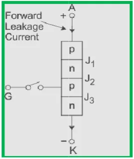
FORWARD BLOCKING MODE
Now considering the anode is positive with respect to cathode, with gate kept in open condition. The thyristor is now said to be forward biased as shown
Fig. No. 9 Forward blocking mode of thyristor
As we see the junctions J1 &
junction J2 goes into reverse biased condition. In this particular mode, a small current, called foreward leakage current is allowed to flow initially as shown in the diagram for characeristic of thyristor shown in fig. no. 9
Forward conduction mode
When the anode to cathode forward voltage is increased, with gate circuit open, the reverse junction J2 will have an avalanche breakdown at forward breakover voltage Vbo leading to thyristor turn on. Once the thyristor is
can see from the diagram for characteristics of thyristor, that the point M at once shifts towards N and then anyywhere between N and K. Here NK represents the forward conduction mode of the thyristor shown in fig. no.8. In this mode of operation, the thyristor conducts maximum current with minimum voltage drop, this is known as the forward conduction or the turn on mode of thyristor.
LM-358 OPERATIONAL AMPLIFIER
An operational amplifier or OP
amplifier with a vey high voltage gain. Op
multistage amplifier in which a number of amplifier stages are connected to each other in a very complicated manner. Its
Sharad Chandra Rajpoot and Prashant Singh Rajpoot, Desing & modeling of scr based controller for speed control of single phase induction motor
emitter current peak = 200mA
Fig. No. 8 thyristor chharactristics
FORWARD BLOCKING MODE
Now considering the anode is positive with respect to cathode, with gate kept in open condition. The thyristor is now said to
Fig. No. 9 Forward blocking mode of thyristor
J3 are now forward biased but junction J2 goes into reverse biased condition. In this particular mode, a small current, called foreward leakage current is allowed to flow initially as shown in the diagram for characeristic of thyristor shown in fig. no. 9.
When the anode to cathode forward voltage is increased, with gate circuit open, the reverse junction J2 will have an avalanche breakdown at forward breakover voltage Vbo leading to thyristor turn on. Once the thyristor is turned on we can see from the diagram for characteristics of thyristor, that the point M at once shifts towards N and then anyywhere between N and K. Here NK represents the forward conduction mode of the thyristor shown in fig. no.8. In this mode of ion, the thyristor conducts maximum current with minimum voltage drop, this is known as the forward conduction or the turn on mode of thyristor.
358 OPERATIONAL AMPLIFIER
An operational amplifier or OP-AMP is a DC-coupled voltage high voltage gain. Op-amp is basically a multistage amplifier in which a number of amplifier stages are connected to each other in a very complicated manner. Its
[image:4.595.53.274.595.712.2]internal circuit consist of many transistors, FETs and resistors. All this occupies a very little space. So, it is picked in a small package and is available in the integrated circuit (IC) form. The term op-amp is used to denote an amplifier which can be configured to perform various operations like amplification, subtraction, differentation, addition, integration etc.
Fig. no.10 operational amplifier Pin configuration circuit diagram (LM-358)
OPERATIONAL AMPLIFIER (LM358)
supply voltage(v+) = 32V maximum
differential input voltage = 32V maximum
input voltage : Minimum = -0.3v
Maximum = 32v
An op-amp has two input terminals and one output terminal. The op-amp also has two input voltage supply terminal as shown above. It has a differential input and a single output. The terminal marked as negative ( - ) is called as an inverting terminal and the terminal marked as positive ( + ) is called as a non inverting terminal of the operational amplifier. If we connect an input signal at the inverting terminal of the op-amp than the amplified output signal is 180 degree out of phase with respect to the applied input signal, wheres if an input is conneced to the non-inverting terminal than the output signal obtained will be in phase i.e it will have no phase shift with respect to the input signal.
Also as seen from the circuit symbol above it has two input power supply terminals +Vcc and –Vcc. For the operation of an op-amp a dual polarity DC supply is essential. In the dual polarity supply the =Vcc is connected to the poitive supply of one power source or battery and the –Vcc terminal is connected to the negative supply of anothe source. However few op-amps can also operate on a single polarity supply. There is no common ground terminal in th op-amp hence the ground has to be established externally. The op-amp offers all the advantages of IC’s such as high reliability, small size, cheap, less power consumption.
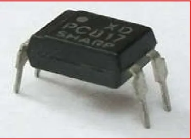
OPTOCOUPLER
An Opto-coupler (also known as optical isolator) is a semiconductor device that uses a short optical transmission path to transfer an electrical signal between circuits or elements of a circuit, while keeping them electrically isolated from each other. These components are used in a wide variety of communications, control and monitoring system that use light to prevent electrical high voltage from affecting a lower power system receiving a signal. In its simplest form, an opto-coupler consist of a light-emitting diode (LED), infrared light emitting diode (IRED) or laser diode for signal transmission
and a photosensor (phototransistor) for signal reception. Using an optocoupler, when an electrical current is applied to the LED, infrared light is produced and passes through the material inside the optoisolator. The beam travels across a transparent gap and is picked up by the receive, which converts the modulated light or IR back into an electrical signal. In the abscence of light, the input and output circuits are electrically isolated to each other. Electronic equipment, as well as signal and power transmission line, are subjected to voltage surges from radio frequency transmission, lightening strikes and spikes in the power supply. To avoid disruption, opto-isolaters offer a safe interface between high-voltage components and low-voltage devices.
Fig.No.11 Opto-coupler
WORKING OF HARDWARE MODEL
WORKING
The single phase ac power supply of 230V, 50Hz is step down by means of a centre tap transformer to get the two polarities which are 180 degree out of phase from each other. This two step down voltage of 12V is applied to a full wave bridge rectifier which converts the AC voltage into pulsating DC voltage. This pulsating voltage is passed through the capacitor to remove filter it. The two voltage regulator (7812 & 7912) is used to get two voltage polarities of +12V & -12V. These two voltages are given to the supply terminal of op-amp. One another centre tap transformer is used to get two polarities of voltage which are 180 degree out of phase. The one polarity is given to the non-inverting terminal of one operational amplifier and another polarity is given to the non-inverting terminal of second amplifier. Since the feedback of both the op-amp is infinity, the voltage produced by it is in the form of rectangular pulses. These pulses are given to the PNP transistor and capacitor.
[image:5.595.335.532.215.358.2]output of the two comparators is PWM signal which are 180 degree out of phase with each other.
This two PWM signal is given to the two opto-isolator which is used to isolate the main working circuit from the AC voltage. The opto-isolaters work on a dc voltage of 5V. Therefore we use two more step down transformer for these two opto-isolaters. The output of the opto-isolaters is given to the gate terminal of the SCRs. The two SCRs are connected anti-parallel. The firing angle of the thyristor can be varied by means of the regulator and hence the speed of the motor is controlled.
ADVANTAGES
Single phase motor is that it requires a two wire supply.
Single-phase motors are less expensive to manufacture
than other motors.
Capacitor-start motors are good general purpose motors
and they are ideal for most occasions.
The single phase motors are simple in construction, cheap
in cost, reliable and easy to repair and maintain.
The current rating of the thyristors is very high and
therefore they will not damage easily.
LIMITATIONS
Single phase motors are that their power is limited.
They do not have good starting torque and they have a
complex starting switch in some cases.
Speed control of induction motors is difficult.
At low loads, the power factor drops to very low values.
RESULT ANALYSIS
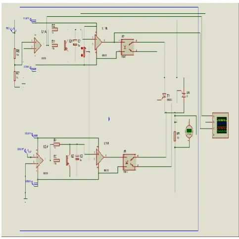
[image:6.595.313.556.74.295.2]SIMULATION MODEL
Fig. No. 12 Simulation model
WAVEFORMS
[image:6.595.309.562.344.512.2]GENERATION OF RECTANGULAR PULSES:
Fig. No. 13. Rectangular pulses
[image:6.595.41.283.506.748.2]GENERATION OF SAWTOOTH PULSES
Fig. No. 14 Saw-tooth pulses
GENERATION OF PWM SIGNAL
Fig. No.15 PWM signal Conclusion
[image:6.595.321.545.564.752.2]Speed-control technique, It represents a design of low high-efficiency drive capable of supplying s single
induction motor with a PWM modulated sinusoidal voltage. The circuit operation is controlled by the pulse generator. device is aimed at substituting commonly used TRIAC phase angle control drives. This circuit is capable of supplying single-phase A.C. induction motor (or general A.C. inductive / resistive load) with varying A.C. voltage. The same as in the TRIAC control, the voltage applied to the load can be varied from zero to maximum value. On the other hand, it uses a pulse width modulation technique (PWM), and when compared to the phase-angle control used for TRIACS, it produces much lower high order harmonics. Because the circuit is aimed at low-cost, low/medium power applications, t does not use a conventional converter technology to produce output voltage waveform. It directly modulates the mains A.C. voltage. Compared to costly converter, it require lower number of active and passive components. In summary, a device attempted here takes advantage of both low price of the phase angle control and low harmonics content and high efficiency that we can get with standard converter technology.
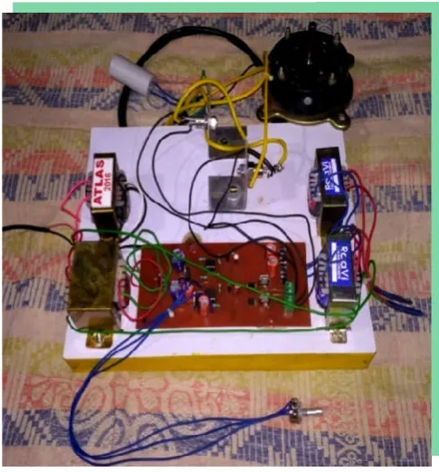
[image:7.595.40.283.329.590.2]Model Structure
Fig. No. 16. Model structure
REFERANCES
Akabari, R. P. and Hitarth buch, 2013. “Modeling of split phase induction motor with single phase cycloconverter,”
Journal of Information, Knowledge and Research in Electrical Engineering,” Vol. – 02, Issue
Oct.
control technique, It represents a design of low-cost, efficiency drive capable of supplying s single-phase A.C. induction motor with a PWM modulated sinusoidal voltage. The circuit operation is controlled by the pulse generator. The imed at substituting commonly used TRIAC phase angle control drives. This circuit is capable of supplying phase A.C. induction motor (or general A.C. inductive / resistive load) with varying A.C. voltage. The same as in the e applied to the load can be varied from zero to maximum value. On the other hand, it uses a pulse width modulation technique (PWM), and when angle control used for TRIACS, it produces much lower high order harmonics. Because the cost, low/medium power applications, t does not use a conventional converter technology to produce output voltage waveform. It directly modulates the mains A.C. voltage. Compared to costly converter, it require lower number d passive components. In summary, a device attempted here takes advantage of both low price of the phase-angle control and low harmonics content and high efficiency that we can get with standard converter technology.
structure
“Modeling of split phase induction motor with single phase cycloconverter,”
Journal of Information, Knowledge and Research in
02, Issue - 02, Nov 12 To
Devandra Kumar Shukla and Sudhanshu Tripathi, “Thyristor controlled power for induction motor,” International Journal of Innovative Research and Studies, Vol. 2, Issue 7, July.
Dr. Jamal, A. 2014. Mohammed,” Speed Control of Single Phase Induction Motor Using Micro
12-13th April.
Dr. P.S. Bimbhra “power electronics” khanna publishers Iba K. 1994. ‘Reactive power optimization by gene
algorithms’, IEEE Trans on No.2, pp.685-692.
Oladepo, O. and Adegboyega,
Simulation of Single-Phase SCR Controller for Single Phase Induction Motor, “International Journal of Electronic and Electrical Engineering, Vol.5, Number 2
Oluwasogo, E.S. and Okakwu,
Analysis Of A Single-Phase Ac Voltage Controller Under
Induction Motor Load,” International Journal of Research
in Engineering and Technology
Phase angle control method of speed control of single phas induction motor (IJIREEICE)
Prashant singh Rajpoot, Sharad Chandra Rajpoot and Durga Sharma,“wireless power transfer due to strongly coupled
magnetic resonance”, international Journal of Science
Engineering and Technology research ISSN 2319 Vol.03,.05,April & May-2014,Pages:0764
Rohit Gupta, Ruchika Lamba, and Subhransu Padhee, “Thyristor Based Speed Control Techniques of DC M A Comparative Analysis, “
Scientific and Research Publications
2012
Sharad Chandra Rajpoot, 2014.
Durga Sharma, “A typical PLC Application in
Automation”, International Journal of Engineering research and TechnologyISSN
2278-Sharad Chandra Rajpoot, Prashant Singh Raj
Sharma,“21st century modern technology of reliable billing
system by using smart card based energy meter”,
International Journal of Science Engineering and
Technology Research, ISSN 2319
April & May-2014, Pages:0840
Umar Farooq Siddiqui, Ajit Verma, and Shilpa Soni, “Comparative Performance Analysis of Induction Motor Using Semiconductor Devices in Terms of Firing Angle,”
International Journal of Emerging Technology and Advanced Engineering, Vol. 4, Issue 2, Fe
*******
Devandra Kumar Shukla and Sudhanshu Tripathi, 2013. “Thyristor controlled power for induction motor,” International Journal of Innovative Research and Studies,
Mohammed,” Speed Control of Single Phase Induction Motor Using Micro-Controller,”
ICIAC-Dr. P.S. Bimbhra “power electronics” khanna publishers ‘Reactive power optimization by genetic algorithms’, IEEE Trans on power systems, May, Vol.9,
Adegboyega, G.A. 2012. “MATLAB Phase SCR Controller for Single Phase Induction Motor, “International Journal of Electronic
l Engineering, Vol.5, Number 2
akwu, I.K. 2014. “Performance Phase Ac Voltage Controller Under
International Journal of Research in Engineering and Technology, Vol. 03, Issue: 06, Jun. Phase angle control method of speed control of single phase
induction motor (IJIREEICE)
, Sharad Chandra Rajpoot and Durga “wireless power transfer due to strongly coupled , international Journal of Science Engineering and Technology research ISSN 2319-8885
2014,Pages:0764-0768.
Rohit Gupta, Ruchika Lamba, and Subhransu Padhee, “Thyristor Based Speed Control Techniques of DC Motor:
A Comparative Analysis, “International Journal of
Research Publications, Vol. 2, Issue 6, June
2014. Prashant Singh Rajpoot and
Durga Sharma, “A typical PLC Application in
Automation”, International Journal of Engineering research -0181 Vol.03, Issue.6, June. Sharad Chandra Rajpoot, Prashant Singh Rajpoot and Durga
century modern technology of reliable billing system by using smart card based energy meter”,
International Journal of Science Engineering and
ISSN 2319-8885 Vol.03, Issue.05, Pages:0840-0844.
Umar Farooq Siddiqui, Ajit Verma, and Shilpa Soni, “Comparative Performance Analysis of Induction Motor Using Semiconductor Devices in Terms of Firing Angle,”
International Journal of Emerging Technology and