~G 2 3 i973
TECHNICAL USER'S MANUAL
VISTA BASIC
and
C. KEttI' RIPLEY
P.O'. B6x ~---....
San Jose, CA.
(408) 377
GENERAL DESCRIPTION
The INFOTON VISTA BASIC CRT Display Terminals are high speed, silent interactive terminals designed for use with an on-line computer. A VISTA BASIC terminal may be used as a substitute for a teletypewriter in a time-sharing application, or as an input/output device in a specialized computer system. The VISTA BASIC is a self-contained desk-top unit which includes keyboard, video display, control and refresh electronics, power supply, and either an EIA or current loop data interface.
DISPLAY CHARACTERISTICS
Characters/ Line Lines/Display Character Set Character Format Character Size Cursor Refresh Rate Viewing Area Color Readability
SCREEN SIZES
32 32 64 64 10 20 10 20 64 character ASCII (Upper Case)
5 x 7 dot matrix 0.10" x 0.15" nominal Non-destructive blinking underscore 50 or 60 Hz
9" x 7"
White - P4 phosphor Screen easily read without disruptive reflections in 100 foot candle illumination MODES OF OPERATION
Full/Half Duplex Full Duplex
Keyboard output to outgoing data line. Display input from incoming data line.
Half Duplex
Keyboard output to display and to data line. Display input from keyboard and data line.
Local/On Line
Local
Data line disconnected. Operation as in Half Duplex.
On-Line
Data line connected. Roll/Page
Roll
When the format rolls up one line, the former top line of the display is lost; the new bottom line is blank. Page
When the cursor is in the last line, any action that would normally move the cursor down one line instead moves the cursor to the corresponding column in the top line.
COMMAND FUNCTIONS Erase Screen
Line Feed, Carriage Return Blink Start, Blink End
Cursor Right, Left, Up, Down, and Home
INTERFACE Data Rates
Maximum data rates are as follows: Asynchronous to I nternal Timing
820 characters/second (When in ROLL mode, input during the rolling action should be limited to 220 ch aracters/second)
Demand- Response
1500 characters/second average Data Interface Modules
Each VISTA BASIC terminal is supplied with either of the following customer-selected interfaces as standard equipment.
Asynchronous Communication Interface, Single Speed (1-101)
SIGNALS IN INTERFACE
RS-232C
Descri ption Pin Number Designation
Transmitted Data 2 BA
Received Data 3 BB
Request to Send 4 CA
Clear to Send 5 CB
Signal Ground 7 AB
Carrier Detect 8 CF
Data Terminal Ready 20 CD
The interface transmits 11 bits at 110 baud, 10 bits at higher speeds. Receives 10 or 11 bits. Parity bit is always a logical "1" (mark). Standard speeds are 110,
150, 300, 600, 1200, 1800, 2400 or 4800 baud.
Speeds up to 8200 baud available on request.
Asynchronous Current Loop (Teletype) Interface, Single Speed (1-102)
For interface to equipment designed for teletype
-writer style 20 or 60 milliampere current loop
operation. Transmits 11 bits at 110 baud, 10 bits at
higher speeds. Receives 10 or 11 bits. Parity bit is always logical "1" (mark). Standard speeds are 110, 150, 300, 600, 1200, 1800, 2400, or 4800 baud.
Speeds up to 8200 baud available on request.
Parallel Interface Capability
All VISTA BASIC units have a backplane slot that is
wired to accept a printed circuit board with a user.-designed custom parallel interface. Signals at T2L
levels are provided for data into memory, data out of memory, keyboard data output, and the necessary control lines for data transfer. Pin allocations and a timing diagram are available upon request.
KEYBOARD
layout
The alphanumeric section is compatible with the Model 33 Teletype. In the unshifted mode, the upper
case code is generated for alphabetic characters.
Rollover
When one key is already depressed and a second key is
then depressed, the code for the second key will not be generated until the first key is released.
Repeat
When a code or function-generating key is depressed
along with the Repeat Key, the code or function will be repeated at a rate of 10 per second.
HOME
CONTROLS, SWITCHES, INDICATORS (F, - Front, R - Rear of Unit)
Controls
Intensity (F)
Horizontal (F)
Vertical (F)
Switches
OFF-ON (F)
LOCAL-LINE (F) ROLL-PAGE (F)
Full/Half Duplex Selector (R)
Indicator
Power On (F)
Mechanical
Size 15" High, 17" Wide, 27" Long Weight - 65 pounds
Environment Temperature Operating: Storage: Hunlidity: Power 125 watts
105 -125 volts, 60 Hz
0° to 40°C
_30° to 70°C
o to 95% non-condensing
105 - 125 volts or 205 - 230 volts, 50 Hz (Export model)
OPTIONS
Integral Modems
One of the following four modems may be supplied with the VISTA BASIC:
INFOTON Product Designation
P-401 P-402 P-403 P-404
Equivalent Western Elec.
Modem
103A 103F 202C 202D
Output from the integral modem attaches to a Data Access Arrangement or to a private communications line.
Numeric Pad
The A-201 Numeric Key Pad contains 10 numeric keys, plus the decimal point for convenient entry of
VISTA STANDARD
SEP 27,91'.\
-
---
-
/- - '
GENERAL DESCRIPTION
The INFOTON VISTA STANDARD CRT display ter-minals are designed for use with an on-line computer as high speed, silent interactive terminal devices. They can be utilized as a substitute for a teletype in a time-sharing environment or, more appropriately, as a means to bring the power of a computer into locations wh ich previously could not afford terminal equipment. Incorporated into
each unit is a keyboard, video presentation, control and refresh electronics, a power supply and an EIA or current loop interface required for on-I ine use with a dataphone, computer or teletype.
DISPLAY CHARACTERISTICS
Characters/Line
Lines/Display Character Set
Character Format
Character size Cursor
Refresh Rate Viewing Area
Color
Readability
SCREEN SIZES
40 40 80 80
10 20 10 20
64 character ASCII (upper case)
5 x 7 dot matrix (upper case) 0.08" x .1 g" nominal
Non-destructive blinking underscore 50 or 60 Hz
g" x 7" White - P4 phosphor
Screen easily read without
disruptive reflections in 100 foot candle illumination
Size Weight
Power
15" high, 17" wide, 27" long 65 pounds 125 watts 105-125 volts, 60 Hz
105-125 volts or 205-250 volts, 50 Hz (Export Model)
Temperature 0° to 40° C (operating) _30° to 70° C (storage) Humidity o to 95% non-condensing
Full/Half Duplex Full Duplex
Keyboard output to outgoing data line. Display input from incoming data line.
Half Duplex
Keyboard output to display and to data line. Display input from keyboard and data line.
Local/On-line Local
Data line disconnected. Operation as in Half Duplex.
On-Line
Data line connected.
Page/Roll Roll
In normal operation, the unit is in roll mode. When
the format rolls up one line, the former top line of display is lost; the bottom line is blank.
Page
The page mode is entered whenever the Page com
-mand (Control "X") is received from data line or keyboard. Whenever the cursor is in the last line, any action that would normally move the cursor down one I ine moves the cursor to the corresponding column in the top line.
COMMAND FUNCTIONS
Erase Screen, Erase to End of Line.
Line Feed, Carriage Return Blink Start, Blink End
Cursor Right, Left, Up, Down, and Home Page Mode.
INTERFACE
Data Rates
Maximum data rates are as follows:
Asynchronous to I nternal Timing
820 characters/second (When in ROLL mode, input during rolling action should be limited to 500 char/sec unless two NULL characters are added after the character which causes the rolling action.)
Demand-Response
1500 characters/second average
Data Interface Modules
Each VISTA terminal is supplied with one of the following customer selected data interface modules as standard equipment.
Asynchronous Serial Communication
Interface, Multi-Speed (1-103)
Nine switchable baud rates (110,150,300,600, 1200,
Asynchronous Serial Current Loop (TTY)
Interface, Multi-Speed (1-104)
Nine switchable baud rates (110, 150, 300, 600, 1200,
1800, 2400, 3600, 4800 bps.) 20 or 60 ma current loop interface to a computer or teletype. Switch
selectable, even or odd character parity or fixed parity bit at logical "1". Transmits or receives 1 0 or 11 bit code.
Parallel I nterface Line Driver (1-106)
Connects interface Port to parallel lines up to 1000 feet or more in length.
ACCESSORY PORTS
All units have three Accessory Ports for interface to
I/O options, peripheral equipment, or special devices.
Each of these ports consists of a printed circuit card socket to accept a printed circuit card as part of the
VISTA electronics package.
KEYBOARD
Layout
The alphanumeric section is compatible with the
Model 33 teletypewriter. In the unshifted mode, the upper case code is generated for alphabetic characters.
Rollover
When one key is already depressed and a second key is then depressed, the code for the second key will not be generated until the first key is released.
Repeat
When a code or function-generating key is depressed along with Repeat key, the code or function will be repeated at a rate of 10 per second.
SWITCHES, CONTROLS, INDICATORS (F - Front, R - Rear of Unit)
Controls
Intensity (F) Horizontal (F) Vertical (F)
Switches
OFF-ON (F) LOCAL-LINE (F) Data Rate Selector (R)
Odd-Even-Mark Parity Selector (R) Full/Half Duplex Selector (R)
HOME
20/60 mao Selector (with current loop interface only) (R)
Indicators
Power On (F) Carrier On (F) (with integral modem)
Parity Error (F)
'. ... , . ~_ .~.~;.~l\
OPTIONS ,":J~l ,~tKl,.~~{·
..
~llI t rf ' ~ ~n,.rj)"'~:"·· *", ",",0. n e ace t, .. .l"~D,"1I '"1f\'~ .... . .'.'
Multipurpose Asynchronous Seri~~~ ~ .... t~ ~-r::' ,q Interface Multi-Speed (1-105bat~.* .•
t.
:
:>
.l")?~f" .,~ 'Contains capabilities of both ASY-rl's:jm;lQOUS Serier! , .• , Communication Interface Multi-Sp~ed '(i~l'03); and
Asynchronous Serial Current Loop (TTY) Interface,
lVIulti-Speed (1-104).
Peri pherals:
Printer Interface (P-101)
An interface circuit provid ing a serial output to a printer, "on command." Several terminals can share one printer. Appropriate switches and indicators are mounted on the front panel and keyboard of the
VISTA.
Integral Modem (P-401 - P-404)
A modem built into the VISTA. A choice of 103 A, F or 202 C, D modems is available. Output connects to
Bell System Data Access Arrangement or private lines.
I ndicators are mounted on the front panel of the
VISTA.
Answerback (P-303)
Standard teletypewriter answerback function -gener
-ates a sequence of up to 39 hardware programmed characters upon receipt of WRU code from data line or use of the "HERE IS" key.
Accessories
Numeric Key Pad (A-201)
An additional eleven-key, keyboard mounted matrix
for more rapid entry of numeric data.
Lower Case Character Group (A-202)
96 character ASCII. I ncluding displayable lower case character set. Lower case characters are presented in a
5 x 9 dot matrix. Keyboard has ANSI layout.
Infotone (Bell) (A-203)
A bell rings when the cursor reaches the tenth position from the end of line or when the BELL code is received from the computer.
Light Pen -(A-204)
I ncludes photo-detecting light pen, associated circuit-ry and interface electronics. The light pen will cause the transmission of a message containing the row and column position of the character at which the pen is pointed.
INFOTON INCORPORATED • SECOND AVENUE, BURLINGTON. MASSACHUSETTS 01803 • AREA CODE 617 272-6660
SUBSIDIARY OF OPTICAL SCANNING CORPORATION
INFOTON
TECHNICAL USER'S MANUAL
VISTA BASIC
and
VISTA STANDARD
#00744-Rev. B
INFOTON INCORPORATED • SECOND AVENUE, BURLINGTON, MASSACHUSETTS 01803 • AREA CODE 617 272-6660
SUBSIDIARY OF OPTICAL SCANNING CORPORA TlON
PRE F ACE
This manual presents basic information necessary for the user of the INFOTON VISTA BASIC and VISTA STANDARD display terminals.
The symbol ++ is used in the margin throughout this
manual to indicate extended features that are not
INFOTON INCORPORATED. SECOND AVENUE, BURLINGTON, MASSACHUSETIS 01803. AREA CODE 617 272-6660
INFOTON
TECHNICAL USER'S MANUAL VISTA BASIC and STANDARD
TABLE OF CONTENTS
INTRODUCTION
SUMMARY OF CHARACTERISTICS
Interchangeable with Teletype Silent Operation
Easy-to-Read Characters
High-Speed Transmission Rates Choice of Computer Interface Roll or Page Mode
Cursor Control
Erase Page and Erase to End of Line Blink Mode
Variety of Options Remote TV Monitors
FUNCTIONAL DESCRIPTION On ... Line/Local
Full-Duplex/Half-Duplex Interface
OPERATIONAL FEATURES
Teletypewriter Compatibility Cursor
Roll Mode Page Mode Blink
Response to Commands
#00744-Rev. B 18 February 1972
Page No.
2
2 2
2
2
2
2
3
3
3
3
3
4
4 4
4
6
6
6
7
8
8
INFOTON INCORPORATED. SECOND AVENUE, BURLINGTON, MASSACHUSETIS 01803. AREA CODE 617 272-6660
Page Mode Erase Screen
Erase to End of Line Carriage Return
Line Feed Null
Rub-Out Break
Print Page Home
CUTsor Right CUTsor Left Cursor Up Cursor Down
Blink Start, Stop
EQUIPMENT DESCRIPTION Keyboard
Display
Control Logic Controls
Power Intensity
Horizontal/Vertical Continuous Print Parity Light Carrier Light
Mechanical Specifications Environment Specification
#00744-Rev. B 18 February 1972
INFOTON INCORPORATED • SECOND AVENUE, BURLINGTON, MASSACHUSETIS 01B03 .AREA CODE 617 272-6660
INTERFACES
Introduction 19
Asynchronous Serial Interface 19
VISTA STANDARD Interfaces 21
Multipurpose Asynchronous Serial Interface 21
Current Loop Interface 24
Parallel Interface 27
VISTA BASIC Interfaces 29
OPTIONAL FEATURES 32
Answerback Option (P-303) 32
Numeric Pad (A-20l) 32
Lower Case Option (A-202) 32
Printer Interface (P-lOl) 32
Infotone (A-203) 33
Power Lock (A-20S) 33
Tektronix 4S0l Scan Converter Interface (A-30l)33
Light Pen (A-204) 33
OPERATING INSTRUCTIONS Initial Setup
Establish Communication
Appendix A - VISTA Code Set
Appendix B - VISTA Input-Output Codes
Appendix C - Multipurpose Asynchronous Serial Interface EIA Signals and Pin Connectors
Appendix D - Parallel Interface Signals
1I00744-Rev. B
18 February 1972
34 .'
34 34
37
38
43
INFOTON INCORPORATED. SECOND AVENUE, BURLINGTON, MASSACHUSETTS 01803. AREA CODE 617 272-6660
LIST OF FIGURES
Figure 1.1
-
VISTA Display Terminal 1Figure 3~1
-
Modes of Operation and Communication 5Figure 5.1
-
Basic Keyboard (ie. , upper case only) 12Figure 5.2
-
Dot Matrix Characte·r Format 15Figure 5.3
-
Dot Matrix with Cursor 16Figure 5.4 - Lower Case Dot Matrix 16
Figure 5.5 - Control Panel 17
Figure 6.1 - MASI Interface Panel 23
Figure 6.2 - Data Rate versus Cable Length as a Function of Signal Level for INFOTON
Current Loop Interfaces 25
Figure 6.3 - VISTA STANDARD Current Loop Connections 26
Figure 6~4 - VISTA BASIC Current Loop Connections 31
INFOTON INCORPORATED. SECOND AVENUE, BURLINGTON, MASSACHUSETIS 01803. AREA CODE 617 272-6660
1. INTRODUCTION
Eigure 1.1 VISTA Display Terminal
The INFOTON VISTA Display Terminal (Figure 1.1) is an alphanumeric display that can be used in a wide range of applications requiring man/computer interaction.
The VISTA is designed to communicate with any computer, connected either directly or over standard telephone lines. The unit is completely compatible with systems and software
designed for Model KSR 33 or 35 teletypewriters. To the
computer the VISTA looks like a teletypewriter except that it can communicate with the computer at much higher speeds.
The VISTA is extremely flexible in its basic form and can be used without modification in most system applications. A varietyof options are available to satisfy those applications which require special hardware features.
#Q0744-Rev. B 18 February 1972
-1-INFOTON INCORPORATED. SECOND AVENUE, BURLINGTON, MASSACHUSETTS 01 B03 • AREA CODE 617 272-6660
2. SUMMARY OF CHARACTERISTICS
INTERCHANGEABLE WITH TELETYPE
The VISTA can be substituted for a Model 33 or 35
teletype with no hardware or software modifications. The
VISTA can serve as an upgraded high speed terminal to all time-sharing services using ASCII* Code regardless of the computer system used by the service.
SILENT OPERATION
The VISTA is completely silent in operation.
EASY-TO-READ CHARACTERS
High resolution, non-reflecting screen, and contrast-enhancing filter permit easy viewing at distances up to 10 feet under direct glare and 100 foot candle illumination.
HIGH-SPEED TRANSMISSION RATES
Speeds up to 4800 bps serial or 1500 char/sec parallel are available.
++ Nine switch-selectable transmission rates from 110 up
to 4800 bps are available in the standard unit.
CHOICE OF COMPUTER INTERFACE
The unit is supplied with choice of interface modules; serial asynchronous interface, either EIA RS-232C standard or
20/60 rna TTY style current loop. Parallel data interface is
available on the VISTA STANDARD.
ROLL OR PAGE MODE
The VISTA is normally in Roll Mode. The unit may be
switched to Page Mode from the keyboard or the data line. Erase
Screen command returns the unit to Roll Mode.
*
American Standard Code for Information Interchange.#00744-Rev. B
-2-INFOTON INCORPORATED • SECOND AVENUE, BURLINGTON, MASSACHUSETIS 01803 .AREA CODE 617272-6660
CURSOR CONTROL
The unit has a non-destructive position marker or cursor.
The cursor displays as a blinking underscore. The cursor
position can be tracked and manipulated by the computer or the operator.
ERASE PAGE AND ERASE TO END OF LINE
The full screen may be erased with one command.
++ With another command, the unit will erase all characters
from the'cursor position to the end of the line in which the cursor resides.
BLINK MODE
The VISTA can blink selected words or groups of words in
order to attract attention to all or specific parts of the screen.
VARIETY OF OPTIONS
In addition to the basic VISTA, a variety of options is available, including printer, automatic answerback, lower case
characte~s, and light pen.
#00744-Rev. B 18 February 1972
-3-INFOTON INCORPORATED. SECOND AVENUE, BURLINGTON, MASSACHUSETTS 01 B03 • AREA CODE 617 272-6660
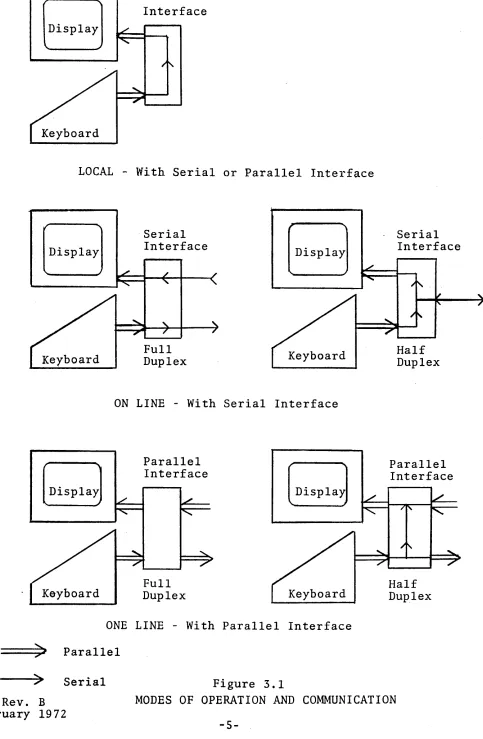
3. FUNCTIONAL DESCRIPTION
The VISTA terminal is a completely self-contained desk top unit operating independently of any other VISTA terminal
in a system. The unit consists of a keyboard, video monitor,
refresh memory, control logic, and a computer or modem
inter-face. The modes of operation, communication and interface
are illustrated in Figure 3.1 and are described below.
ON-LINE/LOCAL
The VISTA has two modes of operation: ON-LINE, with the terminal connected to the data line, and LOCAL, with the
terminal disconnected from the data line. LOCAL/ON-LINE
selection is made using a switch located on the front panel of the terminal.
FULL-DUPLEX/HALF-DUPLEX
There are two modes of communication to the data line as
shown in Figure 3.1 - Full Duplex (FDX) or Half Duplex (HDX).
FDX/HDX mode is selected by a switch on the rear of the unit. In Full Duplex mode, information will be displayed only if the computer at the end of the data line echoes back the information
transmitted from the keyboard. All computers to which the
VISTA may be connected do not necessarily have this Full
Duplex or Pecho back" capa1?ility. In the Half-Duplex mode,
data entered on the keyboard is routed to the display - the computer does not echo data back.
INTERFACE
Two general types of interfaces are available, serial
and parallel as illustrated in Figure 3.1. The various modes
in which the unit may be used are also shown in Figure 3.1.
# 0 0744 - Rev. B 18 Febru.ary 1972
4-Interface
LOCAL - With Serial or Parallel Interface
[DiSPlay]
Keyboard
Serial Interface
Full
Duplex Keyboard
ON LINE - With Serial Interface
Parallel Interface
Full
Duplex Keyboard
ONE LINE - With Parallel Interface
==:;»JI
ParallelFigure 3.1
Serial Interface
Half Duplex
Parallel Interface
Half Duplex
--->~ Serial
#00744-Rev. B MODES OF OPERATION AND COMMUNICATION
18 February 1972
[image:19.612.76.559.49.788.2]-5-INFOTON INCORPORATED. SECOND AVENUE, BURLINGTON, MASSACHUSETIS 01803. AREA CODE 617 272-6660
4. OPERATIONAL FEATURES
TELETYPEWRITER COMPATIBILITY
The VISTA reacts to the full ASCII character set, (Appendix A)
receiving and storing both upper and lower case codes. For
this reason, the VISTA can be used. without ,software modifi-cation in applimodifi-cations which are now using a teletypewriter
Model 33 or 35. The effect of each ASCII code on the VISTA
is shown in Appendix B. All characters are displayed as
upper case characters, unless the unit is equipped with the
lower case character option. Although the terminal may be
programmed as a teletypewriter, the full advantages of the VISTA as an interactive terminal are realized whenfue software makes full use of the unit's features described in the following sections:
CURSOR
The cursor is a unique character appearing on the display
at all times. The cursor indicates the position at which the
next data character will be displayed. It also indicates the
end position of data transmission to the computer. The "Home"
position for the cursor is the first position on the first
line of the display, i,e" the upper left-hand corner of the
display.
The cursor appears on the display screen as a blinking
underscore. It blinks approximately five times a second. The
blinking prevents the operator from losing track of the cursor. The cursor will advance one step for each character that is
typed. The cursor can be positioned by the cursor control keys
or from the data line. There are five cursor movement commands
and corresponding keys: Home, Cursor Down, Cursor Up, Cursor
Left, Cursor Right which the VISTA recognizes as cursor
movement commands. The "Carriage Return" and "Line Feed"
codes also generate cursor movements. All these commands allow
H00744-Rev. B
18 February 1972
-6-INFOTON INCORPORATED. SECOND AVENUE. BURLINGTON. MASSACHUSETTS 01803. AREA CODE 617 272-6660
the operator or the computer to manipulate the cursor to any position on the screen.
The cursor is "non-destructive". In response to one of
the cursor movement commands, the cursor moves but does not alter any data appearing on the screen.
The actual position of the cursor cannot be directly read
by the computer. However, since all cursor movements entered
by the operator on the keyboard are transmitted to the computer, the computer can at all times follow the position of the cursor. This feature allows software editing of a page of textual data on the screen.
The computer can move the cursor to any X-Y coordinate by embedding the appropriate sequence of cursor movement characters
in a message being sent to the VISTA. An efficient cursor moving
algorithm can be constructed by using the "wrap-around" feature
of the cursor movement at the edges of the screen. For example,
the computer program or operator can move the cursor from the Home position to the lower right-hand corner with a single Cursor-left command.
ROLL MODE
The VISTA STANDARD is normally in Roll Mode. The VISTA BASIC
is put in Roll Mode by appropriately setting the manual switch on
the front panel. In this mode, when the screen fills, the data
on the screen rolls up one line; the former top line is lost and
the bottom line is blank. The data appears to roll up. As line
after line of text is written on the screen, the visual effect is that of a continuous scroll of text moving past a window.
Rolling is caused when the cursor is anywhere on the bottom line and a LINE FEED character is received by the terminal.
Rolling is also caused when the cursor is in the bott-om right-hand corner of the screen and any displaying code is received.
Cursor movement from one of the five basic cursor commands
(Home, Cursor Right, Cursor Left, Cursor Up, and Cursor Down)
H00744-Rev. B 18 February 1972
-INFOTON INCORPORATED • SECOND AVENUE, BURLINGTON, MASSACHUSETTS 01803. AREA CODE 617 272-6660
will not move the screen at all. When the curSOT is in the bottom line, Cursor-Down moves the cursor to the top line without rolling. From the bottom right position Cursor-Right moves the cursor to the top left position without rolling. This prevents inadvertent rolling during cursor manipulation by the operator.
In Roll Mode, characters can be transferred at a maximum fixed rate of 500 characters/second (220 characters/second,
on VISTA BASIC). Higher rates can be attained in parallel
demand-response mode which will be discussed in Section 6, INTERFACES.
PAGE MODE
In Page Mode, whenever the cursor is in the last line, any action that would normally cause the data to roll does not roll the data; instead, the new data is written on the top line
of the screen, writing over the old data on the top line. In Page Mode, characters can be transferred at a maximum fixed rate of 820 characters per second, in'serial mode. Higher rates can be attained in parallel demand-response mode which
will be discussed in Section 6, INTERFACES. On the VISTA STANDARD,
the Page Mode is entered whenever the Page Command is received from the data line or keyboard.
++ The unit is switched from Page Mode to Roll Mode whenever the
ERASE command is received from the data line or keyboard. On
the VISTA BASIC, the Page Mode is entered by setting a manual switch on the front panel of the unit.
BLINK
Any set of characters in any portion of the screen may
be blinked. Blinking begins at the cursor position at which the
Blink Start character is received; it stops at the cursor position
at which the Blink Stop character is received. Any number of
groups of characters may be blinked. The Blink Start and Blink
Stop characters display as blank spaces on the screen.
#00744-Rev. B 18 February 1972
-8-INFOTON INCORPORATED. SECOND AVENUE, BURLINGTON, MASSACHUSETIS 01803 • AREA CODE 617 272-6660
RESPONSE TO COMMANDS
The VISTA terminal is controlled and manipulated from
its data stream. The data stream control logic is defined as
follows:
1. Certain characters are designated as command
characters (Appendix B).
2. The computer inserts these characters within
the text transmitted to the VISTA.
3. When accepting the data, the VISTA
continually monitors the input data stream for these command characters, performing a designated action upon reception of a command character. For example, when a Blink Start command character is received by the VISTA, the unit turns on the Blink feature and all characters from that position to the end of the screen will be displayed as blinking characters by the VISTA until
a Blink Stop character is received.
The commands which are used to control the display are described below:
++ PAGE MODE - Puts the unit in Page Mode. Roll Mode is restored
when the screen is erased.
ERASE SCREEN - All data on the screen is erased. Cursor moves
to Home position.
++ ERASE TO END OF LINE - Erases all data from, and including,
the cursor position to the end of line.
When the ERASE TO END OF LINE command is used, characters' can be transferred at a maximum fixed rate of 500 characters/
second, either in parallel or serial mode. However, if one
NULL character is inserted after each ERASE TO END OF LINE command sent to the unit, then a message may be transmitted
#00744-Rev. B 18 February 1972
-9-INFOTON INCORPORATED. SECOND AVENUE, BURLINGTON, MASSACHUSETIS 01 B03 • AREA CODE 617 272-6660
at a maximum rate of 760 characters/second. If twoNJLLS are
inserted, then an 820 character/second rate may be attained.
CARRIAGE RETURN - Places cursor at left most position of the line in which the cursor resides.
LINE FEED - Places cursor on the next line at the same position in which the cursor previously resided.
NULL - (Not generated from the keyboard) No action is taken
when this code appears on the line.
RUB-OUT - When received, no action is taken.
BREAK - (Keyboard Only) Places "space" (logical "0") condi tion
on the data line as long as key is depressed.
++ PRINT PAGE - If the unit is equipped with the Printer Interface
Option, this code causes the page of data on the~reen to be
transmitted to the printer. The data on the screen is not
erased,
HOME - Positions the cursor to the top left position.
CURSOR RIGHT - Places cursor one position to the right of
present position, If cursor is in last character of line, the
next position is first position in the line below or in the home position if the cursor is in the last line.
CURSORLHFT - Places cur"sor one position to left of present
position. If cursor is in first character of line, the next
position is last position of the line above.
#00744-Rev. B 18 February 1972
-10-INFOTON INCORPORATED. SECOND AVENUE. BURLINGTON. MASSACHUSETIS 01803 • AREA CODE 617 272-6660
CURSOR UP - Places cursor one position above the present position . . If cursor is in the first line, the next position
is in the bottom line.
CURSOR DOWN - Places cursor one line below present position. If cursor is in the last line, the next position is in the top line.
BLINK START, STOP - All characters between cursor positions at which Blink Start and Blink Stop are commanded will blink. Blink Start and Blink Stop each are non-displayed characters. The positions at which they occur on the screen are blank. Blinking may be stopped by writing any character or Space in the Blink Start positions.
#00744-Rev. B
18 February 1972
-11-INFOTON INCORPORATED .SECOND AVENUE, BURLINGTON, MASSACHUSETIS 01803 .AREA CODE 617 272-6660
5. EQUIPMENT DESCRIPTION
The.basic VISTA unit logically and physically consists
of three parts, keyboard, display, and control. These
components and the controls and indicators on the unit are described in this section.
KEYBOARD
The operator interacts with the VISTA and with the
computer via the keyboard.· (Figure 5.1)
! II $
1 2 3 4
x
CST RUB BRK BLINK ESC OUT
END
% & ( )
5 6 7 8 9
SPACE
VISTA BASIC KEYBOARD
BRK B~1K ESC RUB END OUT
SPACE
ERASE PAGE
-ERASE PAGE
VISTA STANDARD KEYBOARD
Figure 5.1
Keyboard (ie., upper case only)
It 0 0 744 - Re v. B
18 February 1972
-12-HOME
t
HOME
INFOTON INCORPORATED. SECOND AVENUE. BURLINGTON. MASSACHUSETTS 01803 • AREA CODE 617 272·6660
The VISTA BASIC and STANDARD are character oriented (conversational) terminals, not buffered terminals*; as soon
as a key is depressed, the associated code for the key is instantly transmitted to the computer.
Most keys on the keyboard are the normal printing characters and standard carriage controls found on teletypewriter or electric
typewriter keyboards. The arrangement, key shape, and touch
pressure are similar to an electric typewriter.
The keyboard consists of coded keys (eg. A, B), function keys (eg. REPEAT, BRK) , and mode keys (SHIFT, CTRL).
The basic VISTA can generate 96 ASCII codes; all 128 ASCII codes can'be generated if the unit is equipped with the
lower case option.
Appendix B illustrates the full code set, how to generate the codes from the keyboard, and the effect of the codes on the display.
Both the SHIFT key and the CTRL key establish a mode for the keyboard; i.e., data is not actually generatedmtil a
coded key is depressed. Depressing the SHIFT key in conjunction
with another key causes upper case characters to be transmitted. The keyboard on the VISTA, without the lower case option
generates upper case codes for the alphabetic characters whether
or not the SHIFT key is depressed, For the sake of operator
convenience, two SHIFT keys are on the keyboard. Each of these
keys has the same effect on the data.
Control codes do not display, but in most applications
are used as function codes. Some of the Control codes have
been used as functions on the VISTA. For example, Control L
erases the screen on the VISTA. Some of the function codes
are generated by depressing SHIFT and CTRL in conjunction with
a coded key. An example of this is the Control Shift M code
*The VISTA PLUS is a buffered display terminal.
#00744-Rev. B
18 February 1972
-13-INFOTON INCORPORATED. SECOND AVENUE, BURLINGTON, MASSACHUSETTS 01 B03 • AREA CODE 617 272-6660
which is a cursor-down command. To simplify the entry of
commands from the keyboard, function keys are provided for
all commands. When depressed, the key labeled
'0
generatesthe cursor-down command (Control Shift M).
The REPEAT key when depressed in conjunction with a coded key or function key generates repeated transmission of the code or function at a rate of 10 characters per second.
The BREAK key places "space", i, e., a logical
"0"
condi tion,on the data line for as long as the key is depressed. The BREAK
,key operates with any of the Serial Asynchronous Interfaces discussed in Section 6.
++ Depressing the I/O RESET key,
resets the state of all peripheral options which are attached to the unit.
resets the parity indicator. homes the. cursor.
This key does not transmit any data to the data line and does not alter any data on the screen,
The keyboard has an interlock feature and a roll-over feature which govern operation when two coded keys are simul-taneously depressed.
When one key is already depressed and a second key is then depressed, the code for the second key will not be generated
until the first key is released ("interlock"). Upon release
of either key, the code for the other key is generated ("roll-over") provided that this key remains depressed.
DISPLAY
The display screen is a cathode~ray tube (CRT) with P4
phosphor. The viewing area of the display is 9" wide and 7"
high. A variety of display formats is available in the VISTA
series, The VISTA is available in a 10 or 20 lihe format. The
VISTA BASIC is available with 32 characters per line or 64 character per line, and the STANDARD is available with 40 characters per
line or 80 characters per line.
#00744-Rev. B
-14-INFOTON INCORPORATED. SECOND AVENUE, BURLINGTON, MASSACHUSETIS 01B03. AREA CODE 617 272-6660
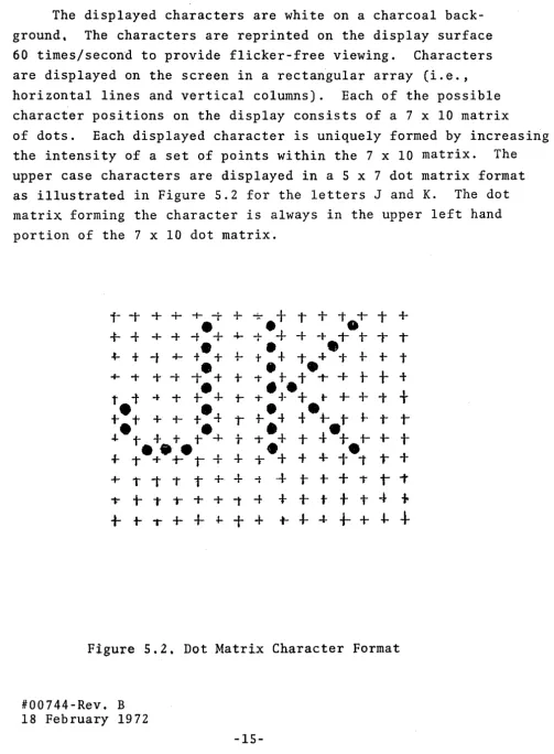
The displayed characters are white on a charcoal
back-ground. The characters are reprinted on the display surface
60 times/second to provide flicker-free viewing. Characters
are displayed on the screen in a rectangular array (i.e.,
horizontal lines and vertical columns). Each of the possible
character positions on the display consists of a 7 x 10 matrix
of dots. Each displayed character is uniquely formed by increasing
the intensity of a set of points within the 7 x 10 matrix. The
upper case characters are displayed in a 5 x 7 dot matrix format
as illustrated in Figure 5.2 for the letters J and K. The dot
matrix forming the character is always in the upper left hand
portion of the 7 x 10 dot matrix.
i-
-r
+
+
+ -t + -::-+
I+
t.1-T
++ -{-
+ -I-,.-+
4--+.+
+
-l- 1- t- T T-t-
+
-t
+- te
+
+-
te
+
-t +-1-+-
+
t•
••
+ -t + -t
-t
+
+
-t.+.t
-t'+
t
t
tt.t ....
+t-:+
t- T+
+
t-+-
+-
t
t
t
t
+ + t+
Tr
e
4t·~
t
~
T
T
.J..
t
+
+ te
+
t-t.
+
+
-l--+
t- i-t
+
...-e+.:+_,+
+
+.+
t+
tet
T+
+ i 1" T t
+.
+
-t-+
t-+
+
1"r
T- t - + T T + + 1 ' - f
+ + t t t - t
+
+
t-.++.J-++
t--t--I-i-+++
Figure 5.2. Dot Matrix Character Format
1I00744-Rev. B 18 February 1972
[image:29.617.71.574.76.760.2]-15-++
INFOTON INCORPORATED. SECOND AVENUE, BURLINGTON, MASSACHUSETTS 01 B03 • AREA CODE 617 272-6660
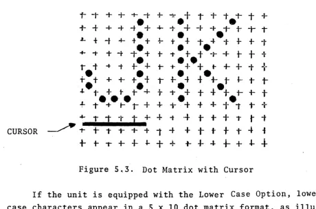
The position of the cursor within the 7 x 10 matrix is
illustrated in Figure 5.3.
r
-t+
+
+ -t + ~+
I+
t.-r
T ++
-t + -I- -te+
4--1--+
-I- + 1- t- T TL f -t 4-
t·
+
+-
+.
+
1- -l---I-
+-
+
t+ ;-
+
-t -t • + 1-1".
tt
·-r
+
t
+
-1-•
••
't t .... -t t- + +-.t-
+
+
t-+-+
T+
•
•
••
+.+
++
+
t
~ ~ i f ~t
~ ~ ~"- t • • •
+
t+.+
t1-.+
•
+
4-
e·
+.
1- -l-t
. t . " t +t - . + + + + f + t i
T+~
-r
T -tt
+.+
-t-+
t+
+
tt
tCURSOR
~
1-+
T T+
+
1 ;.
+
t-
t+
t-t
i [image:30.620.52.513.127.431.2] [image:30.620.154.456.466.666.2]+-
t- 1"" i--I-
~+
+
-t-4-
-I-+-
+
-I-+
Figure 5~3. Dot Matrix with Cursor
If the unit is equipped with the Lower Case Optio~,
case characters
in Figure 5 • 4 .
-l-
+-+ -I-1-+
-I-+
+ + T#0074-4- Rev. B
18 February 1972
appear in a 5 x 10 dot matrix format,
-I-
+
+
++ +
-t+
+.1-
i- t-+
i-++
+
-t-+
+;
tT.
-t- 1- T +,..
+ -...
-I- i- + + ... -+ -t- -r- t- T -4-;--I-
+
1-+
t
•
+ -t i- T•
+••
+.1- "t- or
•
•
T
+
+ -t-+
+--t -t- -r.+.-t+
+
+
+
+•
;- + -1-
+
+ ;- + + -t+
+ ,...
+
•
•
•
;- + + +.-t .. -t + +
+
+
+
1-•
•
••
+
+
+
+
+ t- I t + i- t-+
+
-r•
•
+
T +t
1- T+
-t- i- t-+
T ++
••
.+
-f:- + 1- + ;- t+
+ i- t- T T+
t i- T t
+
-t t + t i- t- tt
+
Figure 5.4
Lower
Case
Dot Matrix
-16-as
lower
INFOTON INCORPORATED • SECOND AVENUE. BURLINGTON. MASSACHUSETIS 01803. AREA CODE 617 272-6660
CONTROL LOGIC
The Control Logic contains the logic, power supply, central timing and control, refresh memory, character generator and
Communications Interface. The most important functions of the
Control Logic are:
CONTROLS
Stores in a refresh memory, all data entered via the keyboard, or received over the communication line.
• Converts the ASCII characters into dot matrix form and presents them on the CRT.
Maintains the display by refreshing the image 60 times/second.
• Provides the electrical interface between the electrical operating levels of the VISTA and the equipment with which the terminal is
operating. The standard interfaces are described
in detail in Section 6.
• Decodes command codes received on the data line and performs the appropriate function.
There are several operator controls and indicators in
addition to the keyboard. These are shown in Figure 5.5 and
are described below.
VISTA BASIC
BOIUZ
VISTA STANDARD
1I00744-Rev. B Figure 5.5
18 February 1972
-17-INFOTON INCORPORATED. SECOND AVENUE. BURLINGTON. MASSACHUSETIS 01803. AREA CODE 617 272-6660
POWER - In the ON position the terminal is in the operating
state. In the OFF position, power is removed from the terminal.
After the .switch is turned to ON, a 30 second warm-up period
is required before operating the terminal. The POWER light
glows when power is applied to the unit.
The power requirements for the unit are:
125 watts; 105-125 volts; 60 Hz or 105-125, 205-250 volts; 50 Hz (Export model)
INTENSITY - This knob allows the screen brightness to be adjusted for the operator's viewing comfort.
HORIZONTAL/VERTICAL - The HORIZONTAL and VERTICAL controls allow
adjustment. for a stable picture. They correspond to the controls
normally found on a commercial television set. Once these controls
are set, they require no further adjustment during the operating period.
++ CONTINUOUS PRINT - This switch effects operation only when the
unit is equipped with the Printer Interface Option. When in
the COPY position, incoming data to the VISTA is also routed
to the printer. This option is further explained in Section 7,
OPTIONAL FEATURES.
++ PARITY LIGHT - Glows when a parity error occurs. Depressing
I/O RESET on the keyboard turns the PARITY light off.
MECHANICAL SPECIFICATIONS - The uni t' s size is 15" high, 17" wide, 11
27" long; Weight 65 pounds.
ENVIRONMENT SPECIFICATION - The temperature requirements are:
Operating 00 to 400C
Storage _300 to 700C
Humidity must be 0 to 95% noncondensing.
#00744-Rev. B
18 February 197"2
-18-~ 1
INFOTON INCORPORATED. SECOND AVENUE, BURLINGTON, MASSACHUSETIS 01803 • AREA CODE 617 272·6660
6. INTERFACES
INTRODUCTION
The VISTA operates with a computer either over telephone
lines via a modem, or locally connected by direct cable. The
standard interfaces accommodate a wide range of computer
sys-tems and a wide range of data rates. This has been accomplished
by adhe~ing to commonly accepted standards for data transmission
mode, transmission method (asynchronous), and transmission rate ..
The Interface Module chosen depends upon the communications
environment in which the terminal will be used. The Interface
Module makes the necessary conversion between the electrical operating levels of the VISTA and those of the particular
external circuit or computer with which the Interface Module is
designed to operate. Also, the interface arranges data in the
format required by the circuit or computer.
ASYNCHRONOUS SERIAL INTERFACE
Using this interface, the VISTA communicates in
bit-serial, character asynchronous mode. Asynchronous is the
transmission method in which the timing information is derived
from each character transmitted. The term asynchronous is
synonymous with START-STOP and implies that the receiver comes
to rest between characters. The START bit allows the receiving
VISTA to initiate its timing in proper synchronism with the
incoming data. The STOP bit(s) ensure that the communication
line is returned. to the marketing condition ready for a new START.
Input and output data characters contain 11 bits compatible
with the KSR 33/35 teletype. However, the unit in receiving,
will operate with 10 or 11 bit formats. The VISTA transmits
in 11 bit format to be compatible with TTY devices at 110 baud. At higher speeds than 110 baud, the unit transmits 10 bits.
(NOTE: On a special order, 11 bits can be transmitted at all
speeds.)
1t00744-Rev. B
-19-INFOTON INCORPORATED. SECOND AVENUE, BURLINGTON, MASSACHUSETIS 01 B03 • AREA CODE 617 272-6660
The following bit configuration and character structure is used by the Asynchronous Interface:
Bit:" 1. START - "space" polarity - first bit
transmitted
2. b 1 - at least significant data bit
3. b 2 - data bit
4. b 3 - data bit
S. b 4 - data bit
6. b 5 - data bit
7. b 6 - data bit
8. b 7 - most significant data bit
9. Parity bit (this bit is always set to 1, i.e.,
mark polarity, on the VISTA BASIC)
"10. STOP - "mark" polarity
11. STOP - "mark" polarity (Note comments above on
11th bit) ~
When the interface is transmitting, it"adds the start bit, computes and adds the parity bit, and adds the stop bit to
every seven-bit code being sent. When it is receiving, it
removes the start and stop bits, and transfers only the seven information bits to the appropriate logic.
++ When receiving, parity is checked.
Transmission is always initiated with the start bit. Bits
b 1 through b 7, shown above, bear a one-to-one correspondence
with the bits b 1 through b 7 of the ASCII code. (Ref. Appendix
B) The "Space" and the "Mark" polarities are as defined by the
EIA Standard RS-232C.* Even parity implies that the total number
of ones in every character should be an even number; odd implies that it should be odd.
* This is the accepted interface standard for serial data
trans-mission which is adhered to by the communication carriers. It
was formed by the Electronic Industries Association and issued
as specification, RS-232. Version C is the current version of
the specification.
#00744-Rev. B
-20-INFOTON INCORPORATED. SECOND AVENUE, BURLINGTON, MASSACHUSETIS 01803. AREA CODE 617 272-6660
VISTA STANDARD INTERFACES
The VISTA STANDARD contains the customer's choice of one of the following interfaces;
· Asynchronous Serial Communications Int'erface (I -103) · Asynchronous Serial Current Loop (TTY) Interface (1-104) · Parallel Interface (1-106)
As an option, the VISTA can be equipped with the Multipurpose Asynchronous Serial Interface (1-105) which incorporates the
capabilities of both the 1-103 and 1-104 interfaces. The
Multipurpose Asynchronous Serial Interface (MASI) and the Parallel Interface are described in this section.
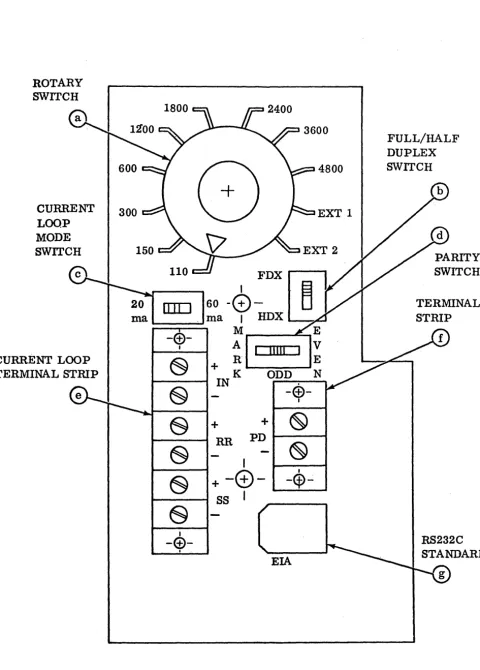
MULTIPURPOSE ASYNCHRONOUS SERIAL INTERFACE
The MASI is mUltipurpose in the sense that it fully provides many interfaces in one printed circuit card. MASI provides an
exposed panel in the rear of the unit (see Figure 6.1) by which the customer can select anyone of a number of computer inter-faces using anyone of a number of data rates. Also, the connection is available to locally drive a teletype or other
teletype-like hard copy device. (NOTE: This capability is
available in the standard unit - it is not the Printer Interface Option which is discussed in the OPTIONAL FEATURES Section.) Additionally, a 20 rna d.c. current source is available for use
to self-power the terminal or where an outside source is not readily available.
The MASI panel shown in Figure 6.1 contains:
(a) Rotary switch to select the baud rate.
(b) Slide switch to select full or half duplex operation.
(c) Slide switch to select 20 rna or 60 rna current loop
operation.
(d) Slide switch to select parity - odd, even, or mark.
(e) Terminal strip used for current loop interface.
(f) Terminal strip for providing data output in the form
of 20 rna current loop.
(g) Plug receptacle used for the RS-232C standard communications
#00744-Rev. B interface.
-21-INFOTON INCORPORATED. SECOND AVENUE, BURLINGTON, MASSACHUSETTS 01B03 .AREA CODE 617 272-6660
ROTARY SWITCH
CURRENT
LOOP
MODE SWITCH
H00744-Rev. B
18 February 1972
FIGURE 6.1
MASI INTERFACES PANEL
-22-4800
EXT 1
FULL/HALF DUPLEX SWITCH
PARITY SWITCH
[image:36.623.47.528.44.715.2]INFOTON INCORPORATED .SECOND AVENUE. BURLINGTON. MASSACHUSETIS 01803 .AREA CODE 617 272-6660
Using the MASI panel, a customer can easily configure his VISTA for either the EIA RS-232C communication interface, or the teletype style current loop interface.
EIA RS-232C Communication Interface - This interface
pro-vides the EIA RS-232C standard interface capability. The VISTA
STANDARD is delivered with a 10 foot detachable cable which is
used to connect the VISTA to the appropriate modem. The cable
on one end has a Molex plug and on the other end a standard EIA
connector. The Molex plug is plugged into the rear of the
unit (ref. point g of Figure 6.1) and the EIA connector to the
customer's equipment (e.g., modem,computer). In Appendix C,
the pin connections for both of these connectors are specified.
The baud rat~ is then seletted using the rotary switch (ref.
point a of Figure 6.1). Available baud rates are 110~ 150, 300,
600, 1200, 1800, 2400, 3600 or 4800. Any modem compatible with
the Bell 103 and 202 series modems may be used. (NOTE: The
103 type modem at up to 300 baud; the 202 type at up to 1800 baud. )
The setting EXT 1 on the Rotary Switch provides the capa-bility for handling data rates other than those listed above.
External clock frequencies must be 8 times the data rate. The
data rate and the clock rate must be proportional to within +1%.
For example, to run at 8000 baud, connect an external 64 KHg TTL compatible, external, pulse source to proper Molex pin,
pin #6, (ref. Appendix C) and rotate the rotary switch to EXT 1.
The resul t will be compat:i.ble wi th a 64 KHg clock pulse generator.
(NOTE: The clock level must also be TTL compatible.)
The setting EXT 2 on the rotary switch is not used.
#00744-Rev. B
-23-INFOTON INCORPORATED. SECOND AVENUE. BURLINGTON. MASSACHUSETTS 01 B03 • AREA CODE 617 272-6660
The Terminal Strip connector screws (ref. point f,
Figure 6.1) are used when it is desired to drive a local
tele-type-like hard copy device. Terminal #7 (+) of the teletype
is connected to the (+) terminal on the rear of the VISTA 1
and terminal #6 (-) is connected to the (-) terminal on the VISTA.
CURRENT LOOP INTERFACE
The MASI provides the current loop interface which is compatible with the current/no current data output of
tele-type equipment. The interface can be set to be either 20 rna
or 60 rna, half or full-duplex. A terminal strip (screw
connectors) is located on the MASI panel on the rear of the
VISTA (ref. point e in Figure 6.1). Two wire twisted pair
or four wire twisted pair is recommended for half or full duplex, respectively.
Over limited distances (less than 2S0·feet) it is preferable to use a true current source on input to the interface, so that voltage drops in the circuit and line do not affect the signal current.
For driving long lines (greater than 2S0 feet), a simple
voltage-resistor driving source may be used. Figure 6.2 shows
the maximum data rates as a function of cable length for two voltages and two currents.
When operating in the current loop mode, the FDX/HDX(ref. point b, Figure 6.1) switch on the panel should be in"the FDX
position. (Ha1f-Dup1ex/Ful1-Duplex operation will really be
determined by the wiring to the terminal strip.)
P·ul1 and Half-Duplex operation is determined by the method of interconnection, Figure 6.2. When using the VISTA in the RS- 232C mode (discussed above), the current loop output is also available for transmitting data to other VISTA's or other
tele-type-like devices. The specifications for the current loop are
given below.
#00744-Rev. B
I
N
(J1
I--l ~
0 0 0 0 'Tj-...J
(l)~
O"~ ""'i I ~:::c ~ (l)
""'i <
,<.
I--lOj
(.0
-...J N
DATA RATE IN BAUD
8200
4800
3600
2400
1800
1200
6001 ~
3001 ~ ~ "-: ~
1501 ~ , I ' ,
1101 , , "" ~
501 , ~ ~
20 100 1000
CABLE LENGTH IN FEET
Figure 6.2
10,000 50,000
INFOTON INCORPORATED. SECOND AVENUE, BURLINGTON, MASSACHUSETIS 01803. AREA CODE 617 272-6660
DA TA INPUT
-
-DAT A OUTPUT
-
-..
7
-
+IN DA TA INPUT
6
-
4-
+RR DAT A OUTPUT
3
-
-+
SS-- NOT USED
FULL DUPLEX
EIGllRE 6.3
-
7-
+6
"
..
4
-
+3
+
HALF DUPLEX
VISTA STANDARD CURRENT LOOP CONNECTIONS
#00744-Rev. B.
18 February 1972
-26-IN
RR
INFOTON INCORPORATED. SECOND AVENUE, BURLINGTON, MASSACHUSETIS 01803 • AREA CODE 617 272-6660
Input Specifications
1) 20 rna + 20%
2) 60 rna + 10% - 20%
Output Specifications
1) Maximum Ratings
a) 500 rna resistive or capacitive
b) 120 VDC
2) 'On ' Voltage
2 Volts @ 60 rna
Operating Speeds
o
to 6400 bpsMaximum Noise Environment
1) 20 rna 100p - 5 rna noise max.
2) 60 rna Loop - 10 rna noise max.
PARALLEL INTERFACE
The Parallel (1-106) Interface provides maximum flexibility for
control of the I/O processes of the VISTA. The I/O signals
generated and received by this interface are compatible with
the majority of computer system interfaces. The Parallel
Interface is available as an option at no extra cost and occupies the position normally occupied by the MASI card in
the VISTA STANDARD. The Parallel Interface is basically an
extension of the VISTA's I/O structure allowing the VISTA back-wiring to extend beyond the standard 10 foot maximum structurally
allowed for the I/O bus. This is accomplished by extending the
effective aperture time for data in and out and by using comple-mentary drivers and receivers.
The Parallel Line Drivers amplify the output bus to a
differential signal capable of driving long twisted pair lines.
During output, data from the VISTA keyboard is stored in bi-stable latch circuits and applied to the cable lines via
#00744-Rev. B
18 February 1972
-27-INFOTON INCORPORATED. SECOND AVENUE, BURLINGTON, MASSACHUSETIS 01B03. AREA CODE 617 272-6660
the line drivers; parity is computed and applied to the parity
output. The keyboard strobe is delayed to allow the data to
settle on the data lines and is then produced in a stretched version such that transmission degradation will not result in loss of signal.
The Differential Receivers reliably receive and amplify
to bus levels, any differential signal as low as + .5 volts.
The signals are shown in Appendix D.
During input, the received data (in either complementary form, or TTL/DTL levels referenced to a provided bias level) is detected and gated into the unit data bus by a delayed and
shaped input strobe line. Parity is computed and checked, and
if found to be in error, the parity flag is set.
NOTE: In order to reverse the sense of parity (odd to even,
or even to odd), it is necessary only to reverse the pair of complementary drive lines and complementary input lines.
The drivers and receivers have the following character-istics':
Thousand (1000) foot twisted wire-pair drive capability and reception.
High common mode noise rejection.
Response to greatly attenuated dif~erentia1 signals.
Convertabi1ity to DTL/TTL drive and reception for less demanding uses.
Response to signals with voltagefilr in excess of DTL/ TTL levels.
The standard rates discussed in the MASI section apply to
the Parallel Interface. However, with the Parallel Interface
and operating in the demand-response mode, a data rate as high as 1500 characters per second average rate may be attained.
1t00744-Rev. B 18 February 1972
-28-INFOTON INCORPORATED. SECOND AVENUE, BURLINGTON, MASSACHUSETIS 01803 • AREA CODE 617 272-6660
Individual characters will require more or less than 1/1500 sec.,
but the average transfer rate is 1500 char/sec. This is the
highest I/O speed available with the VISTA.
To achieve this rate, it is necessary for the computer controlling the transfer to test (i.e., demand response) the status of the VISTA after each transfer to determine whether
the VISTA is ready to transfer the next character. In Page
Mode, characters may be transferred at the 820 char/sec. rate without the need for testing status after each transfer.
An initial reset signal is provided to be used for
power-on initializatipower-on of the external electrpower-onics. This signal is
maintained at ground during power turn-on and until system
conditions have stabilized. It is suggested that this signal
be utilized to prevent spurious operation of the external electronics.
A VISTA with Parallel Interface contains a panel (instead of the MASI panel) on the rear of the unit with:
1. a Half/Full duplex switch; and
2. a MOLEX connector(s).
VISTA BASIC INTERFACES
Although comparable interfaces to those described in the
\
VISTA STANDARD are available on the VISTA BASIC, the interfaces on the BASIC are not as flexible as those on the STANDARD.
The Asynchronous Serial Interface, RS-232C standard, is
available on the BASIC unit. With the VISTA BASIC, however,
baud rate is fixed and must be specified at time of purchase. The MASI panel shown in Figure 6.1 is not supplied with the
VISTA BASIC. Changing the baud rate on the VISTA BASIC is a
change which may be made in the field by a qualified service man.
#Q0744-Rev. B 18 February 1972
-29-INFOTON INCORPORATED. SECOND AVENUE, BURLINGTON, MASSACHUSETTS 01803. AREA CODE 617 272-6660
A switch does exist on the rear of the VISTA BASIC pro-viding Full or Half-Duplex operation (up position designates Full duplex).
As previously noted, there is no parity selection on the
VISTA BASIC. Parity is always set to mark on the BASIC.
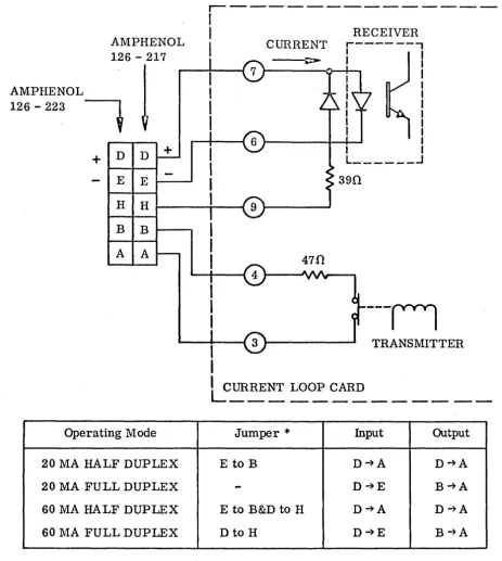
A Current Loop data interface may be ordered with the
VISTA BASIC. An AMPHENOL matrix connector is provided with
the unit. The connections for this interface are shown in
Figure 6.3.
#00744-Rev. B 18 February 1972
[image:44.617.52.546.152.771.2]-30-INFOTON INCORPORATED. SECOND AVENUE, BURLINGTON, MASSACHUSETIS 01803 • AREA CODE 617 272.6660
AMPHENOL 126 - 217
AMPHENOL
!
126 - 223
t
D D + +
E E
H H
B B
A A
Operating Mode
20 MA HALF DUPLEX
20 MA FULL DUPLEX
60 MA HALF DUPLEX
60 11A FULL DUPLEX
r---I
I
I
I
I
RECEIVER CURRENT
,---,
I I
I I
---~
~----~~+- I
I I
I
I I I
I
I L ______ -' I
390
---n
TRANSMITTERILCURRENT LOOP CARD
---
-Jumper
*
Input OutputE to B D~A D~A
-
D~E B~AE to B&D to H D~A D~A
Dto H D~E B~A
NOTE: Current must flow into positive terminal.
*
Jumper on mating connector Ampheno1126-223FIGURE 6.3
VISTA BASIC CURRENT LOOP CONNECTION
[image:45.617.70.533.59.576.2]