ISSN Print: 1942-0730
DOI: 10.4236/jemaa.2019.111001 Jan. 30, 2019 1 Journal of Electromagnetic Analysis and Applications
Synthesis and Optimization of Almost Periodic
Antennas Using Floquet Modal Analysis and
MoM-GEC Method
Nader Ben Latifa, Taoufik Aguili
Laboratory of the Communication Systems, National Engineering School of Tunis, Le Blvedere, Tunis, Tunisia
Abstract
This paper presented a new Floquet analysis used to calculate the radiation for 1-D and 2-D coupled periodic antenna systems. In this way, an accurate evaluation of mutual coupling can be proven by using a new mutual interac-tion expression that was based on Fourier analysis. Then, this work indicated how Floquet analysis can be used to study a finite array with uniform ampli-tude and linear phase distribution in both x and y directions. To modelize the proposed structures, two formulations were given in a spectral and spatial domain, where the Moment (MoM) method combined with a generalized equivalent circuit (GEC) method was applied. Radiation pattern of coupled periodic antenna was shown by varying many parameters, such as frequen-cies, distance and Floquet states. The 3-D radiation beam of the coupled an-tenna array was analyzed and compared in several steering angles θs and coupling values dx. The simulation of this structure demonstrated that di-rectivity decreased at higher coupling values. The secondary lobs in the an-tenna radiation pattern affected the main lobe gain by energy dispersal and considerable increasing of side lobe level (SLL) may be achieved. Therefore, the sweeping of the radiation beam in several steering directions affected the electromagnetic performance of the antenna system: the directivity at the steering angle θ =s π3 was more damaged and had 19.99 dB while the
second at θ =s 0 had about 35.11 dB. This parametric study of coupled
struc-ture used to concept smart periodic antenna with sweeping radiation beam.
Keywords
Periodic Antennas, Floquet Theory, Moment Method, GEC Method
1. Introduction
From the early days of communication systems, antenna arrays have been
wide-How to cite this paper: Latifa, N.B. and Aguili, T. (2019) Synthesis and Optimiza-tion of Almost Periodic Antennas Using Floquet Modal Analysis and MoM-GEC Method. Journal of Electromagnetic Analy-sis and Applications, 11, 1-16.
https://doi.org/10.4236/jemaa.2019.111001
Received: December 29, 2018 Accepted: January 27, 2019 Published: January 30, 2019 Copyright © 2019 by author(s) and Scientific Research Publishing Inc. This work is licensed under the Creative Commons Attribution International License (CC BY 4.0).
DOI: 10.4236/jemaa.2019.111001 2 Journal of Electromagnetic Analysis and Applications
spread. They are used in base stations, mobile phones and radars. They are made by elementary antennas combined together to synthesize a radiation pattern with a directional beam. There are several conventional methods applied to ana-lyze these systems in [1] [2] [3]. The coupling between the radiating elements increases with the dimension of the antenna arrays, making it one of the most important factors in the choice of the analysis method. Similar examples are found in [4]. In this context, the robustness of such method is evaluated by its resistance in front of the interaction between the radiating elements. In this work, we present a new formulation of the MoM-CEG method based on the Floquet theorem, (refer to [5] [6] [7] for details). This Floquet approach shows that the electromagnetic field distribution in periodic structures changes only by multiplication of a complex constant for a translation by one period in the global structure. The electromagnetic compilation of antenna arrays with an N pattern is then reduced to a calculation on one reference cell with periodic walls in a new modal base. Indeed, the term of phase shift contains itself the electromagnetic information of other adjacent cells. These artificial walls are implemented to group all phases from the periodic structure [8] [9] [10] [11]. Then, the Floquet modal analysis brings back all possible space calculations to new model calcula-tion. Then, the Floquet modal analysis examines all the Floquet states and the coupling information of the overall structure. This new method is applied to generate a 3-D electronically controlled antenna. The sweeping of the radiation beam of smart antennas is nowadays used to improve the performance of mobile and wireless communications systems [12] [13]. A number of works have been reported taking different periodic structures with spectral formulation to study 1-D and 2-D periodic antenna array [14][15] [16] [17]. But this work presents a new formulation of the MoM-CEG method based on Floquet theorem to optim-ize coupled periodic antenna with sweeping radiation beam.
This paper is organized as follows: First it is necessary to explain how to use Floquet modal analysis to decrease the complexity of periodic 1-D and 2-D structures, see e.g. [14]-[19]. Next, we present the numerical results and discuss the behavior of a 3-D steerable radiation beam and how to concept smart peri-odic antenna with sweeping beam with optimal performance.
2. Problem Formulation: Periodic Antenna Array
2.1. Formulation of 1D Periodic Antenna Array
In this section the formulation of the problem is illustrated in detail. A Floquet theory is proposed to reduce the infinite domain to a single cell with periodic walls. An electrical field is then formulated and solved through a MoM-GEC
[20] [21] approach in a spectral domain [22] [23] [24] [25]. The structure under analysis is shown in Figure 1. The excitation is given by an E0 voltage source
placed in the middle of a metallic patch. The width and the length of patches are w and l. The spatial period along the x direction is dx. The height of dielectric substance is h, and its relative permittivity εr is mounted on aground plane.
DOI: 10.4236/jemaa.2019.111001 3 Journal of Electromagnetic Analysis and Applications Figure 1. 1-D periodic antenna arrays presentation with Floquet theory.
Floquet theorem can be used with this geometric periodicity, so the study of global structure is reduced to one cell with Floquet phases exp
(
j Ndα
x)
. For details, see [2] [3] [10] [26] [27]. E x( )
represents an electric field reacting with this periodicity.(
)
(
) ( )
(
)
(
) ( )
(
)
(
) ( )
exp
2 exp 2
exp
x x
x x
x x
E x d j d E x
E x d j d E x
E x Nd j Nd E x
α α α + = ∗ + = ∗ + = ∗ (1)
Each Floquet phase corresponds to a Floquet state, and the function Fαm characterizes all possible states.
(
)
1 exp exp 2
m
x x
mx
F j x j
d d
α α
Π
= ∗
(2) where
α
and m correspond respectively to Floquet mode and spectral domain mode. Theα
values are in Brillouin domain ,x x
d d
−Π Π
. And for N discrete values of
α
, αp are given by:2
p Lp
α = Π (3)
where 1
2 2
N p N
− ≤ ≤ − and
x L N d= ∗ .
The electric field of the central cell in spacial domain is Em. We associate the electric field Eα in spectral domain, which models all waves emitted from oth-er cells of poth-eriodic structure.
(
)
1 exp
m m x
E + =E j dα (4) Then
(
)
exp d
2 xx
d x
m x
d
d
E Eα j mdα α
Π
Π
= Π
∫
(5)
DOI: 10.4236/jemaa.2019.111001 4 Journal of Electromagnetic Analysis and Applications
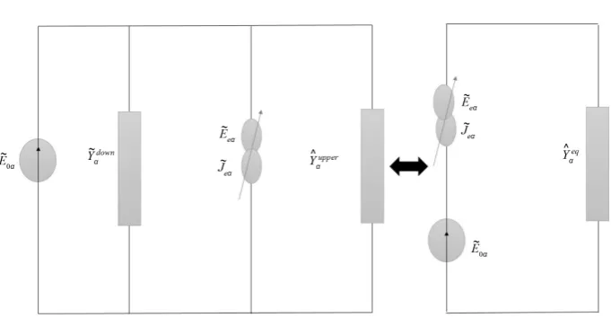
problem of the use an electric field integral equation can be solved by applying the GEC method. It can replace the integral equation by a simple equivalent cir-cuit in the discontinuity surface and applies the laws of tension and current to extract the relation between electric and current field by using an admittance operator [2] [3] [14] [15]. The discontinuity surface contains metallic and di-electric parties. The equivalent circuit of the unit cell is shown in Figure 2. The virtual electric field is defined on the metallic surface and is null on the dielec-tric part. We note that Eeα its dual. Similar examples are found in [28] [29]
[30].
From this circuit, we can deduce this system:
0 ˆ1
e
e eq e
J J
E E J
Y
α α
α α α
α = = − + ∗
(6)
The equivalent admittance operator is:
ˆeq ˆupper ˆdown
Yα =Yα +Yα (7)
ˆupper
Yα is the upper admittance operator of the infinite empty wave guide with periodic walls, and Yαˆdown is the down admittance operator of the short cir-cuited dielectric wave guide of height h with periodic walls.
ˆupper upper mn mn mn mn
Yα =
∑
f y α f (8)ˆdown down
mn mn mn mn
Yα =
∑
f y α f (9)mn
f are the base propagation mode functions.
Next, we apply the Galerkin method, where we project the excitation mode mn
f and the test function gpq on the previous equation. We then have the following system:
0 2 0 0
1
1 0 1 1 1
2
2 0
1 0
0 , ,
, , ,
0
0 ,
0 , , ,
n
eq
n
n n eq n
f g f g V
I
g f g Y g x
x g f
x
g f g Y g
α α α − − = (10)
The matrix form of the former equation can be developed as following:
0 0 0
0
t t
I A V
X
A B
α α
=
−
(11) where A is the excitation vector and B is the coupling matrix. The test courant functions in metallic part are gpq.
The resolution of the previous system consequently helps to calculate the vir-tual electric field Eeα and the electric far field ERad of the coupled structure.
2.2. Formulation 2-D Periodic Antenna Arrays
DOI: 10.4236/jemaa.2019.111001 5 Journal of Electromagnetic Analysis and Applications Figure 2. Equivalent circuit in spectral domain with MoM-CEM method of unit cell.
the x-axis and dy periodicity along the y-axis in Figure 3. Floquet theorem can be applied to synthesize periodic structures where all antenna elements are coupled with each other [16] [17] [31].
The formulation of the MoM-CEM method is applied to this reference cell with periodic walls in modal space, and the distribution of magnetic field differs only by two phases
(
α β
,)
compared to other cells. We pose Ji j, the source field in( )
i j, base cell in periodic device. In this new modal base, Jα β, is theset of excitation of the others cells such as:
(
)
(
)
(
)
(
)
1, 1 ,
1, ,
, 1 ,
exp exp
exp ,
exp
i j i j x y
i j i j x
i j i j y
J J i d i d
J J i d i j
J J i d
α
β
α
β
+ ++
+
=
= ∀
=
(12)
Floquet modal analysis reduces spacial electromagnetic calculus of 2-D peri-odic structure to a spectral calculus in a new modal base which gathers all possi-ble phases in periodic walls. In this case, we consider the 2-D dimensional case along the x- and y-axis with
(
N N∗)
identical cells, where each one is excited by a located source. The two phasesα
andβ
belong respectively to theBrillouin domain: ,
x x
d d
−Π Π
and dy ,dy −Π Π
. The discretization of Floquet mode provides the following: α =2πp L and β =2πq L, where p and q are two integer and L N d= ∗ . From these Floquet phases, we associate two fields
Eαβ and Jαβ which model all waves emitted from others cells of the periodic structure.
The discontinuity surface contains metallic and dielectric parties. The excita-tion Eαβ of the central path produces a current field Jαβ. This virtual mag-netic field Jeαβ is defined on the metallic surface and is null on the dielectric part. We note that Eeαβ is its dual. The electric field Jmn can be developed as following:
(
)
(
)
π π
π π
2π d d exp exp d d
mn d d
DOI: 10.4236/jemaa.2019.111001 6 Journal of Electromagnetic Analysis and Applications Figure 3. 2-D periodic antenna arrays presentation with Floquet theory.
which d 2π is a normalization factor and dx =dy =d . Based on the MoM-CEM method and using the laws of tension and current of the equivalent circuit, we can extract and identify the relationship between the current density, the electric field and admittance operator Yˆeq
αβ.
From this equivalent circuit, we can deduce the following system:
0 ˆ1
e
e eq e
J J
E E J
Y
αβ αβ
αβ αβ αβ
αβ
=
= − + ∗
(14)
Then
0
0 1
1 1 ˆ
e eq e
J E
E J
Y
αβ αβ
αβ αβ
αβ
=
−
(15)
The equivalent admittance operator is:
ˆeq ˆdown ˆupper
Yαβ =Yαβ +Yαβ (16)
ˆupper
Yαβ and Yˆαβdown are respectively the upper and the down admittance oper-ator.
where:
ˆupper upper mn mn mn mn
Yαβ =
∑
f y αβ f (17)ˆdown down
mn mn mn mn
Yαβ =
∑
f y αβ f (18)mn
f are the base propagation mode functions.
DOI: 10.4236/jemaa.2019.111001 7 Journal of Electromagnetic Analysis and Applications
(
fmn g, pq)
and can be developed as the following:0 2 0
0 1
1 0 1 1 1
2
2 0
1 0
0 , ,
, , ,
0
0 ,
0 , , ,
n
eq
n
n n eq n
f g f g V
I
g f g Y g x
x g f
x
g f g Y g
αβ αβ αβ − − = (19)
So, we can deduce the following system:
0 0 0
0
t t
I A V
X
A B
αβ αβ
=
−
(20) where A is the excitation vector and B is the coupling matrix.
3. Results and Observations
3.1
.
Studie of FloquetStates
In this section, we present a Floquet modal analysis of periodic antenna array. As an example we simulate and design a structure of four linear elements using matlab software. We extract all possible Floquet modes
(
α β
,)
; and we showtheir influence on pattern radiation. Results are presented for the following pa-rameters: ε =r 1, h=5.5 mm, dx =108 mm, dy =54 mm, l=27 mm, w=1 and δ =0.75 mm.
[image:7.595.204.539.76.221.2]The behavior of magnetic field for one reference cell is shown in Figure 4.
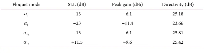
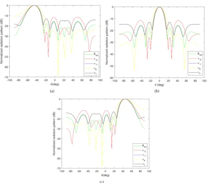
Table 1 illustrates the performance parameter (side lobe level, peak gain and di-rectivity) of radiation pattern for each Floquet mode. Refer to [32] [33] [34] for details. The radiation pattern plot in Figure 5 obtained by using Floquet modal method demonstrates the aptitude of this technique to superpose all Floquet modes
(
α α α α
−2, −1, ,0 1)
and their superposition Etot for different steering an-gles θs [35] [36].The electromagnetic parameters of each Floquet mode
(
α α α α
−2, −1, ,0 1)
ofthis periodic structure are compared in Table 1. The simulation of this periodic structure demonstrates that each Floquet mode defines the mutual coupling of the adjacent cell. The superposition of all Floquet modes represents the evolu-tion of pattern radiaevolu-tion of the reference cell coupled with all others cells.
3.2
.
Frequency andCoupling Effect
[image:7.595.208.540.648.737.2]In this section, we present and briefly discuss several results of the radiation pat-tern on an open structure analyzed in the previous section. The simulated radiation
Table 1. Performance Parameters of the 1-D periodic structure for each Floquet mode.
Floquet mode SLL (dB) Peak gain (dBi) Directivity (dB)
1
α −13 −6.1 25.18
0
α −23 −11.4 23.66
1
α− −13 −6.1 25.81
2
DOI: 10.4236/jemaa.2019.111001 8 Journal of Electromagnetic Analysis and Applications Figure 4. 2-D representation of the current density J Jmax with the basis functions at
5.4 Ghz
F= , h=1.25 mm , dx=108 mm, dy=54 mm , w=1 mm , =1, r=1, 0.75 mm
δ= , λ=54 mm, α=0 rad m⋅ −1, β=0 rad m⋅ −1.
(a) (b)
(c)
Figure 5. Simulated 2-D normalized radiation pattern of periodic antenna for several steering angles θs using: 5.4 Ghz
F= , h=1.25 mm, dx=108 mm, dy=54 mm, w=1 mm, =1, r=1, δ=0.75 mm, λ=54 mm. (a) 45 deg
s
[image:8.595.115.539.301.673.2]DOI: 10.4236/jemaa.2019.111001 9 Journal of Electromagnetic Analysis and Applications
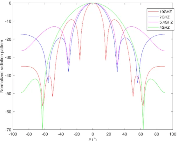
pattern of the antenna is shown in Figure 6. The electromagnetic near fields of the planner antenna were simulated with Floquet analysis combined with MoM-CEG method. From these results, the radiation pattern was calculated us-ing the conventional method of the stationary phase. It can be observed that the evolution of the pattern radiation for different values of the frequency from 4 to 10 GHz is not the same, but they have a similar behavior. By exploiting this fig-ure, at F = 4 GHz, a low directivity is achieved with high power Pmax (the power in decibel between the maximum of main lobe and the maximum of secondary lobs) with 40 dB and at 10 GHz, a high directivity is achieved with low power Pmax with 10 dB. We deduce then that the diagram becomes increasingly selec-tive by increasing the frequency, but at the same time, the amplitude of the sec-ondary lobes increases.
Figure 7 shows the influence of coupling value on radiation pattern in rela-tion to wavelength. For dx =λ, the power Pmax is 30 dB, but for dx =3λ, the power Pmax is 10 dB. From these results, we can deduce that the pattern radia-tion of this structure becomes more directive when the period dx increases compared to wavelength λ.
[image:9.595.221.526.429.672.2]In this example, on 1-D periodic array four planar antennas is discussed. The amplitude of each excitation and the phase difference of neighboring cell are identicals. The radiation simulation shown in Figure 6 and Figure 7 reveals that the behavior of radiation pattern is acceptable with MoM-GEC method com-bined to Floquet theory and large separation between elements is needed for high directivity.
Figure 6. The normalized radiation pattern in value (dB) against several frequencies F using: h=1.25 mm , dx=54 mm , dy=54 mm , w=1 mm , =1 , r=1 ,
0.75 mm
DOI: 10.4236/jemaa.2019.111001 10 Journal of Electromagnetic Analysis and Applications Figure 7. The normalized radiation pattern value in (dB) against several periods dx of global structure using: F=5.4 Ghz, h=1.25 mm , dy=54 mm, w=1 mm, =1,
1
r=
, δ=0.75 mm, λ=54 mm, α=0 rad m⋅ −1, β=0 rad m⋅ −1.
4. 3-D radiation of Smart Periodic Antenna
4.1
.
CouplingEffect
In this section, we study the influence of the coupling and the steering direction on the electromagnetic parameters of our periodic structure.
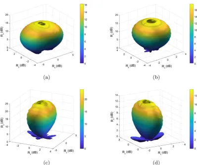
Figure 8 shows a 3-D beam radiation of the coupled structure in the steered
direction θ =s 0 for different coupling states dx =λ,dx=2 ,λ dx=3 ,λ dx =4λ. Electromagnetic performance parameters of this coupled structure in different coupling values are shown in Table 2.
4.2
.
SteeringDirections Effect
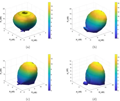
Figure 9 shows a 3-D beam radiation of the coupled structure in the high coupling value
(
dx =2λ
)
for different steering directions:0, 6, 4, 3
s s s s
θ = θ = Π θ = Π θ = Π .
Electromagnetic performance parameters of this coupled structure in different steered directions θs are shown in Table 3 for high and low coupling values.
DOI: 10.4236/jemaa.2019.111001 11 Journal of Electromagnetic Analysis and Applications Figure 8. The 3-D radiation beam pattern of proposed antenna array at different coupling states for steered angle θs=0 using: F=10.4 Ghz, h=1.25 mm, dy=54 mm, w=1 mm, =1, r=1, δ=0.75 mm,
28 mm
[image:11.595.208.540.498.580.2]λ= ; (a) dx=λ; (b) dx=2λ; (c) dx=3λ; (d) dx=4λ.
Table 2. The Performance Parameters for Different Coupling Values dx of the 1-D periodic structure.
Periodicity dx Directivity (dB)
λ 29.48
2λ 30.38
3λ 35.11
4λ 39.99
Table 3. The performance parameters for different steering directions θs in in low and high coupling values of 1-D periodic structure.
Steering angle θs
Directivity (dB) low coupling
(dx=4λ)
Directivity (dB) high coupling
(dx=λ)
0 39.99 29.48
6
Π 28.10 20.41
4
Π 24.66 19.51
3
[image:11.595.209.540.629.734.2]DOI: 10.4236/jemaa.2019.111001 12 Journal of Electromagnetic Analysis and Applications Figure 9. The 3-D radiation beam pattern of proposed antenna array at different steering directions θs in high coupling values using: F=5.4 Ghz, λ=28 mm, h=1.25 mm, dx=2λ, dy=54 mm, w=1 mm,
1
=
, r=1, δ =0.75 mm; (a) θs=0, (b) θs= Π6, (c) θs= Π4, (d) θs= Π3.
the main lobe gain by energy dispersal and also disturbs the second radiant ele-ment. Therefore, a condition regarding the spacing of sources must be imposed.
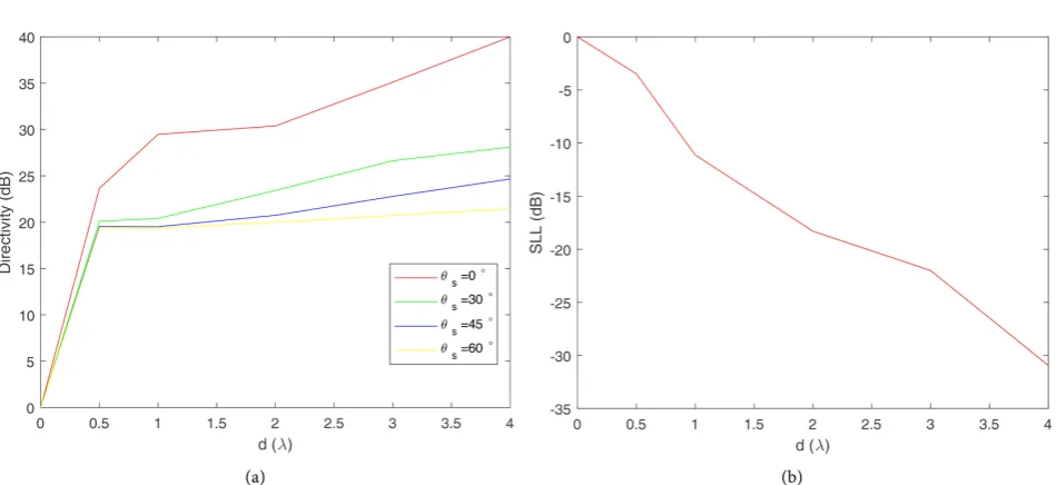
Figure 10 represents respectively the variation of the directivity and the side lobe level for several distances d and for several steering directions θs. For the working frequency F=10 GHz, the spacing d between the sources must exceed
2
λ
=56 mm to ensure a −18.3 dB of side lobe level. Also, for the same parame-ters, to obtain a directivity greater than 23.42 dB the steering angle must not ex-ceed pi/6. By exploiting Figure 10, we can concept a smart periodic antenna with minimal coupling and acceptable directivity. finally, we can deduce that high directivity values can be achieved with low sweeping angles θs, also low coupling values can be achieved with high spacing values d.5. Conclusion
DOI: 10.4236/jemaa.2019.111001 13 Journal of Electromagnetic Analysis and Applications Figure 10. Directivity and side lobe level evolution of proposed antenna array at different steering directions θs: F=10.4 Ghz,
1.25 mm
h= , dy=54 mm, w=1 mm, =1, r=1, δ=0.75 mm, λ=28 mm; (a) directivity in terms of λ, (b) SLL in terms of λ.
modes. To properly control the directivity of periodic antennas and minimize coupling between cells, it is necessary to choose the best period dx. This can be also useful for the analysis of 3-D beam radiation for different steering directions and coupling values. Then, we can concept a smart periodic antenna with mi-nimal coupling and acceptable directivity for different sweeping angles. For the special case when high coupling is presented, we can easily show that directivity is reduced to 19.37 dB when θ =s π 3, while the side lobe level is increased to
−11.12 dB. The essential advantage of this new modal analysis is concepting coupled periodic antenna with sweeping radiation beam. The numerical results demonstrate the feasibility of the proposed approach in the field of estimation side lobe level and directivity of almost periodic antenna. In conclusion, we would like to highlight that Floquet model analysis and MoM-GEC method are needed to study coupled smart antenna that opens various areas of research.
Conflicts of Interest
The authors declare no conflicts of interest regarding the publication of this paper.
References
[1] Baudrand, H., Titaouine, M., Raveu, N. and Fontgland, G. (2009) Electromagnetic Modeling of Planar almost Periodic Structures. SBMOI/IEEE MTT-S International Microwave and Optoelectronics Conference, Belem, 3-6 November 2009, 427-431.
https://doi.org/10.1109/IMOC.2009.5427552
DOI: 10.4236/jemaa.2019.111001 14 Journal of Electromagnetic Analysis and Applications
Leaky-Wave Antenna with Arbitrary Metallic Strips. Electromagnetic, 28, 296-314.
https://doi.org/10.1080/02726340802040161
[4] Xi, Y.P., Fang, D.G., Sun, Y.X. and Chow, Y.L. (2005) Mutual Coupling in a Linear Dipole Array of Finit Size. IEE Proceedings-Microwaves Antennas and Propagation, 152, 324-330.
[5] Massaro, A., Cingolani, A., Passasea, A. and Vittoriol, M. (2009) Floquet’s Unit Cell Deseign for Periodic Structures Atoptical Frequencies. International Journal of Mi-crowave Science and Technology, 2009, Article ID 160321.
https://doi.org/10.1155/2009/160321
[6] Bhattacharyya, K.A. (2012) Floquet Modal Based Analysis of Finite and Infinite Phased Array Antennas. Macquarie University and IEEE Joint Lecture.
[7] Arun Bhattacharyya, K. (2006) Phased Array Antennas. John Wiley and Sos, Inc. Publication, Hoboken.
[8] Makarov, S., Puzella, A. and Iyer, V. (2008) Scan Impedance for an Infinite Dipole Array: Accurate Theoretical Model Compared to Numerical Software. IEEE Anten-nas and Propagation Magazine, 50, 132-149.
https://doi.org/10.1109/MAP.2008.4768944
[9] Sze, K. and Shafai, L. (1999) Reflection Properties of Infinite Periodic Arrays of Rectangular Conducting Patches. Canadian Journal of Electrical and Computer En-gineering, 24, 35-41.
[10] Watanable, K. and Yasumoto, K. (2007) Tow-Dimensional Electromagnetic Scat-tering of Non-Plane Incident Waves by Periodic Structures. Progress in Electro-magnetics Research, 74, 241-271. https://doi.org/10.2528/PIER07050902
[11] Skrivervik, K. and Mosig, L. (1992) Finite Phased Array of Microstrip Patch Anten-nas: The Infinite Array Approach. IEEE Transactions on Antennas and Propaga-tion, 40, 579-582.
[12] Reyanaa, A., Panduroa, D., Covarrubias and Mendeza, A. (2012) Design of Steerable Concentric Rings Array for Low Side Lobe Level. Scientia Iranica, 19, 727-732.
https://doi.org/10.1016/j.scient.2011.08.028
[13] Dauguet, S., Gillard, R., Citerne, J. and Piton, G. (1997) Extension of the Compres-sion Approach to Include the Treatement of Radiation Pattern in the Electromag-netic Analysis of Active Plannar Antennas. Antennas and Propagation Society In-ternational Symposium, 22-25.
[14] Bilel, H., Aguili, T. and Baugrand, H. (2015) Floquet Modal Analysis to Modelize and Study 2 D Planar almost Periodic Structures in Finite and Infinite Extend with Coupled Motifs. PIERS B.
[15] Bilel, H., Aguili, T., Ravue, N. and Baugrand, H. (2014) Calculation of Mutual Coupling Parameter and Their Effects in 1D almost Periodic Structures. PIERS B. [16] Bilel, H., Limam, S. and Aguili, T. (2016) Uniform and Concentric Circular
Anten-na Arrays Synthesis for Smart AntenAnten-na Systems Using Artificial Neural Network Algorithm. Progress in Electromagnetics Research B, 67, 91-105.
https://doi.org/10.2528/PIERB16031508
[17] Bilel, H., Aguili, T. and Audrand, H. (2012) Uni-Dimensional Planar Almost Peri-odic Structures Analysis to Decompose Central Arbitrary Located Source in Spec-tral Domain. International Symposium on Antenna Technology and Applied Elec-tromagnetics, Toulouse, 25-28 June 2012, 1-5.
DOI: 10.4236/jemaa.2019.111001 15 Journal of Electromagnetic Analysis and Applications
a Periodic Microstrip Line by an Aperiodic Delta-Gap Source. IEEE Transactions on Antennas and Propagation, 8, 641-644.
https://doi.org/10.1109/LAWP.2009.2023252
[19] Berry, D., Malech, R. and Kennedy, W. (2012) The Reflectarray Antenna. IEEE Transaction on Antennas and Propagation, 11, 645-651.
https://doi.org/10.1109/TAP.1963.1138112
[20] Riabi, M., Ahmadpanah, M., Benzina, H., Baudrand, H. and Fouad Hanna, V. (1995) Performance of the LSBRM Using Efficient Weighting Functions for Planar Structures. IEEE Transaction on Antennas and Propagation, 142, 364-368. https://doi.org/10.1049/ip-map:19952004
[21] Mili, S. and Aguili, T. (2011) Study of Fractal-Shaped Structures with Pin Diodes Using the Multi-Scale Method Combined to the Generalized Equivalen Circuit Modeling. Progress in Electromagnetics Research B, 27, 213-233.
https://doi.org/10.2528/PIERB10110105
[22] Montgomery, J. (1978) Scattering by an Infinite Periodic Array of Microstrip Ele-ments? IEEE Transaction on Antennas and Propagation, 26, 850-854.
https://doi.org/10.1109/TAP.1978.1141956
[23] Arrebola, M., Alvarez, Y., Encinar, J. and Las-Heras, F. (2009) Accurate Analysis of Printed Reflectarrays Considering the near Field of the Primary Feed. IET Micro-waves, Antennas and Propagation, 3, 187-194.
https://doi.org/10.1049/iet-map:20070325
[24] Hannan, P. and Balfour, M. (1965) Simulation of a Phased Array Antenna in Wa-veguide. IEEE Transaction on Antennas and Propagation, 13, 342-353.
https://doi.org/10.1109/TAP.1965.1138428
[25] Milon, M., Cadoret, D., Gillard, R. and Legay, H. (2007) Surrounded-Element Ap-proach for the Simulation of Reflectarray Radiating Cells. IET Microwaves Anten-nas and Propagation, 1, 289-293.https://doi.org/10.1049/iet-map:20050291
[26] Aguili, T. (2000) Thesis Modélisation des composants SHF planaires par la mthode-circuits equivalents. National Engineering Scool of Tunis ENIT.
[27] Aubert, H. and Baudrant, H. (2003) Lelectromagnetisme par les Schemas Equiva-lents. Cepadus.
[28] Raveu, N. and Pigaglio, O. (2012) Rsolution de problemes hautes frquences par les schmas quivalents. ditions Cpadues.
[29] Clement, Y. (2012) Thesis Modlisation lectromagntique de cellules actives envi-ronnes-Application a l’analyse et la synthese d’une antenne reflectarray a balayage lecronique. INSA de Rennes.
[30] Jihed, B.S. (2013) Rductibilit et thorie de Floquet pour systemes diffrenciels non li-naires. Universit Panthon-Sorbone, Paris.
[31] Nosal, S. (2009) Modlisation lectromagntique de structures priodiques et matriaux artificiels Application a la conception d’un radome passe bande. cole centrale Paris. [32] Reynaa, A., Panduroa, A. and Covarrubias, H. (2012) Design of Steerable
Concen-tric Rings Array for Low Side Lobe Level. Scientia Iranica, 19, 727-732. https://doi.org/10.1016/j.scient.2011.08.028
DOI: 10.4236/jemaa.2019.111001 16 Journal of Electromagnetic Analysis and Applications
[34] Ben Latifa, N., Bilel, H. and Aguili, T. (2017) Floque Modal Analysis to Study Peri-odic and AperiPeri-odic Planar Antenne Arrays with Mututal Coupling.
[35] Ben Latifa, N., Bilel, H. and Aguili, T. (2018) Electronically Steerable Radiation Pat-tern of Coupled Periodic Antenna Used Floquet Analysis.