423042 TDC 4000 Series SCSI 2 Interface Functional Specifications May97 pdf
310
0
0
Full text
(2) SCSI-2 Firmware Information: This documentation supports SCSI-2 Firmware version 8.06. Related publications available from our Sales & Marketing Department: Publ. No.. Part No.. Title. 6046. 42 30 40. 9048. 43 05 08. TDC 4000 Series SCSI-1 Interface - Functional Specifications SLR (TDC 4000) Series Reference Manual. This publication may describe designs for which patents are granted or pending. By publishing this information, Tandberg Data ASA conveys no license under any patent or any other rights. Every effort has been made to avoid errors in text and diagrams. However, Tandberg Data ASA assumes no responsibility for any errors which may appear in this publication. It is the policy of Tandberg Data ASA to improve products as new techniques and components become available. Tandberg Data ASA therefore reserves the right to change specifications at any time. We would appreciate any comments on this publication..
(3) ___________________________________________________________________. Table of Contents - SCSI-2 1. 1.1. 1.2. 1.3. 1.4. 1.5.. Introduction General Purpose of this Document Overview Glossary Additional Reference Documentation. 1-1 1 2 2 3 5. 2. 2.1. 2.2. 2.3. 2.4. 2.4.1. 2.4.2. 2.4.3. 2.4.4. 2.5. 2.6. 2.6.1. 2.6.2. 2.6.3. 2.6.4. 2.6.4.1. 2.6.4.2. 2.7. 2.7.1. 2.7.2. 2.7.3. 2.7.4. 2.7.5. 2.7.6. 2.7.7. 2.7.8. 2.7.9. 2.7.10. 2.7.11. 2.8. 2.9.. About Tape Streamers Physical Elements Data Storage Characteristics Partitions Within a Volume Quick File Access Setting the QFA-mode Changing Partitions Before Reading Changing Partitions Before Writing General QFA-rules on Write Logical Elements Within a Partition Using Fixed and Variable Length Blocks Variable and Fixed Length Blocks Writing Reading Illegal Length Conditions when Reading Reading with the Fixed-Bit Clear Reading with the Fixed-Bit Set Data Buffering Introduction Blocks Blocking/De-blocking Buffered Mode Read-Ahead Underrun/Overrun Buffer Thresholds Deadlock Prevention - Read Disconnect/Re-connect Data Re-transfer Buffer Parity Errors Recorded Objects SLR5 4.0/8.0GB and SLR4 2.5/5.0GB (TDC 4222) Only - Data Compression. 2-1 1 1 2 3 4 4 5 6 7 8 8 8 9 9 9 10 11 11 11 12 13 13 14 14 16 17 18 19 19. Logical Characteristics SCSI-bus Phases Bus Free Phase Arbitration Phase Selection Phase Reselection Phase Information Transfer Phases Command Phase Data In/Out Phases Status Phase Message-In/Out Phases Signal Restrictions between Phases SCSI-bus Conditions Attention (ATN). 3-1 1 1 2 2 2 3 3 3 3 4 4 5 5. 3. 3.1. 3.1.1. 3.1.2. 3.1.3. 3.1.4. 3.1.5. 3.1.5.1. 3.1.5.2. 3.1.5.3. 3.1.5.4. 3.1.6. 3.2. 3.2.1. i. 20. SCSI-2 Functional Specifications.
(4) Tandberg Data Table of Contents - SCSI-2 ___________________________________________________________________ 3.2.1.1. 3.2.1.2. 3.2.2. 3.2.2.1. 3.2.2.2. 3.3. 3.4. 3.5. 3.5.1. 3.5.1.1. 3.5.1.2. 3.5.1.3. 3.5.1.4. 3.5.2.. The Drive as a Target The Drive as an Initiator Reset The Drive as a Target The Drive as an Initiator Unit Attention SCSI Pointers SCSI-bus Phase Sequences The Drive as a Target Notation Legal Sequences Disconnects/Reconnects Command Linking The Drive as an Initiator. 5 6 7 7 7 8 9 10 11 11 12 15 28 29. 4. 4.1. 4.2. 4.3. 4.4. 4.5. 4.5.1. 4.5.2. 4.6. 4.6.1. 4.6.2. 4.6.3.. Commands The Command Descriptor Block Command Control Byte Reserved Fields Command Set Summary Command Sequencing Normal Modes Exception Modes Overlapped Command Handling Background The Drive is Selected by the Same Initiator The Drive is Selected by Another Initiator. 4-1 1 2 2 3 5 5 8 12 12 12 13. 5.. Status Bytes. 5-1. 6. 6.1. 6.2. 6.3. 6.3.1. 6.4. 6.5.. Message System Message-In Message-Out Extended Message Synchronous Data Transfer Request Message Message Reject Message Handling Abort Message Handling. 6-1 1 3 5 5 7 8. 7. 7.1. 7.2. 7.3. 7.4. 7.5. 7.6. 7.6.1. 7.6.1.1. 7.6.1.2. 7.6.2. 7.6.2.1. 7.6.2.2. 7.7. 7.8.. General Exception Handling Error Codes Error Conditions for All Commands Deferred Errors Error Conditions for Media Access Commands Recovered Errors Bus Parity Error Handling The Drive as a Target Errors Detected by the Drive Errors Detected by the Initiator The Drive as an Initiator Errors Detected by the Drive Errors Detected by the Target Buffer Parity Error Handling Error Priority. 7-1 1 6 7 8 9 10 10 10 11 11 11 12 13 13. 8. 8.1. 8.2.. Copy Command Description Copy Command Descriptor Block. 8-1 1 3. ii. SCSI-2 Functional Specifications.
(5) Tandberg Data Table of Contents - SCSI-2 ___________________________________________________________________ 8.3. 8.3.1. 8.3.2. 8.4. 8.4.1. 8.4.2. 8.4.3. 8.5. 8.5.1. 8.5.2. 8.6. 8.6.1. 8.6.2. 8.6.3. 8.6.4. 8.6.5. 8.6.6. 8.7. 8.7.1. 8.7.1.1. 8.7.2. 8.8.. Parameter List Header List Segment Descriptor List Selectable Options Buffered Mode Copy Threshold Copy Sense Allocation Block Sizes Checking the Block Size Inexact Segments Commands Used as an Initiator Read (6-byte Command) Read (10-byte Command) Read Capacity Request Sense Write (6-byte Command) Write (10-byte Command) Exception Handling Management Errors Inexact Segment Errors Data Transfer Errors Internally Generated Sense Bytes. 4 4 5 6 6 6 7 7 7 8 9 9 10 11 11 12 13 13 14 16 16 19. 9. 9.1. 9.2. 9.3.. Erase Command Description Command Descriptor Block Exception Handling. 10. 10.1. 10.2. 10.3. 10.3.1. 10.3.2. 10.3.2.1. 10.3.2.2. 10.3.2.3. 10.3.2.4. 10.3.2.5. 10.3.2.6. 10.3.2.7. 10.3.2.8. 10.3.2.9. 10.4.. Inquiry Command Description Command Descriptor Block Parameter Lists Standard Inquiry Data Vital Product Data Summary of Supported Pages Unit Serial Number Implemented Operating Definitions ASCII Implemented Operating Definition Hardware Revision Levels ROM Software Code Revision Level Drive Manufacturing Date ROM Software Creation Date Drive Adjustment Date Exception Handling. 10-1 1 1 3 3 7 7 8 9 10 12 13 14 15 16 17. 11. 11.1. 11.2. 11.3.. Load/Unload Command Description Command Descriptor Block Exception Handling. 11-1 1 2 3. 12. 12.1. 12.2. 12.3.. Locate Command Description Command Descriptor Block Exception Handling. 12-1 1 2 3. 13. 13.1.. Log Select Command Description. 13-1 1. iii. 9-1 1 1 2. SCSI-2 Functional Specifications.
(6) Tandberg Data Table of Contents - SCSI-2 ___________________________________________________________________ 13.2. 13.3. 13.3.1. 13.3.2. 13.3.3. 13.3.4. 13.3.5. 13.3.6. 13.4.. Command Descriptor Block Parameter List General Parameter Description Buffer Over/Underrun Counter Page Recoverable Write Error Counter Page Recoverable Read Error Counter Page Block Counter Page Filemark Counter Page Exception Handling. 1 2 2 2 3 3 3 4 4. 14. 14.1. 14.2. 14.3. 14.3.1. 14.3.2. 14.3.3. 14.3.4. 14.3.5. 14.3.6. 14.3.7. 14.3.8. 14.4.. Log Sense Command Description Command Descriptor Block Parameter List Supported Log Pages Buffer Overrun/Underrun Counters Page Recoverable Write Error Counter Page Recoverable Read Error Counters Page Block Counter Page Tape Capacity Page Filemark Counter Page Physical Position Page Exception Handling. 14-1 1 1 3 3 4 7 8 11 12 14 15 17. 15. 15.1. 15.2. 15.3. 15.3.1. 15.3.2. 15.3.3. 15.3.4. 15.3.5.. Mode Select Command Description Command Descriptor Block Parameter List Header List Block Descriptor List Error Recovery Page Disconnect/Reconnect Page SLR5 4.0/8.0GB and SLR4 2.5/5.0GB (TDC 4222) Only - Data Compression Parameters Page Device Configuration Parameters Page Medium Partition Parameters Page Miscellaneous Parameters Page User Page 0 User Page 1 Exception Handling. 15-1 1 2 3 3 4 7 9. Mode Sense Command Description Command Descriptor Block Parameter List Header List Block Descriptor List Error Recovery Page Descriptor Disconnect/Reconnect Page Descriptor SLR5 4.0/8.0GB and SLR4 2.5/5.0GB (TDC 4222) Only - Data Compression Page Descriptor Device Configuration Parameters Page Descriptor Medium Partition Parameters Page Descriptor Miscellaneous Parameters Page Descriptor User Page 0 Page Descriptor User Page 1 Page Descriptor Exception Handling. 16-1 1 3 4 4 6 7 7. 15.3.6. 15.3.7. 15.3.8. 15.3.9. 15.3.10. 15.4. 16. 16.1. 16.2. 16.3. 16.3.1. 16.3.2. 16.3.3. 16.3.4. 16.3.5. 16.3.6. 16.3.7. 16.3.8. 16.3.9. 16.3.10. 16.4. iv. 12 14 17 18 26 27 27. 8 8 9 9 10 10 10. SCSI-2 Functional Specifications.
(7) Tandberg Data Table of Contents - SCSI-2 ___________________________________________________________________ 17. 17.1. 17.2. 17.3.. Prevent/Allow Medium Removal Command Description Command Descriptor Block Exception Handling. 17-1 1 1 1. 18. 18.1. 18.2. 18.3. 18.3.1. 18.3.2. 18.3.3. 18.3.4. 18.3.4.1. 18.3.4.2. 18.3.5. 18.3.6. 18.3.7. 18.3.7.1. 18.3.7.2. 18.3.8. 18.3.9.. Read Command Description Command Descriptor Block Exception Handling General No Data Filemark Detected Illegal Length FIX Bit Set to ZERO FIX Bit Set to ONE Logical End of Partition Physical End of Partition Non-Recoverable Read Error Fixed Blocks Variable Blocks Illegal Termination SLR5 4.0/8.0GB and SLR4 2.5/5.0GB (TDC 4222) Only - Data Compression Exception Handling SLR5 4.0/8.0GB and SLR4 2.5/5.0GB (TDC 4222) Only - Reading From the Beginning of the Directory Partition. 18-1 1 2 3 3 3 3 4 4 4 5 5 6 6 7 8. 19. 19.1. 19.2. 19.3. 19.4.. Read Block Limits Command Description Command Descriptor Block Parameter List Exception Handling. 19-1 1 1 1 2. 20. 20.1. 20.2. 20.3. 20.3.1. 20.3.2. 20.4. 20.4.1. 20.4.2. 20.4.3. 20.4.4. 20.4.5. 20.4.6. 20.4.7. 20.5. 20.6.. Read Buffer Command Description Command Descriptor Block Read Combined Header and Data Mode (000b) Header List Data List Read Data Mode (010b) Data Buffer (Buffer ID = 0) CPU Memory (Buffer ID = 1) Hardware Registers (Buffer ID = 2) Internal RAM (Buffer ID = 3) EEPROM (Buffer ID = 4) External RAM (Buffer ID = 5) Microcode Store (Buffer ID = 6) Read Descriptor Mode (011b) Exception Handling. 20-1 1 1 3 3 3 3 3 4 4 4 4 5 5 5 6. 21. 21.1. 21.2. 21.3. 21.4.. Read Position Command Description Command Descriptor Block Parameter List Exception Handling. 21-1 1 2 3 5. 18.3.10.. v. 8. 9. SCSI-2 Functional Specifications.
(8) Tandberg Data Table of Contents - SCSI-2 ___________________________________________________________________ 22. 22.1. 22.2. 22.3. 22.3.1. 22.3.2. 22.3.3. 22.3.4. 22.3.4.1. 22.3.4.2. 22.3.5.. Recover Buffered Data Command Description Command Descriptor Block Exception Handling General Command Sequencing Filemark Detected Illegal Length FIX Bit Set to ZERO FIX Bit Set to ONE End of Buffer. 22-1 1 1 2 2 2 3 3 3 3 4. 23. 23.1. 23.2. 23.3.. Release Unit Command Description Command Descriptor Block Exception Handling. 23-1 1 1 2. 24. 24.1. 24.2. 24.3. 24.4. 24.5. 24.6.. Request Sense Command Description Command Descriptor Block Parameter List Sense Keys Additional Sense Code and Qualifier Exception Handling. 24-1 1 1 2 7 8 10. 25. 25.1. 25.2. 25.3.. Reserve Unit Command Description Command Descriptor Block Exception Handling. 25-1 1 2 2. 26. 26.1. 26.2. 26.3.. Rewind Command Description Command Descriptor Block Exception Handling. 26-1 1 1 1. 27. 27.1. 27.2. 27.3. 27.4. 27.5. 27.6. 27.7.. Send Diagnostics Command Description Command Descriptor Block Parameter List Default Test Parameters Selftest 1 Selftest 2 Exception Handling. 27-1 1 2 3 4 4 5 6. 28. 28.1. 28.2. 28.3. 28.4. 28.4.1. 28.4.2. 28.4.3. 28.4.4. 28.4.5. 28.4.6. 28.4.7.. Space Command Description Command Descriptor Block Using Fast Space Exception Handling General No Data Filemark/Setmark Detected Logical End of Partition Physical Beginning of Partition Physical End of Partition Non-Recoverable Read Error During Space Forward. 28-1 1 2 2 3 3 3 4 4 4 4. vi. 5. SCSI-2 Functional Specifications.
(9) Tandberg Data Table of Contents - SCSI-2 ___________________________________________________________________ 28.4.8. 28.4.9.. Error Condition or Bad Block During Space Reverse SLR5 4.0/8.0GB and SLR4 2.5/5.0GB (TDC 4222) Only - Exception Handling. 5 5. 29. 29.1. 29.2. 29.3.. Test Unit Ready Command Description Command Descriptor Block Exception Handling. 29-1 1 1 1. 30. 30.1. 30.2. 30.3. 30.3.1.. Verify Command Description Command Descriptor Block Exception Handling SLR5 4.0/8.0GB and SLR4 2.5/5.0GB (TDC 4222) Only - Exception Handling. 30-1 1 2 3. Write Command Description Command Descriptor Block Terminating Write Operations Write from BOM Exception Handling General Illegal Media Type Illegal Append Tape Format Pseudo Early Warning End of Partition Non-Recoverable Write Error Append Error SLR5 4.0/8.0GB and SLR4 2.5/5.0GB (TDC 4222) Only - Data Compression Exception Handling SLR5 4.0/8.0GB and SLR4 2.5/5.0GB (TDC 4222) Only - Writing From the Beginning of the Directory Partition. 31-1 1 3 3 4 5 5 5 6 6 7 7 8. 32. 32.1. 32.2. 32.3. 32.4. 32.5. 32.6. 32.7. 32.8.. Write Buffer Command Description Command Descriptor Block Combined Header and Data Mode (000b) Write Data Mode (010b) Download Microcode Mode (100b) Download Microcode and Save Mode (101b) Microcode Data Format Exception Handling. 32-1 1 2 3 3 4 4 6 7. 33. 33.1. 33.2. 33.3. 33.4. 33.5. 33.5.1. 33.5.2. 33.5.3. 33.5.4. 33.5.5.. Write Filemarks Command Description Command Descriptor Block Terminating Write Operations Write Filemarks from BOM Exception Handling General Illegal Media Type Illegal Append Tape Format Pseudo Early Warning End of Partition. 33-1 1 1 2 2 2 2 3 3 3 4. 31. 31.1. 31.2. 31.3. 31.4. 31.5. 31.5.1. 31.5.2. 31.5.3. 31.5.4. 31.5.5. 31.5.6. 31.5.7. 31.5.8. 31.5.9.. vii. 3. 8. 8. SCSI-2 Functional Specifications.
(10) Tandberg Data Table of Contents - SCSI-2 ___________________________________________________________________ 33.5.6. 33.5.7. A. A.1. A.1.1. A.1.1.1. A.1.1.2. A.1.1.3. A.1.1.4. A.1.1.5. A.1.1.6. A.1.2. A.1.2.1. A.1.2.2. A.2. A.2.1. A.2.1.1. A.2.1.2. A.2.1.3. A.2.1.4. A.2.1.5. A.2.2. A.2.3. A.2.3.1. A.2.3.2. A.3. A.3.1. A.3.2. A.3.3. A.3.4. A.3.5. A.3.6. A.4. A.4.1. A.4.2. A.4.3.. viii. Non-Recoverable Write Error Append Error Application Note 1: SCSI-Bus Communication During the Copy Command Host - Tape Drive Communication Start - Issuing the Copy Command With Parameters Arbitration/Selection Phase Message Out Phase Command Phase Data Out Phase No Problems Detected After the Data Out Phase Problems Detected After the Data Out Phase End - Tape Drive Reconnecting and Status Reporting No Problems Detected During the Copy Operation Problems Detected During the Copy Operation Tape Drive - Hard Drive Communication General Rules Tape Drive, the Initiator Tape Drive Selection of Hard Drive Hard Drive Return BUSY Status Hard Drive Return RESERVATION CONFLICT Status Hard Drive Disconnect Privilege Initial Procedure Tape Drive - Hard Drive Copy Operation - Overview Copy Function: Backup Copy Function: Restore Parity Error Handling Parity Error During the Data In Phase Parity Error During the Data Out Phase Parity Error During the Message In Phase Parity Error During the Message Out Phase Parity Error During the Status Phase Parity Error During the Command Phase Limitations and Other Curiosities Test of Parameter List (Header and SDLs) Copy Operation With More Than One Hard Drive Zero in the SDL Direct Access Device Number of Blocks Field. 4 5. A-1 1 1 1 1 1 1 1 2 2 2 2 3 3 3 3 3 3 3 4 4 5 5 6 6 6 6 6 6 6 7 7 7 7. SCSI-2 Functional Specifications.
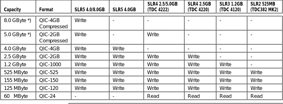
(11) ___________________________________________________________________. 1.. Introduction 1.1.. General. This manual covers the SCSI-2 Specifications for the SLR Series (TDC 4000) Series Drives. These series consist of six (6) different drive models: SLR5 4.0/8.0GB SLR5 4.0GB SLR4 2.5/5.0GB (TDC 4222) SLR4 2.5GB (TDC 4220) SLR3 1.2GB (TDC 4120) SLR2 525MB (TDC 3820 MK2) The specifications described in this publication are subject to change without notice.67, STANDARD The main difference between these Drives is the capacity. The following table shows the different capacities and read/write formats for each Drive: Capacity. Format. SLR5 4.0/8.0GB. SLR5 4.0GB. SLR4 2.5/5.0GB (TDC 4222). SLR4 2.5GB (TDC 4220). SLR3 1.2GB (TDC 4120). SLR2 525MB (TDC382 MK2). 8.0 GByte *). QIC-4GB Compressed. Write. -. -. -. -. -. 5.0 GByte *). QIC-2GB Compressed. Write. -. Write. -. -. -. 4.0 GByte. QIC-4GB. Write. Write. -. -. -. -. 2.5 GByte. QIC-2GB. Write. Write. Write. Write. -. -. 1.2 GByte. QIC-1000. Write. Write. Write. Write. Write. -. 525 MByte. QIC-525. Write. Write. Write. Write. Write. Write. 155 MByte. QIC-150. Write. Write. Write. Write. Write. Write. 125 MByte. QIC-120. Write. Write. Write. Write. Write. Write. 60 MByte. QIC-24. -. -. Read. Read. Read. Read. NOTE *): The capacity will depend on the compression ratio, typical values will be in the range from 2 to 3 times compression. The SLR5 4.0/8.0GB is functionally fully compatible with the SLR5 4.0GB, except that the SLR5 4.0/8.0GB has the capability to perform data compression. The SLR4 2.5/5.0GB (TDC 4222) is functionally fully compatible with the SLR4 2.5GB (TDC 4220), except that the SLR4 2.5/5.0GB (TDC 4222) has the capability to perform data compression. SLR2 525MB (TDC 3820 MK2) is fully compatible with SLR2 525MB. The MK2 version has some added functionality compared with the standard TDC 3800. If a certain functional specification is valid for a particular drive or a group of drives, two methods are used to separate the different specification throughout this manual: 1). The special functional specification is marked out with horizontal lines. 2). The validity for a certain functional specification is written directly in the text. All other text will be common for all SLR (TDC 4000) Series Drives.. 1-1. SCSI-2 Functional Specifications.
(12) Tandberg Data Introduction ___________________________________________________________________. 1.2.. Purpose of this Document. This publication specifies functional requirements for the SCSI-2 Host Interface for the SLR (TDC 4000) Series Drives. This document is meant as a complete specification of the functional behavior of the SCSI-2 Host Interface.. 1.3.. Overview. Chapter 2. General description of tape streamers in general and the SLR (TDC 4000) Series Drives in particular. The chapter also describes how to use Fixed and Variable Length blocks and QFA (Quick File Access).. Chapter 3. Gives a description of the SCSI logical characteristics as implemented by the SLR (TDC 4000) Series Drives.. Chapter 4. Specifies the SCSI Command Descriptors in general.. Chapter 5. Lists the Status Bytes implemented by the SLR (TDC 4000) Series Drives.. Chapter 6. Lists the Message Bytes implemented.. Chapter 7. Specifies the SLR (TDC 4000) Series Drives exception handling in general.. Chapters 8- 33. Hold detailed specifications for the individual SCSI-2 commands.. 1-2. SCSI-2 Functional Specifications.
(13) Tandberg Data Introduction ___________________________________________________________________. 1.4.. Glossary. BOM. Beginning Of Medium. The extreme position along the medium in the direction from the supply-reel which can be accessed by the use of a REWIND command.. BOP. Beginning Of Partition. The position at the beginning of the permissible recording region of a partition. If only one partition is defined, this position is equivalent to BOM (see above).. BOT. Beginning Of Tape. Physical marker on the tape marking the start of the useful area of the tape (located at BOM, see above).. CDB. Command Descriptor Block. The structure used to communicate commands from an Initiator to a Target.. Compression Block Group. A group of compressed data recorded as one variable block on the tape. The Compression Block Group either contains a number of Host-defined logical fixed blocks, or a complete or partial Host-defined variable logical block. The Compression Block Group also contains a Compression Header recorded at the beginning of the Compression Block Group.. Compression Header. A group of 10 bytes recorded as uncompressed data at the beginning of a Compression Block Group. The Header contains specific information related to the Compression Block Group recorded on the tape.. Disconnect. The action that occurs when a SCSI device releases control of the SCSI bus, allowing it to go to the BUS FREE phase.. EOD. End Of Data. End of data in a partition is defined in Section 1.5 [4].. EOM. End Of Medium. The extreme position along the medium in the direction from the take-up-reel which can be accessed by the device. This position may be accessed by the use of a LOAD/UNLOAD command with the EOT-bit set to one.. EOP. End Of Partition. The position at the end of the permissible recording area of a partition. If only one partition is defined, this position is equivalent to EOM (see above).. EOT. End Of Tape. Physical marker on the tape marking the end of the useful area of the tape (located at EOM, see above).. EW. Early Warning. Physical tape-mark near - but logically before - EOP (independent of physical direction).. Field. A group of one or more contiguous bits. Fields containing only one bit are usually referred to as the XX bit instead of the XX field.. Initiator. SCSI-bus Device issuing SCSI commands to a SCSI Target.. LED. Light Emitting Diode. An indicator on the front of the Drive.. LSB. Least Significant Bit. LUN. Logical Unit Number. 1-3. SCSI-2 Functional Specifications.
(14) Tandberg Data Introduction ___________________________________________________________________ MSB. Most Significant Bit. Overlength. The incorrect length condition that exists after executing a read group command, when the length of the actual block read exceeds the requested transfer length in the command descriptor block (CDB).. Page. Several commands use regular parameter structures that are referred to as pages. These pages are identified with a value known as a page code.. Parameter. A structure containing one or more fields.. Partition. The entire region of recording and reading paths in a volume or in a portion of a volume.. PSEW. Pseudo Early Warning. Simulated EW marker on the last track on the tape. PSEW is moved some distance in front of the actual EW.. Reconnect. The act of re-establishing the physical Initiator/Target connection. A Target reconnects to an Initiator by issuing RESELECTION and MESSAGE IN phases after winning arbitration.. Reserved. The term used for bits, fields and code values that are set aside for future standardization.. SCSI. Small Computer Systems Interface. Industry standard computer peripheral interface. Used to connect several devices via a common data and control bus.. SCSI address. The representation of the unique address (0-7) assigned to a SCSI device. This address would normally be assigned and set in the SCSI device during system initialization.. SCSI ID. The bit-significant representation of the SCSI address referring to one of the SCSI bus data lines.. Signal assertion. The act of driving a signal to the true state.. Signal de-assertion. The act of driving a signal to the false state.. Status. One byte of information sent from a Target to an Initiator upon completion of each command.. Third-party. When used in reference to RESERVE or RELEASE commands, thirdparty means a reservation made on behalf of another device.. Target. SCSI-bus Device receiving/executing SCSI commands.. TLA. Three Letter Acronym. Underlength. The incorrect length condition that exists after executing a read group command when the requested transfer length in the command descriptor block (CDB) exceeds the length of the actual block read.. Volume. A recording medium together with its physical carrier.. 1-4. SCSI-2 Functional Specifications.
(15) Tandberg Data Introduction ___________________________________________________________________. 1.5.. 1-5. Additional Reference Documentation [1]. Tandberg Data AS: "TDC 3620/3640/3660 Reference Manual", Publ. No. 5671, Part No. 41 13 59, "TDC 3800 Series Reference Manual", Publ. No. 5871, Part No. 42 22 38 and "SLR (TDC 4000) Series Reference Manual", Publ. No. 9048, Part No. 43 05 08.. [2]. American National Standards Institute, "SCSI-2, Enhanced Small Computer System Interface", ANSI Working Draft X3T9.2/86-109, Revision 10d, May 1. 1991.. [3]. Development Standard For 1/4-inch Cartridge Tape Drive SCSI-2 Interface, QIC-121, Revision F, August 21. 1990.. [4]. QIC, "Serial Recorded Magnetic Tape Cartridge For Information Interchange", QIC-525, Revision E, April 18. 1991.. [5]. QIC, "Serial Recorded Magnetic Tape Cartridge For Information Interchange", QIC-1000, Revision C, April 17. 1991.. [6]. QIC, "Serial Recorded Magnetic Tape Cartridge For Information Interchange", QIC-2GB, Revision B, March 10. 1994.. [7]. "Development Standard, Adaptive Lossless Data Compression (ALDC)", QIC-154, Revision A, March 10. 1994.. [8]. QIC, "Serial Recorded Magnetic Tape Cartridge For Information Interchange", QIC-4GB, Revision A, November 19. 1996.. SCSI-2 Functional Specifications.
(16) Tandberg Data Introduction ___________________________________________________________________. This Page Intentionally Left Blank. 1-6. SCSI-2 Functional Specifications.
(17) ___________________________________________________________________. 2.. About Tape Streamers 2.1.. Physical Elements Tape streamer devices optimize their use in storing or retrieving user data in a sequential manner. Since access is sequential, position changes typically take long time, when compared to direct-access devices like disks. The recording medium used with the Drive consists of a flexible substrate coated with a semi-permanent magnetic material. The recording medium is wound onto two reels.. Both the supply reel and the take-up reel are encapsulated into a cartridge. Several standards exist, covering the construction of cartridges for data interchange. A complete unit composed of the recording medium and its physical carrier (the cartridge) is called a volume. In tape streamers like the SLR (TDC 4000) Series Drives, volumes are removable. When a volume is loaded, the streamer device is capable of executing commands that cause the medium to be moved (so-called media access commands). When a volume is unloaded the media access commands cannot be executed (that is when these commands report CHECK CONDITION status and a NOT READY sense key). The write protected state determines when an Initiator may write information on a volume. This attribute is controlled by the user of the volume through the SAFEswitch on the cartridges. The recording medium has two physical attributes called beginning-of-tape (BOT) and end-of-tape (EOT). Beginning-of-tape is at the end of the medium that is attached to the take-up reel. End-of-tape is at the end of the medium that is attached to the supply reel.. 2.2. Serpentine Recording Method. Data Storage Characteristics. The position on the medium where a pattern of recorded signal may be written by one write component is called a track. The Drive is able to write only a single track at a time. On a new volume, recording of a track begins when moving the tape from Beginning-Of-Media toward End-OfMedia. When End-Of-Media is approached, the direction of recording is reversed and the Drive starts recording a track from End-Of-Media towards Beginning-Of-Media. This process repeats the number of times necessary to record all tracks. The total number of tracks depends on the tape format used. This method of recording is called serpentine. When reading in the forward direction the same course of tracks is followed as when writing.. 2-1. SCSI-2 Functional Specifications.
(18) Tandberg Data About Tape Streamers ___________________________________________________________________ From the Initiators point of view the medium may be looked upon as having one large continuous logical track starting from a position called beginning-of-media and ending at a position called End-Of-Media. Beginning-of-media is always on the same side of the volume as beginning-of-tape. End-of-media may be located at the beginning-of-tape or at the end-of-tape depending on whether the total number of tracks is odd or even. The logical track is split into several areas separated by markers. At least four parts may be identified:. BOT. LP. Beginning-Of-Media. Recording Area. EOT. EW. PSEW. Early-Warning Area. End-Of-Media. Beginning-Of-Media. This area holds no user data. It is used to record a special reference burst as defined in [4] and [5]. This area starts with the BOT (Beginning Of Tape) tape marker and ends at the LP (Load Point) tape marker.. Recording Area. This area holds most of the user data. This area starts with the LP (Load Point) tape marker and ends at the PSEW (Pseudo Early Warning) marker.. Early-Warning Area. When writing, the Initiator needs an indication that it is approaching the end of the Recording-Area. The position, called Pseudo Early Warning (PSEW) is reported to the Initiator at a position early enough for the Drive to write out any buffered data to the medium while still leaving enough room for additional recorded data or filemarks. It will usually be room for about 400 KBytes of data in the Early-Warning-Area (the actual amount of data is user configurable, see the PSEW Position field in Section 15.3.7.) This area ends at the EW (Early Warning) tape marker.. End-Of-Media. This is the short area between the EW (Early Warning) and the EOT (End-Of-Tape) tape markers. It is usually possible to complete the writing of a single last frame between EW and EOT. When this has been done or when EOT is found, all further write operations are discontinued even if the there are more data to be written in the data buffer.. 2.3.. Partitions Within a Volume. A volume may be split into several mini-volumes called partitions. Each partition has its own set of beginning and ending points. Each partition within a volume has defined its own Beginning-Of-Partition, RecordingArea, Early-Warning-Area and End-Of-Partition.. 2-2. SCSI-2 Functional Specifications.
(19) Tandberg Data About Tape Streamers ___________________________________________________________________ On a volume with N partitions the very first partition (partition zero), the Beginning-Of-Partition is identical to Beginning-Of-Medium. For the very last partition on a volume (partition N-1), the End-Of-Partition is identical to End-Of-Media. All volumes have a minimum of one partition called partition zero, the default data partition. When a volume is mounted (that is inserted into the Drive and then loaded), it is logically positioned to the beginning of the default data partition (partition zero). When a REWIND command is received in any partition, the Drive positions to the beginning of the current partition.. 2.4.. Quick File Access. Partitions can be used to support the implementation of QFA (Quick File Access). QFA is a feature which provides support for two partitions on the tape cartridge, a directory partition and a data partition. Quick File Access (QFA) is implemented in the Drive. The QFA mode can be enabled and disabled with the MODE SELECT command. When not in QFA mode the Drive will implement a single partition covering the whole tape. This single partition is called the Default Data Partition. Partition. Use. 0. Data. 1. Directory Information. Table: Partitions Within A Volume. 2-3. SCSI-2 Functional Specifications.
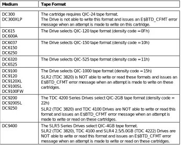
(20) Tandberg Data About Tape Streamers ___________________________________________________________________ In QIC compatible tape streamers like the SLR (TDC 4000) Series Drives, all partitions start on track boundaries at the physical BOT end of the tape. A single track is allocated to the directory partition. All remaining tracks are allocated to the data partition. The following table shows the directory track allocation for all supported tape formats:. Tape Format. SLR5 4.0GB, SLR5 4.0/8.0GB, TDC 4100, TDC 4200 and SLR4 2.5/5.0GB (TDC 4222) only. Recording Direction. Approximate Size. Directory Track Number. QIC-120 QIC-150 QIC-525 w/DC6320 QIC-525 w/DC6525 QIC-1000 w/DC9100. Forward Forward Forward Forward. 7.0 MByte 7.3 MByte 10.3 MByte 18.1 MByte. 14 17 25 25. Forward. 31.3 MByte. 29. QIC-1000 w/DC9120 QIC-1000 w/DC9120XL QIC-1000 w/DC9100SL QIC-1000 w/DC9100FW QIC-2GB w/DC9200. Forward Forward Forward Forward. 39.7 MByte 50.6 Mbyte 4.8 MByte 4.6 MByte. 29 29 29 29. Forward. 45.6 MByte. 41. Forward Forward. 5.8 Mbyte 58.2 MByte. 41 41. Forward. 88 MByte. 45. SLR5 4.0GB, SLR5 4.0/8.0GB, TDC 4200 and SLR4 QIC-2GB w/DC9200SL 2.5/5.0GB (TDC 4222) only QIC-2GB w/DC9250 SLR5 Series only QIC-4GB w/DC9400. Table: Directory Track Allocation. SLR5 4.0/8.0GB and SLR4 2.5/5.0GB (TDC 4222) only. NOTE: The data written in the directory partition is always uncompressed [6].. 2.4.1.. Setting the QFA-mode. The MODE SELECT command is used to enter the QFA mode. The Drive will be in non-QFA mode when the FDP bit in the Medium Partition Parameter Page (Page Code 11h) is set to zero. The Drive will be in QFA mode when the FDP bit is set to one. Setting or clearing this bit will only be legal when the tape is positioned at BOT or at the beginning of the Data Partition.. 2.4.2.. Changing Partitions Before Reading. The LOCATE command can be used to specify the active partition. The Change Partition (CP) must be set to one and the Partition field must be set to 0 (Data Partition) or 1 (Directory Partition). The Drive will then move to the specified partition before the actual block locate operation starts. The LOCATE command is only useful when executed on a pre-written tape (the block to locate must exist on the tape). The READ POSITION and MODE SENSE commands may be used to read the current partition number in use.. 2-4. SCSI-2 Functional Specifications.
(21) Tandberg Data About Tape Streamers ___________________________________________________________________ When the partition has been changed, the Drive will stay in the selected partition for all media access commands until one of the following actions are taken (by the Initiator): ● A new LOCATE with CP set to one is executed. ● A MODE SELECT command is executed that changes the state of the Active Partition field in the Device Configuration Parameters Page (page code 10h). This is only legal at BOT. ● A LOAD or ERASE command is executed. These commands always bring the tape to the beginning of the Data Partition. ● The cartridge is removed from the Drive. A newly inserted cartridge must be loaded before it can be accessed. The load operation positions the tape at the beginning of the Data Partition. This will be true whether the load operation happens as a result of an Auto Load or an explicit LOAD command.. 2.4.3.. Changing Partitions Before Writing. The MODE SELECT command can be used to specify the active partition. The Device Configuration Parameters Page (page code 10h) is used for this purpose. The Change Active Partition (CAP) bit must be set to one and the Active Partition field must be set to 0 (Data Partition) or 1 (Directory Partition). The Drive will then position the tape at the beginning of the specified partition. See Chapter 15. Mode Select. The MODE SELECT command can be used to change the active partition before a WRITE or WRITE FILEMARK operation is started. The READ POSITION and MODE SENSE commands may be used to read the current partition number in use. When the partition has been changed, the Drive will stay in the selected partition for all media access commands until one of the following actions are taken (by the Initiator): ● A new MODE SELECT command is executed that changes the state of the Active Partition field. This is only legal at BOT. ● A LOCATE with CP set to one is executed. ● A LOAD or ERASE command is executed. These commands always bring the tape to the beginning of the Data Partition. ● The cartridge is removed from the Drive. A newly inserted cartridge must be loaded before it can be accessed. The load operation positions the tape at the beginning of the Data Partition. This will be true whether the load operation happens as a result of an Auto Load or an explicit LOAD command.. 2-5. SCSI-2 Functional Specifications.
(22) Tandberg Data About Tape Streamers ___________________________________________________________________. 2.4.4.. General QFA-rules on Write. The following rules applies to QFA-operation on WRITE: ● Write from BOT on DATA-partition: - always OK ● Write from BOT on DIRECTORY-partition: - only allowed if data is already read/written on DATA-partition, and no reset, power-up or cartridge change has been detected since the Read/Write operation in the DATA-partition was executed. The data on DATA-partition may initially be read/written in single or dual partition mode and -. data has not been written from BOT on DIRECTORY partition. ● Append on DATA-partition: - is always OK, either if the initial WRITE operation from BOT was done in single partition or dual mode ● Append on DIRECTORY-partition: - is always OK if data has been detected on the DIRECTORYpartition NOTE: General rule: Always assure that more data is written on the DATApartition than on the DIRECTORY-partition. When writing the first track (Track 0) on DATA-partition, all other tracks are ERASED including the DIRECTORY-partition. This is not the case when writing from BOT on the DIRECTORY-partition, i.e. no ERASE of old data. Thus, if writing more on the DIRECTORY-partition than on the DATA-partition, an overwrite of old data on the DIRECTORY-partition may be the case if the tape is not fully erased prior to this operation. This may corrupt the data on the DIRECTORYpartition. Furthermore, if an APPEND on the DATA-partition is given after this scenario, the last data recorded on the DIRECTORY-partition will be ERASED.. 2-6. SCSI-2 Functional Specifications.
(23) Tandberg Data About Tape Streamers ___________________________________________________________________. 2.5.. Logical Elements Within a Partition. The Recording-Area on a volume may contain two types of Initiator accessible elements; data blocks and tape marks. These elements are controlled and transferred between the Initiator and the medium using READ, WRITE and WRITE FILEMARKS commands. A unit of data supplied or requested by the Initiator is called a logical block. Logical blocks are stored according to the specifications of the tape format used [4] and may be recorded as one or more physical blocks on the medium. When the physical block and the logical block are not recorded in a one-to-one relationship, it is the responsibility of the device to perform all blocking, de-blocking or padding of the logical block(s) sent to/from the Initiator. Filemarks are one kind of tape marks. Filemarks are special recorded elements containing no user data. Initiators traditionally use filemarks to separate user data from labels and logical groupings of data from each other. Setmarks are another kind of tape marks. Setmarks are special recorded elements containing no user data, providing a segmentation scheme hierarchically superior to filemarks. Each data block on the tape has a CRC-code attached. The purpose of this code is to make certain the correctness of the data in the block. The CRC-code is 4 bytes long for QIC-4GB, QIC-2GB, QIC-1000 and QIC-525 and 2 bytes long for QIC-150, QIC-120 and QIC-24. The CRC-check operation is transparent to the Initiator. Interblock gaps, the gaps between blocks, filemarks and setmarks, are introduced on the medium at the time a block or tape mark is written without explicit action by the Initiator. Minimum and maximum lengths for interblock gaps are defined in [4]. In addition to blocks, tape marks and inter-block gaps erase gaps can be recorded. An erase gap is automatically recorded when a write operation is properly terminated as an end-of-data marker. In addition a single erase gap may be recorded on the medium through the use of the ERASE command. This erase gap will cover the whole medium and all pre-recorded information will be written over and lost. The Drive is capable of supporting both fixed and variable length logical blocks. The concept of fixed or variable mode for writing and reading blocks only indicates the method by which the Initiator specifies the size of the logical block for transfer and not the method of recording physical blocks on the medium.. 2-7. SCSI-2 Functional Specifications.
(24) Tandberg Data About Tape Streamers ___________________________________________________________________. 2.6.. Using Fixed and Variable Length Blocks. 2.6.1.. Variable and Fixed Length Blocks. When reading or writing the Drive groups data transferred to/from the Initiator into blocks. The length of a block may vary. When executing read and write commands two parameters must be specified; the block length and also the number of blocks to read or write. As the SCSI read and write commands only have room for a single parameter, only the block length or the number of block can be specified directly. For this reason there are two different versions of each command capable of transferring tape data to or from the Initiator. The fixed length type commands can specify the number of blocks to be processed. For these commands all blocks will be of equal size. The actual size is given by the current value in the Block Size field in the Block Descriptor List of the MODE SELECT command. The variable length type commands can specify the length of the individual blocks, but the number of blocks written is always only one (for each command). When the Block Size field has a value different from zero, the Drive is said to be in fixed block mode. In this mode both the fixed length type commands and the variable length type commands are allowed. When the Block Size field is zero, the Drive is said to be in variable block mode. In this mode only the variable length type commands are allowed (as writing fixed length blocks of zero (0) bytes has no meaning). NOTE: The illegal length handling in the READ command differs slightly depending on the current mode.. 2.6.2.. Writing. When writing, the Drive groups the data transferred from the Initiator into blocks. When using the QIC-525/1000/2GB and QIC-4GB tape format a block can be from 1 to 16777215 bytes long. When using the QIC-120 or QIC-150 tape formats it may be from 1 to 32786 bytes long. Data blocks may be written with two different versions of the WRITE command; one with the fixed (FIX) bit set and one with the fixed (FIX) bit cleared. When the FIX bit is cleared, a WRITE command will write a single block. The block length may be specified on a block-by-block basis. This is useful when writing blocks of varying length. When the FIX bit is set to one, a WRITE command may write multiple blocks. The WRITE command must specify the number of blocks to write. All written blocks will be of the same length. The length used is the length reported by the MODE SENSE command (the Block Size field of the Block Descriptor List). Note that when the Block Size field has been set to zero, the Drive is said to be in Variable Block mode and commands with the FIX bit set to one is not allowed.. 2-8. SCSI-2 Functional Specifications.
(25) Tandberg Data About Tape Streamers ___________________________________________________________________. 2.6.3.. Reading. When reading data off a tape, the Drive is able to determine the length of each block read. When reading, the expected block length must be specified. This can be done in two different ways with the two different versions of the READ command; one with the fixed (FIX) bit set and one with the fixed (FIX) bit clear. When the FIX bit is clear, a READ command will read a single block. The expected block length may be specified on a block-by-block basis. When the FIX bit is set to one, a READ command may read multiple blocks. The READ command must specify the number of blocks to read. The expected block length of all blocks is the same. The expected length is specified with the MODE SELECT command(the Block Size field of the Block Descriptor List). Note that when the Block Size field has been set to zero, the Drive is said to be in Variable Block mode and commands with the FIX bit set to one is not allowed.. 2.6.4.. Illegal Length Conditions when Reading. When the specified block length does not match the actual block length, the READ command will complain (if not the Suppress Illegal Length Indicator (SILI) bit was set in the READ Command Descriptor Block). 2.6.4.1. Reading with the Fixed-Bit Clear If the actual block length is smaller then the expected block length (the length specified in the Command Descriptor Block of the READ command), the READ command will transfer the actual number of bytes found in the block. The READ command is then terminated with a CHECK CONDITION Status. The Illegal Length Indicator will be set in the Sense Data List. The Information Bytes will be set to the difference between the expected number of bytes and the actual number of bytes. This will be a positive number in this case. The logical tape position will be at the beginning of the next block on the tape. If the actual block length is larger than the expected block length, the READ command will transfer the expected number of bytes only. The READ command is then terminated with a CHECK CONDITION Status. The Illegal Length Indicator will be set in the Sense Data List. The Information bytes will be set up with the difference between the expected number of bytes and the actual number of bytes. This will be a negative number in this case. The information bytes is presented as a 32 bit 2's complement number. The logical tape position will be at the beginning of the next block on the tape. This means that the additional bytes in the block with the unexpected length is lost.. 2-9. SCSI-2 Functional Specifications.
(26) Tandberg Data About Tape Streamers ___________________________________________________________________ 2.6.4.2. Reading with the Fixed-Bit Set If the actual block length is smaller then the expected block length, the READ command will transfer the actual number of bytes found in the block. The READ command is then terminated with a CHECK CONDITION Status. The Illegal Length Indicator will be set in the Sense Data List. The Information Bytes will be set to the difference between the specified number of blocks and the actual number of blocks transferred. The block with the unexpected length is counted among the transferred blocks even if its length was wrong. Note that this means that the Information Bytes may read zero even if the READ command was terminated with CHECK CONDITION and Illegal Length Indication. The logical tape position will be at the beginning of the block following the block with the unexpected length. If the actual block length is larger than the expected block length, the READ command will transfer the expected number of bytes only. The READ command is then terminated with a CHECK CONDITION Status. The Illegal Length Indicator will be set in the Sense Data List. The Information bytes will be set up with the difference between the specified number of blocks and the actual number of blocks transferred. The block with the unexpected length is counted among the transferred blocks even if its length was wrong. Note that this means that the Information Bytes may read zero even if the READ command was terminated with CHECK CONDITION and Illegal Length Indication. The logical tape position will be at the beginning of the block following the block with the unexpected length. This means that the additional bytes in the block with the unexpected length is lost.. 2-10. SCSI-2 Functional Specifications.
(27) Tandberg Data About Tape Streamers ___________________________________________________________________. 2.7.. Data Buffering. 2.7.1.. Introduction. The Drive has a temporary storage area capable of holding one or more blocks - a data buffer. The data buffer may hold any combination of data blocks, filemarks and setmarks in the process of being written to the medium, or it may contain read-ahead datablocks and filemarks transferred from the medium. The data buffer operates as a FIFO queue, compensating for the different transfer rates on the SCSI-bus and the tape system. The Drive is usually only connected to the SCSI-bus for short amounts of time when bursts of data are transferred at a much higher speed than the normal tape transfer rate. The data buffer can be in one out of two modes; read mode or write mode. The data buffer is in write mode when executing COPY (backup), WRITE or WRITE FILEMARKS commands. The data buffer is in read mode when executing COPY (restore), LOCATE, READ, SPACE or VERIFY commands. The physical buffer is split into three areas: The Scratch Pad Area. The size of this area is 16 KBytes (16384) bytes. The Scratch Pad Area is used as a scratch pad for several of the SCSI commands. A typical example is the COPY command which uses about 3 KByte of this area to hold its Segment Descriptor List.. The ECC Block Buffer Area. The size of this area is 30 KBytes (30720) bytes. The ECC Block Buffer Area is used to hold the ECC blocks for every complete frame that is currently in the Data Buffer Area.. The Data Buffer Area. The size of this area is 210 KBytes (215040) bytes. This is the area used to buffer blocks and filemarks. Only the Data Buffer Area is used to buffer user data and filemarks.. 2.7.2.. Blocks. On both the SCSI-bus side and the tape side of the data buffer data is grouped into blocks. Blocks on the SCSI-bus side is called logical blocks. Blocks on the tape side is called physical blocks. When using the QIC-525/1000/2GB/96-34 tape format 14 physical blocks are again grouped into a frame. As long as data is moving through the Data Buffer Area it is grouped into physical blocks. The blocking and de-blocking into logical blocks is done on the SCSI-bus side of the buffer. When operating in QIC-525/1000/2GB/96-34 mode the Data Buffer Area can hold a maximum of 210 blocks (1024 bytes each). When operating in QIC-150, QIC-120 or QIC-24 mode the maximum number of blocks in the Data Buffer Area is also 210 (512 bytes each).. 2-11. SCSI-2 Functional Specifications.
(28) Tandberg Data About Tape Streamers ___________________________________________________________________ Note, however, that since one block is always reserved in both read and write mode and two more blocks are reserved for the tape re-write algorithm in write, the effective size of the buffer is 209 physical blocks in read mode and 207 physical blocks in write mode.. 2.7.3.. Blocking/De-blocking. The size of a logical data block may not be the same as the size of a physical data block. On the tape side of the data buffer the block size is given by the size of the physical tape blocks. This size depends on the tape format used. The QIC-24, QIC-120 and QIC-150 tape formats uses 512 byte physical blocks. The QIC-525/1000/2GB/96-34 uses 1024 byte physical blocks. On the bus side of the data buffer the size of a block may vary. When using READ and WRITE commands with the FIXED bit set to zero the actual size is specified in the Command Descriptor Block. When the FIXED bit is set to one the block size is controlled by the Block Size field in the MODE SELECT Block Descriptor List. Fixed block sizes of 512 and 1024 bytes are supported in QIC-525/1000/2GB/96-34 mode while only 512 bytes are supported in QIC-120/150 mode. When operating in write mode, data transferred into the buffer from the SCSI-bus is grouped into physical blocks on the bus side of the data buffer. When operating in read mode data is de-blocked at the bus side of the data buffer before transferred to the SCSI-bus. This means that the data buffer always buffers one or more physical tape blocks. Note also that every tapemark occupies one physical tape block in the data buffer. The same is true for control blocks and filler blocks. One logical block usually occupies at least one complete physical block. When the tape format is QIC-525/1000/2GB/96-34 this means that logical blocks with a size less then or equal to 1024 bytes occupies one physical block. Logical blocks with a size in the range 1025 bytes to 2048 bytes occupies two physical blocks etc. There is one exception to this rule. When writing 512 byte blocks with the FIXED bit set to one a special option is used in the QIC-525/1000/2GB/96-34 standard allowing two logical blocks to share one physical block. When the tape format is QIC-120 or QIC-150 every logical block written with the FIXED bit set to zero occupies at least two physical blocks in the buffer. Logical blocks with a size less than or equal to 512 bytes occupies two physical blocks. Logical blocks with a size in the range 513 bytes to 1024 bytes occupies three physical blocks etc. Logical blocks written with the FIXED bit set to one occupies one single physical block.. 2-12. SCSI-2 Functional Specifications.
(29) Tandberg Data About Tape Streamers ___________________________________________________________________. 2.7.4.. Buffered Mode. The Drive is capable of operating in both a buffered mode and an unbuffered mode. Buffered mode is not applicable during read commands. When operating in buffered mode the Drive returns GOOD status for write operations when all data has been successfully transferred from the Initiator into the data buffer. When operating in unbuffered mode, GOOD status is not returned until all requested data or filemarks are successfully recorded on the medium. When issuing a buffered WRITE FILEMARKS command with the immediate bit set to one, GOOD status is returned as soon as the filemark(s) has been moved into the data buffer. A WRITE FILEMARKS command with the immediate bit set to zero causes any buffered data blocks or filemarks to be written to the medium. Upon successful completion of this process, which is called a synchronize operation, no data blocks or filemarks remain in the data buffer. Should an unrecoverable write error occur while in buffered mode, the Drive generates an error condition to the current active command. If no command is active, the error is reported on the next applicable operation as a deferred error. Note that when operating in buffered mode with the QIC-525/1000/2GB/96-34 tape format the Drive will pack physical blocks from one WRITE or WRITE FILEMARKS command together with physical blocks from the previous WRITE or WRITE FILEMARKS command into the same frame. This is not true when operating in nonbuffered mode. If a WRITE or WRITE FILEMARKS command does not transfer enough data (or filemarks) to fill a complete frame (14 KBytes or 14 filemarks) the rest of the frame is filled up with filler blocks. This may of course waste a lot of space on a tape. When reading a tape containing frames with filler blocks the Drive is able to remove the filler blocks without generating any discontinuities in the data stream on the SCSI-bus. Note, however, that even if filler blocks are inserted and removed automatically by the Drive they will occupy buffer space both in read mode and write mode.. 2.7.5.. Read-Ahead. When operating in read mode the Drive always try to fill up the buffer with read-ahead data. This means that when a read type command terminates the Drive continues to read data off the tape. The read-ahead only stops when the data buffer is full, if a non-read command is issued or if there is no more data to read. The read-ahead also stops when an uncorrectable block has been detected. Read-ahead minimizes tape start and stops because when a read type commands (including SPACE and VERIFY) follows another read type command the wanted data might already be ready in the data buffer. When an error has been detected by the tape system the Drive does not report the error until all data up to point where the error occurred has been read out of the data buffer. This means that if an unrecovered read error has occurred this error is not reported until the data block in error is requested by an Initiator.. 2-13. SCSI-2 Functional Specifications.
(30) Tandberg Data About Tape Streamers ___________________________________________________________________. 2.7.6.. Underrun/Overrun. When the Drive is in write mode data are moved from the data buffer on to the tape. The tape write operation can only continue as long as there are any data left to write in the data buffer. If the buffer for any reason becomes empty the write operation must be stopped. This can happen if the Initiator is too slow transferring data or if the Drive is configured in non-buffered mode. When the tape is stopped in this way an underrun condition has occurred. Note, however, that the tape is not stopped immediately. The Drive is able to delay the stopping for some limited amount of time. This may be controlled by the Initiator by manipulating the Forced Streaming Count in the Miscellaneous Parameters Page (see the MODE SELECT command). When the data buffer later becomes non-empty the tape write operation can continue (see also Section 2.7.7) When the Drive is in read mode data are moved from the tape and into the data buffer. If the data buffer becomes full the tape read operation must be stopped immediately. This can happen if the Initiator is too slow transferring data or if the Initiator has stopped issuing READ, SPACE or VERIFY commands(remember the tape read-ahead). When the tape is stopped in this way an overrun condition has occurred. When the data buffer later is emptied the tape read operation may continue(see also Section 2.7.7).. 2.7.7.. Buffer Thresholds. The data buffer acts like a large FIFO. When operating in write mode data blocks, control blocks, filler blocks and filemarks are inserted in one end of this FIFO and the same data and filemarks are later removed (and written to the tape) at the other end. The insertion of control blocks and filler blocks are transparent to the user (the SCSI Initiator). TAPE SIDE. SCSI-BUS SIDE Blocks going IN. B. B. B. Blocks going OUT. When moving data into the data buffer data blocks are entered a certain number at the time. If there is no space for the desired number then no data blocks are entered at all. This number is called a buffer threshold. There must usually be at least room for buffer threshold data blocks before new data are transferred in from the SCSI-bus. This will minimize the number of disconnects/reconnects. When transferring data blocks out of the FIFO and onto the tape a similar mechanism exists. When the FIFO for some reason is empty (an underrun condition), the tape write operation will not be started again until the number of blocks (data, control, filler, ECC or filemarks) ready in the FIFO is equal to or larger than another buffer threshold. This will have a tendency to minimize the number of tape start and stops (underrun conditions).. 2-14. SCSI-2 Functional Specifications.
(31) Tandberg Data About Tape Streamers ___________________________________________________________________ When the Drive is operating in read mode data blocks, control blocks, filler blocks and filemarks are moved from the tape and into one end of the data buffer. The data blocks and filemarks are later moved out (and transferred on the SCSI-bus) at the other end. Control blocks and filler blocks are just skipped. TAPE SIDE. SCSI-BUS SIDE B. Blocks going OUT. B. B. Blocks going IN. In read mode there are also two buffer thresholds; one controlling the tape read operation and one controlling the SCSI-bus transfer. These thresholds work in much the same way as when the Drive is in write mode. Note, however, that the bus threshold is overridden if the reason for not reaching the threshold value is that a filemark or some kind of error message is waiting in the data buffer. In this case the data in front of the filemark or error message is transferred even if the total amount of data is less than the configured buffer threshold. As can be seen there are 4 different buffer thresholds: Write Mode SCSIbus Threshold. This is the threshold used when moving data (not filemarks) from the SCSI-bus into the data buffer in write mode. This threshold is controlled by the Write Buffer Empty Ratio (see the MODE SELECT command). By manipulating the Write Buffer Empty Ratio the threshold can set to a minimum of 512 data bytes and a maximum of 65024 bytes. When operating in QIC-120 or QIC-150 mode (with a physical tape block size of 512 bytes) this corresponds to a minimum of 1 physical data block and a maximum of 127 physical datablocks. In QIC-525/1000/2GB/96-34 mode (with a physical tape block size of 1024 bytes) the corresponding numbers are 1 physical data block and 64 physical data blocks (data is taken out 1024 bytes at the time on the tape side of the data buffer).. Write Mode Tape Threshold. This is the threshold used when moving physical data, control, filemarks, filler or ECC blocks from the data buffer and onto the tape in write mode. This threshold is controlled by the Write Buffer Full Ratio (see the MODE SELECT command). By manipulating the Write Buffer Full Ratio the threshold can be set to a minimum of 1 physical block and a maximum of 68 physical blocks (regardless of physical block size).. Read Mode SCSIbus Threshold. This is the threshold used when moving data (not filemarks) from the data buffer to the SCSI-bus in read mode. This threshold is controlled by the Read Buffer Full Ratio (see the MODE SELECT command). By manipulating the Read Buffer Full Ratio the threshold can set to a minimum of 512 bytes and a maximum of 65024 bytes. When operating in QIC-120 or QIC-150 mode (with a physical tape block size of 512 bytes) this corresponds to a minimum of 1 physical data block and a maximum of 127 physical data blocks. In QIC-525/1000/2GB/96-34 mode(with a physical tape block size of 1024 bytes) the corresponding numbers are 1 physical data block and 64 physical data blocks (to get out 512 bytes of a 1024 byte block the whole block must have been moved into the other end of the data buffer).. 2-15. SCSI-2 Functional Specifications.
(32) Tandberg Data About Tape Streamers ___________________________________________________________________ Read Mode Tape Threshold. This is the threshold used when moving data from the tape into the data buffer in read mode. This threshold is controlled by the Read Buffer Empty Ratio (see the MODE SELECT command). By manipulating the Read Buffer empty Ratio the threshold can be set to a minimum of 1 physical block and a maximum of 68 physical blocks (regardless of physical tape block size). Note that when the Drive is writing in QIC-525/1000/2GB/96-34 mode blocks are released for writing at the tape side of the data buffer in complete frames. A frame is collection of 16 QIC-525/1000/2GB/96-34 blocks (1024 bytes each). A maximum of 14 blocks can hold data or filemarks. The two last blocks in a frame is always ECC blocks generated automatically by the buffer system. The ECC blocks do, however, not take up any space in the data buffer. This means that even if there is more blocks in the buffer than specified by the tape threshold these blocks will not be visible for the tape side of the data buffer until there is enough data to build a complete frame. Frames are normally not built until there is at least 14 full QIC-525/1000/2GB/96-34 data or filemark blocks ready in the data buffer. Note, however, that when the Drive operates in non-buffered mode each WRITE command will fill up the last frame with filler blocks (and thereby forcing generation of a complete frame). When the Drive is reading in QIC-525/1000/2GB/96-34 mode data is also released for use by the SCSI-bus handler in complete frames. This means that even if there is enough data in the data buffer to satisfy the bus threshold this data will not be visible on the bus side of the data buffer until there is enough blocks (data, control, filemark, filler or ECC blocks) to build a complete frame.. 2.7.8.. Deadlock Prevention - Read. When using large buffer thresholds on both the bus side and the tape side of the data buffer there might be a danger of getting into a deadlock situation. This could happen if the sum of the bus threshold (measured in physical tape blocks) and the tape threshold is larger than the maximum number of data blocks available in the data buffer. When operating in QIC-120 and QIC-150 mode, the bus threshold can be set to a maximum of 127 physical data blocks. The tape threshold can be set to a maximum of 68 physical blocks (of any type). This gives a sum of 195 blocks. Since the data buffer can hold at least 207 blocks this does not seem to make it possible to get into any problems with deadlocks. When operating in QIC-525/1000/2GB/96-34 mode the bus threshold can be set to a maximum of 64 physical data blocks. The tape threshold can be set to a maximum of 68 physical blocks (of any type). When taking into account that only complete frames can pass through the data buffer this gives a sum of 81 blocks (assuming the worst case of 13 blocks in the last incomplete frame) and the chance of getting into a deadlock seems even more remote. Problems may, however, arise in read mode because the bus threshold specifies a number of data blocks. In certain instances the data buffer may be filled up with large numbers of non-datablocks. This means that the number of blocks holding data maybe much less than 208! This can happen in certain situations in read mode when reading fixed length logical blocks.. 2-16. SCSI-2 Functional Specifications.
(33) Tandberg Data About Tape Streamers ___________________________________________________________________ One extreme example:. A tape written with WRITE commands specifying transfer of single fixed length logical blocks in unbuffered mode when the tape format is QIC-525/1000/2GB/96-34. This tape will only have 512 bytes of data in each frame. This means that of the 14 available physical blocks in a frame only the first physical block will have data (and only 512 bytes). When reading this tape the data buffer can hold a maximum of 14 complete frames (209 div 14). This means that the data buffer is only able to hold 7168 (512*14) bytes of data. If the bus threshold is set to its maximum value of 65024 bytes it is clear that the possibility of a deadlock is very real even if the tape threshold is set to its minimum value!. Another example:. When using the QIC-120 or QIC-150 tape format the tape is written with WRITE commands specifying 512 bytes of variable length data (FIXED bit set to zero). This tape will have a control block for every data block. When reading this tape the data buffer can hold a maximum of 104 physical data blocks (209 div 2). This is again less than the maximum bus threshold of 65024 bytes (127 physical data blocks). To prevent deadlock the Drive has a special mechanism that will start the data transfer to the SCSI-bus even if the number of available data blocks in the data buffer is less than the configured bus threshold. This means that in certain instances the amount of data transferred in a burst on the SCSI-bus might be less than expected (that is less than the amount configured by the Read Buffer Full Ratio).. 2.7.9.. Disconnect/Re-connect. When the Drive is operating in write mode no data transfer will be initiated until the data buffer can accept the amount of data set up by the current write bus threshold. Instead the Drive disconnects from the SCSI-bus freeing the bus for use by other devices. As soon as the data buffer can accept the data, the Drive reconnects and transfer a burst of data. The size of a burst is usually equal to the bus threshold. If still more data are requested for transfer the Drive then disconnects again. A reconnect later will transfer another burst and the whole process repeats until all requested data has been transferred. When the Drive is operating in read mode no data transfer will be initiated until the data buffer has ready the amount of data set up by the current read bus threshold. Instead the Drive disconnects waiting for enough data to become ready. When this happens (or a filemark or error message has been detected), the Drive reconnects and transfers a burst of data. The size of the burst is again controlled by the bus threshold. If still more data are requested for transfer the Drive then disconnects again. A reconnect later will transfer another burst and the whole process repeats until all requested data has been transferred. The Drive will NOT disconnect if not allowed by the initiator of the Read or Write command. See Section 6.2. As long as the requested transfer length is larger than the bus threshold all burst except the very last one will be of equal size (as long as nothing unexpected like an error occurs). The last burst will be equal or shorter in length than the other bursts (depending on the total requested transfer length). No burst will ever be larger than the configured bus threshold. This means that the bus threshold (as set by the Write Buffer Empty Ratio and Read Buffer Full Ratio) also control the maximum burst size. Note that in some special cases there are some exceptions to these rules. See Section 2.7.7 for further details.. 2-17. SCSI-2 Functional Specifications.
(34) Tandberg Data About Tape Streamers ___________________________________________________________________. 2.7.10. Data Re-transfer As a part of its bus parity error handling the Drive is able to re-transfer the last transferred burst any number of times. Re-transfer in the Data Out phase is automatically disabled if disconnects are not allowed. (Identify message = 80h). When receiving data in write mode the Drive may optionally check for parity errors in the data received. When the complete data burst has been transferred the Drive changes from the Data Out phase to the Message In phase. A single RESTORE POINTERS message is then transferred to the Initiator. The Initiator should in response to this message reset its data pointer to where it was when the Drive instructed it to save its pointer the last time (with the SAVE DATA POINTER message sent each time the Drive disconnects) or if no such message has been received set the pointer back to where it was when the write type command was issued. The Drive then re-enters the Data Out phase and transfers the last burst of data once more. The whole process can be repeated any number of times as long as the Drive detects parity errors in the received data. When transferring data to the Initiator in read mode the Initiator may check for parity errors in the received data. When a parity error has been detected the Initiator may assert the ATN. After having transferred the complete data burst the Drive will honor the ATN condition by going from the Data In phase to the Message Out phase. A message is then transferred from the Initiator. If this message is an INITIATOR DETECTED ERROR message the Drive will assume that the Initiator wants to have the last burst of data transferred once more. The Drive then goes to the Message In phase and transfers a single RESTORE POINTERS message. The Initiator should then reset its data pointer to where it was when the Drive instructed it to save its pointer the last time (with the SAVE DATA POINTER message sent each time the Drive disconnects) or if no such message has been received set the pointer back to where it was when the read type command was issued. The Drive then re-enters the Data In phase and transfers the last burst of data once more. The whole process can be repeated any number of times as long as the Initiator asserts ATN during the data transfer.. SLR5 4.0/8.0GB and SLR4 2.5/5.0GB (TDC 4222) only. When the data is compressed, re-transfer of data is not possible. The Drive will go from the Data-Out or Data-In phase to the CHECK CONDITION status phase if a parity error is detected. The Error Code will be set to E$STP_MEMP. The Initiator will then reset its data pointers to where they were when the last READ/WRITE type command was issued. If a parity error is detected during a WRITE operation, the current Compression Block Group will not be written to the tape. If this situation occurs in the middle of a logical block, the logical block will be terminated before all data has been written to the tape. This situation is only valid for logical blocks larger than 32 KBytes. For smaller logical blocks, the logical block(s) will be terminated as OK, but any logical block(s) in the last transfer is (are) not written to the tape. If a parity error is detected during a READ operation, the current Compression Block Group must be re-read. The Initiator should perform the last READ operation once more.. 2-18. SCSI-2 Functional Specifications.
(35) Tandberg Data About Tape Streamers ___________________________________________________________________. 2.7.11. Buffer Parity Errors The Drive may optionally check for parity errors in the data buffer. A buffer parity error is regarded as a fatal error and no recovery is attempted by the Drive. This means that even if the Drive signals a buffer parity error bad data may have been transferred to the Initiator or to the tape. The Drive has three checks for buffer parity error: ● Data moved from the data buffer to the SCSI-bus is checked while leaving the data buffer. A buffer parity error check is made at the end of a complete data burst. At this time the current command is terminated with CHECK CONDITION status. ● Data moved from the data buffer to the tape formatter hardware is checked while leaving the data buffer. A buffer parity error check is made at the end of physical block transfer. The current command is terminated as soon as possible. If a data transfer is taking place from the SCSI-bus to the data buffer, the current command is not terminated until this burst of data has been completed. If no command is active when the data buffer parity error is detected then the next command issued will terminate immediately with CHECK CONDITION status. ● Internal data transfers (like ECC generation and ECC correction) are checked for buffer parity errors at the end of an internal buffer operation. The current command is terminated as soon as possible. If a data transfer is taking place moving data to or from the SCSIbus, the command is not terminated until this burst of data has been completed. If no command is active when the data buffer parity error is detected then the next command issued will terminate immediately with CHECK CONDITION status.. 2.8.. Recorded Objects. The QIC recording formats specify that recorded elements (blocks, filemarks and setmarks) have identifiers included in the recorded information to help determining the write sequence and also to help detecting positioning errors. These identifiers are unique within the whole volume. The identifiers are associated with physical blocks only. This means that a possible logical block number maintained by the host system will not be the same as the physical identifier of the same logical block because logical blocks may span over multiple physical blocks. The physical identifiers are normally not visible to the host system. There are, however, some exceptions. In the SLR (TDC 4000) Series Drives, the READ POSITION and LOCATE commands transfer physical block identifiers to/from the host system. The host system is, however, not expected to process this data in any way. The identifiers read from the Drive is just stored and then sent unmodified back to the Drive at some future time.. 2-19. SCSI-2 Functional Specifications.
Figure
Outline
Buffer Thresholds
Command Sequencing
Extended Message
Abort Message Handling
Bus Parity Error Handling
The Information Bytes are updated with the difference between the requested and the actually processed blocks/bytes for the current
Load/Unload
Buffer Overrun/Underrun Counters Page
Block Descriptor List
Miscellaneous Parameters Page
Related documents
20 East Elmbridge Primary Care Mental Health Team Carers Support Workers 020 8873 4300 Mid Surrey Continuing Needs Service (Mental Health) Carers Support Worker
Long-term challenges include the doctor shortage in both Windsor-Essex and Ontario; the continued need to recruit physicians to the Windsor-Essex region; and the need to develop
Activities: outsourced management services of medical devices and ICT systems and supplies, integrated solutions of e-Health & e-Government (medical IT and IT
“Assessment” tab. Click on the “Start the Assessment” link to open the Assessment window. The Assessment entry screen will appear. You are able to practice the assessments
In other words, Virtual Volumes makes SAN and NAS storage systems capable of being managed at a virtual machine level and enables the leveraging of array- based data services
sonography versus saline infusion sonohysterography, which has better diagnosing accuracy in detecting cause of abnormal uterine bleeding in perimenopausal women. Int J
Interestingly, the combination with anti-PDL1 reversed the accumulation of PI3K activated myeloid cells (previously associated with both antiangiogenic and immunotherapy resistance)
However, the more different classes of vowels (the more complications to the calculation of stress) the less likely it seems that an indirect sound change (one that does
