USPEX
A
Copyright
Copyright © 1996 Auspex Systems, Inc. All rights reserved. Printed in the United States of America. Part Number 85-0337 Revision A, March 1997.
No part of this publication may be reproduced, in any form or by any means, without the prior written consent of Auspex Systems, Inc.
Auspex Systems, Inc., reserves the right to revise this publication and to make changes in content from time to time without obligation on the part of Auspex Systems to provide prior notification of such revision or change.
RESTRICTED RIGHTS LEGEND: Use, duplication, or disclosure by the Government is subject to restrictions as set forth in subparagraph (c)(1)(ii) of the Rights in Technical Data and Computer Software Clause at DFARS 252.227-7013 (October 1988) and FAR
52.227-19(c) (June 1987) and in similar clauses in the FAR and NASA FAR supplement.
Trademarks
Auspex, Auspex logo design, Functional Multiprocessor, Functional Multi-processor, Functional Multi-processing, Functional Multiprocessing Kernel, FMK, FMP, and NS 5000 are registered trademarks of Auspex Systems, Inc. NS 7000, NS 6000, NS 6002, NS 5500, NS 5502, NS 3000, NetServer, DataGuard, ServerGuard, and Functional Multiprocessing are trademarks of Auspex Systems, Inc.
AXXiON is a trademark of OpenVision Technologies, Inc. SPARC is a registered trademark of SPARC International. Sun, SunOS, Network File System, NFS, and Sun Microsystems are trademarks or registered trademarks of Sun Microsystems, Inc. UNIX is a registered trademark of X/Open Company Limited. VMEbus is a trademark of VMEbus
Manufacturers Group. VT510 and DEC are trademarks of Digital Equipment Corp. ForeRunner is a trademark of FORE Systems, Inc.
FCC Statement
WARNING: This equipment has been tested and found compliant with the limits for a Class A digital device, pursuant to Part 15 of the FCC rules. These limits are designed to provide reasonable protection against harmful interference when the equipment is operated in a commercial environment. This equipment generates, uses, and can radiate radio frequency energy and, if not installed and used in accordance with the instruction manual, may cause harmful interference in which case the user will be required to correct the interference at his own expense.
Protection Against Electrostatic Discharge
To prevent damage to the system due to electrostatic discharge, always wear the antistatic wrist strap provided with your network server when you come in contact with the system. Auspex Systems, Inc.
5200 Great America Parkway Santa Clara, California 95054 Phone: (408) 986-2000
Fax: (408) 986-2020
Internet: [email protected]
Declaration of Conformity
The NS 7000 150/250 Series NetServers meet the following safety and EMC standards pursuant to ISO/IEC Guide 22 and EN 45014:
The NetServers comply with the requirements of the Low Voltage Directive 73/23/EEC
and the EMC Directive 89/336/EEC. This equipment has been tested and found compliant pursuant to CISPR22/85 Class A.
NetServer Model Number Standards
NS 7000/150 NetServer: NS 7000/150 (base cabinet) NS 7000/010 (expansion cabinet)
EN60950/08.92 EN60950 A1/01.93
EN55022 Class A (1985 Ed 1) EN50082-2 (Draft 1992)
EN60555 PT2 (1987): Harmonics
IEC801-2 (1991): ESD, 8 kv air, 4 kv contact IEC801-3 (1984): RS, 10 v/m, 1 kHz modulated IEC801-4 (1988): EFT, 4 kv A/C cables, 2 and 4 kv I/O cables
IEC801-5 (Draft 1993): Surge, 1 kv diff, 2 kv comm NS 7000/200 Series NetServer:
NS 7000/200 (base cabinet) NS 7000/010 (expansion cabinet)
EN60950/08.92 EN60950 A1/01.93
EN55022 Class A (1985 Ed 1) EN50082-2 (Draft 1992)
EN60555 PT2 (1987): Harmonics
IEC801-2 (1991): ESD, 8 kv air, 4 kv contact IEC801-3 (1984): RS, 10 v/m, 1 kHz modulated IEC801-4 (1988): EFT, 4 kv A/C cables, 2 and 4 kv I/O cables
IEC801-5 (Draft 1993): Surge, 1 kv diff, 2 kv comm
NS 7000/250 (base cabinet) EN60950/08.92
EN60950 A1/01.93 EN55022 Class A
EN50082-1: Residential, commercial, and light industry
EN60555 PT2 (1987): Harmonics IEC1000-4-2: ESD, 8 kv air, 4 kv contact EN61000-4-8: RS, 3 v/m
IEC1000-4-4: EFT, 1 kv A/C cables, 0.5 kv I/O cables ENV50142: Surge, 0.5 kv diff, 1 kv comm
EN61000-4-11: Mains voltage dips and dropouts ENV50141: Conducted immunity, 3 v
Publication Change Record
The following table records all revisions to this publication. The first entry is always the publication’s initial release. Each entry indicates the date of the release and the number of the system release to which the revision corresponds.
Part Number Date Description
▲ Contents ▲ v
Noble:All Files - aedwards:1.9_7000_150/250_HWM:HWIG TOC;February 11, 1997 2:42 pm
USPEX
A
Contents
Chapter 1 Overview of the NS 7000/150 and NS 7000/250
Overview . . . 1-1 Processor Board Configuration . . . 1-5 Disk Subsystems. . . 1-6 Numbering Conventions. . . 1-7 Environmental Requirements. . . 1-8 Space Requirements . . . 1-8 Electrical Requirements . . . 1-9 Power Cable Configurations . . . 1-10
North American . . . 1-10 International (except Canada and Mexico). . . 1-10 Installation Overview . . . 1-11 Unpacking the base cabinet . . . 1-11 Unpacking expansion cabinets . . . 1-11 Setting up your system . . . 1-11 Powering on the NetServer . . . 1-11 Chapter 2 Unpacking and Setting Up the System
About This Chapter . . . 2-1 Unpacking the NetServer . . . 2-2 Locking the Casters . . . 2-3 Opening the Cabinet Doors . . . 2-3 Basic Components . . . 2-4 NetServer Base Cabinet Subassemblies . . . 2-6 Expansion Cabinet Subassemblies. . . 2-8 Card Cage Components . . . 2-10
Host Processor . . . 2-10 Network Processor . . . 2-13 Storage Processor. . . 2-14 Chapter 3 Installation
vi ▲ Contents ▲
Noble:All Files - aedwards:1.9_7000_150/250_HWM:HWIG
TOC;February 11, 1997 2:42 pm
A
USPEX
Installing Drives . . . .3-21 Attaching a SCSI Device to the HP . . . .3-26 Chapter 4 Power Up and Shut Down
About This Chapter . . . .4-1 Powering Up the Server. . . .4-2 Power-On Self Test (POST) and Boot Sequence . . . .4-3 Processor Board LED Displays . . . .4-8 Host Processor . . . .4-8 Network Processor . . . .4-8 ATM LEDs . . . .4-8 10Base-T Ethernet LEDs. . . .4-9 FDDI-SAS LEDs . . . .4-10 FDDI-DAS LEDs . . . .4-11 Chapter 5 Preventive Maintenance
About This Chapter . . . .5-1 Cleaning the NetServer Air Filter. . . .5-2 Exabyte Tape Maintenance . . . .5-3 Cleaning the Tape Drives . . . .5-3 Maintaining the Tape Media . . . .5-3 Displaying Tape Statistics. . . .5-4 LED Displays on the Exabyte Tape Drive . . . .5-5 Replacing the Fuse on the HP. . . .5-6 Identifying a Blown Fuse . . . .5-6 Replacing a Fuse . . . .5-6 Fuse Types. . . .5-7 Appendix A Drive Configuration Options
About This Appendix. . . A-1 Drive Configuration Guidelines. . . A-2 Drive Naming Conventions . . . A-3 Disk Drive Naming Conventions . . . A-3 Tape Drive Naming Conventions . . . A-3 CD-ROM Drive Naming Conventions . . . A-3 Sample Drive Configurations . . . A-4 Removing or Adding Drives. . . A-6 Removing a Drive . . . A-6 Adding or Relocating a Drive . . . A-7 Appendix B Cable Specifications
About This Appendix. . . B-1 Console Cable . . . B-2 SCSI Cable for the HP . . . B-3 Network Cables . . . B-4 10Base-T Ethernet . . . B-4 100Base-T Ethernet and 100Base-T Ethernet Full Duplex . . . B-4 FDDI . . . B-4 MLT-3. . . B-4 ATM . . . B-5 Appendix C System Console Configurations
Noble:All Files - aedwards:1.9_7000_150/250_HWM:HWIG TOC;February 11, 1997 2:42 pm
▲ Contents ▲ vii
USPEX
A
viii ▲ Contents ▲
Noble:All Files - aedwards:1.9_7000_150/250_HWM:HWIG
NS 7000 Model 150/250 Series Hardware Manual ▲ Figures ▲ ix
Noble:All Files - aedwards:1.9_7000_150/250_HWM:HWIG LOF;February 11, 1997 2:42 pm
USPEX
A
Figures
Figure 1-1. NS 7000 Model 150 and Model 250 Series NetServer . . . 1-2 Figure 1-2. FMP architecture. . . 1-4
Figure 2-1. Locking the casters . . . 2-3 Figure 2-2. System cables . . . 2-5 Figure 2-3. Base cabinet subassemblies (front view) . . . 2-6 Figure 2-4. Base cabinet subassemblies (back view) . . . 2-7 Figure 2-5. Expansion cabinet (front view). . . 2-8 Figure 2-6. Expansion cabinet (back view) . . . 2-9 Figure 2-7. HP front panel connectors. . . 2-12 Figure 2-8. System processors. . . 2-14
Figure 3-1. Main power switch (back view of NetServer) . . . 3-2 Figure 3-2. Antistatic wrist strap . . . 3-4 Figure 3-3. Lining up the U-shaped bracket. . . 3-6 Figure 3-4. Installing the U-shaped bracket . . . 3-6 Figure 3-5. Attaching the U-shaped bracket. . . 3-7 Figure 3-6. Back view of connected cabinets . . . 3-9 Figure 3-7. Routing cables to the NetServer . . . 3-11 Figure 3-8. Connection to 10Base-T Ethernet ports . . . 3-13 Figure 3-9. Connection to 100Base-T (half duplex) Ethernet ports . . . 3-13 Figure 3-10. Connection to 100Base-T (full duplex) ports . . . 3-14 Figure 3-11. Connection to FDDI (fiber) ports . . . 3-14 Figure 3-12. Connection to FDDI (MLT-3) ports . . . 3-15 Figure 3-13. Connection to ATM (fiber) ports . . . 3-15 Figure 3-14. Connection to ATM (UTP) ports . . . 3-16 Figure 3-15. Location of network ports on mixed NP boards . . . 3-17 Figure 3-16. Example of network interface numbering . . . 3-19 Figure 3-17. Base cabinet drive slot numbering. . . 3-22 Figure 3-18. First expansion cabinet drive slot numbering . . . 3-23 Figure 3-19. Second expansion cabinet drive slot numbering . . . 3-24 Figure 3-20. Installing a drive . . . 3-25
x ▲ Figures ▲ NS 7000 Model 150/250 Series Hardware Manual
Noble:All Files - aedwards:1.9_7000_150/250_HWM:HWIG
LOF;February 11, 1997 2:42 pm
A
USPEX
Figure 5-1. Air Filter location (front view of base cabinet) . . . .5-2 Figure 5-2. HP fuse holder types . . . .5-7
Figure A-1. Seven-drive configuration . . . A-4 Figure A-2. First expansion cabinet with fourteen drives (front) . . . A-5 Figure A-3. Second expansion cabinet with fourteen drives (front) . . . A-5 Figure A-4. Removing a drive . . . A-7
NS 7000 Model 150/250 Series Hardware Manual ▲ Tables ▲ xi
Noble:All Files - aedwards:1.9_7000_150/250_HWM:HWIG LOT;February 11, 1997 2:43 pm
USPEX
A
Tables
Table 1-1. NetServer hardware features . . . 1-3 Table 1-2. Processor board configuration . . . 1-5 Table 1-3. Numbering conventions . . . 1-7 Table 1-4. Environmental requirements . . . 1-8 Table 1-5. Base cabinet and expansion cabinet dimensions . . . 1-8 Table 1-6. Electrical power requirements . . . 1-9 Table 1-7. Electrical input specifications . . . 1-9
Table 2-1. Processor board slot assignments . . . 2-10 Table 2-2. HP memory module configurations . . . 2-10 Table 2-3. Supported network interfaces . . . 2-13 Table 2-4. NP memory configurations. . . 2-13
Table 3-1. Expansion kit contents. . . 3-5 Table 3-2. SP cable connections from each drive rack . . . 3-8 Table 3-3. Console setup parameter values . . . 3-10 Table 3-4. Ethernet address numbering scheme for 100Base-T full duplex . . . 3-20 Table 3-5. HP SCSI IDs and device names . . . 3-26
Table 4-1. RingOP LED indicators on the FDDI-DAS SBus card. . . 4-11
Table 5-1. Important LED combinations on the tape drive . . . 5-5
Table A-1. CD-ROM naming conventions . . . A-3
NS 7000 Model 150/250 Series Hardware Manual ▲ ▲ xiii
USPEX
A
Preface
About This Manual
This manual describes the Auspex NS 7000™ Model 150 Series and Model 250 Series NetServer, and provides procedures for installing the hardware components and
peripherals. It is intended for users who are familiar with computer equipment installation procedures and network cabling. Before setting up the system or installing system components, Auspex recommends that you first read this entire manual to familiarize yourself with the server.
This manual covers the following:
▲ Overview of the NS 7000/150 and NS 7000/250 ▲ Unpacking and Setting Up the System
▲ Installation
▲ Power Up and Shut Down
▲ Preventive Maintenance ▲ Drive Configuration Options ▲ Cable Specifications
xiv ▲ ▲ NS 7000 Model 150/250 Series Hardware Manual
USPEX
A
Applicable Documentation
For additional information relevant to managing the NetServer, you should refer to the following documents:
▲ System Manager’sGuide, Auspex Systems, Inc. ▲ Command Reference Guide, Auspex Systems, Inc. ▲ Software Release Note, Auspex Systems, Inc.
Terminology
In this manual, the terms NS 7000 Model 150, NS 7000/150, NS 7000/151, and NS 7000/152, all refer to the NS 7000/150 Series NetServer. NS 7000 Model 250, NS 7000/250, NS 7000/251, and NS 7000/252, all refer to the NS 7000/250 Series
NetServer. The terms NetServer and server refer to both the NS 7000/150 Series NetServer and NS 7000/250 Series NetServer.
The NS 7000/150 consists of a base cabinet. The NS 7000/151 consists of an NS 7000/150 base cabinet and one expansion cabinet. The NS 7000/152 consists of an NS 7000/150 base cabinet and two expansion cabinets.
The NS 7000/250 consists of a base cabinet. The NS 7000/251 consists of an NS 7000/250 base cabinet and one expansion cabinet. The NS 7000/252 consists of an NS 7000/250 base cabinet and two expansion cabinets.
Typographical Conventions
In this manual, typefaces indicate different types of information. The table below explains these typographical conventions.
Font Meaning
Typewriter Indicates a literal screen message.
Bold In a command line, indicates information to be entered exactly as shown. In text, indicates a command name or device name.
NS 7000 Model 150/250 Series Hardware Manual ▲ ▲ xv
USPEX
A
Special Messages
The following special messages are used in this manual:
Warning: Warnings alert you to the danger of personal injury and call attention to instructions you must follow for your personal safety.
Caution: Cautions call attention to instructions you must follow to prevent damage to system hardware or software, or loss of system data.
Note: Notes call attention to important information you should be aware of as you follow the procedures outlined in this manual.
Auspex Customer Service
North America Customers
Customer service for North America can be reached 24 hours a day by dialing 1-800-328-7739.
International Customers
Customer service for International can be reached 24 hours a day by dialing the provided telephone number:
Electronic Mail Support
Customers can also obtain support through electronic mail at the following address: [email protected]
To comment on the content of this guide, send electronic mail to Auspex Technical Publications at the following address:
World Wide Web
To access information about Auspex Systems, Inc. and its products, use the following resource location on the World Wide Web:
http://www.auspex.com
* All telephone numbers except Poland, are toll free. Customers not listed should contact their authorized Auspex distributor.
Country or territory Telephone number*
Australia 1-800-121-194
France 0800-26-38-22
Germany 0130-81-8306
Hong Kong 800-4803
Ireland 1800 55 3343
Israel 177 330 6910
Malaysia 800-4509
Philippines 1-800-116-0005
Poland +33-1-41-07-95-05
Taiwan 0080-14-9580
NS 7000 Model 150/250 Series Hardware Manual ▲ Overview ▲ 1-1
USPEX
A
1
Overview of the NS 7000/150
and NS 7000/250
Overview
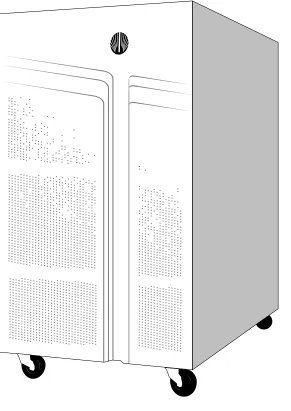
The Auspex NetServer provides highly responsive network file access and balanced compute service to many users on multiple networks. With a unique Functional Multiprocessor® (FMP®) architecture, the NetServer delivers high-speed network I/O performance. The NetServer’s scalable FMParchitecture and storage subsystems make it capable of operating efficiently under a variety of conditions and workloads. Figure 1-1 illustrates the NS 7000 Model 150 and Model 250 Series NetServer.
This chapter covers the following sections:
▲ Disk Subsystems
▲ Numbering Conventions
1-2 ▲ Overview ▲ NS 7000 Model 150/250 Series Hardware Manual
[image:18.612.126.417.77.488.2]USPEX
A
NS 7000 Model 150/250 Series Hardware Manual ▲ Overview ▲ 1-3
Table 1-1 lists the hardware features.
Table 1-1. NetServer hardware features
System architecture ▲ Functional Multiprocessor architecture with dedicated processors for network, file, UNIX, and storage processing.
▲ Host Processor that includes an Mbus-based, 90-MHz or 125-MHz Superscalar SPARC processor with up to 384 MB of memory. The Host Processor provides one SCSI, two serial, and three SBus connections (two masters and one slave).
▲ Optional nonvolatile Write Accelerator for improved NFS write-operation performance.
Enhanced VME backplane ▲ 4-slot enhanced VME backplane for connecting dedicated processor boards. The VME transfer speed is up to 100 MB per second between Network Processor IV (NP IV), Network Processor III (NP III), and Storage Processor V (SP V) boards, and up to 55 MB per second between all other NP and SP board combinations.
Subsystems ▲ High-performance storage subsystems: disk, tape, and CD-ROM drives are organized in racks of seven drives, with one rack in the base cabinet and two racks in each optional expansion cabinet (up to two expansion cabinets supported).
▲ Auto-configured SCSI ID that allows drives to be added in any drive slot without having to change the SCSI ID settings.
▲ Tape storage devices that can be attached to the NetServer through the HP or SP (refer to the Storage Peripherals Manager’s Guide for more information).
▲ Drives that can be hot-plugged; that is, removed or inserted while the NetServer is powered on.
Network connections ▲ Connections for 10Base-T and 100Base-T Ethernet, FDDI, and ATM.
1-4 ▲ Overview ▲ NS 7000 Model 150/250 Series Hardware Manual
USPEX
A
Figure 1-2 illustrates the hardware implementation of the NetServer Functional
[image:20.612.53.477.134.653.2]Multiprocessing® architecture. For a more detailed description of the systems operation, refer to the System Manager’s Guide.
Figure 1-2. FMP architecture
Network Connection: Ethernet, FDDI, ATM
6 Independent SCSI Channels
FMP I/O Backplane
UNIX Memory 32–384 MB
CPU MVIC
UNIX
SBus
I/O Cache Memory 64–256 MB CPU CPU Protocols Files Network Processor SBus
NS 7000 Model 150/250 Series Hardware Manual ▲ Overview ▲ 1-5
Processor Board Configuration
[image:21.612.135.561.136.685.2]Table 1-2 lists the processor board configuration options supported by Version 1.9 software for the NS 7000 150/250 Series NetServers.
Table 1-2. Processor board configuration
Processor board
Minimum configuration
Maximum
configuration Comments
Host Processor (HP VIII)
1 1 The HP VIII includes a 125-MHz SPARC processor and supports up to 384 MB of onboard dynamic RAM.
The HP also provides SCSI support for tape storage devices.
Network Processor (NP IV, NP III, NP II)
1 2 The NP supports 10Base-T Ethernet, 100Base-T Ethernet, FDDI, ATM, or combinations of these interfaces. For more information on supported interfaces, refer to Table 2-3 on page 2-13.
Each NP supports 64–256 MB of memory for protocol processing, file processing, and I/O cache memory.
Storage Processor (SP V, SP IV)
1 1 The SP V board supports the Write Accelerator III and II, which have 8 and 2 MB of cache memory, respectively. The SP IV board supports the Write
Accelerator I, which has 1 MB of cache memory.
The SP supports disk, tape, and CD-ROM drives in any combination.
1-6 ▲ Disk Subsystems ▲ NS 7000 Model 150/250 Series Hardware Manual
USPEX
A
Disk Subsystems
The maximum drive configuration requires one base cabinet, two expansion cabinets, and one tape storage device.
The base cabinet consists of one drive rack, holding up to 7 drives. Each expansion cabinet consists of two drive racks, holding up to 14 drives.
NS 7000 Model 150/250 Series Hardware Manual ▲ Numbering Conventions ▲ 1-7
Numbering Conventions
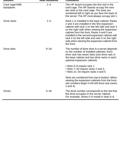
[image:23.612.136.554.153.693.2]Table 1-3 describes the numbering conventions used to identify the various elements of the NetServer’s scalable design.
Table 1-3. Numbering conventions
Element How numbered Comments
Card cage/VME backplane
1–4 The HP board occupies the first slot in the card cage. The NP boards occupy the next two slots in the card cage. The slots are numbered left to right as you face the back of the server. The HP must always occupy slot 1.
Drive racks 1–5 Rack 1 is installed in the base cabinet. Racks 2 and 3 are installed in the first expansion cabinet with rack 2 on the left side and rack 3 on the right side when viewing the expansion cabinet from the front. Racks 4 and 5 are installed in the second expansion cabinet with rack 4 on the left side and rack 5 on the right side when viewing the expansion cabinet from the front.
Drive slots 0–34 The number of drive slots in a server depends on the number of installed cabinets. Each drive rack has seven slots (one drive rack in the base cabinet and two drive racks in each optional expansion cabinet):
• Slots 0–6 require rack 1.
• Slots 7–20 require racks 2 and 3. • Slots 21–34 require racks 4 and 5.
Slots are numbered from top to bottom. When viewing the expansion cabinets from the front, slot numbers begin in the left drive rack (racks 2 and 4).
1-8 ▲ Environmental Requirements ▲ NS 7000 Model 150/250 Series Hardware Manual
USPEX
A
Environmental Requirements
Operate the NetServerin a temperature-controlled, contaminant-free atmosphere within the recommended levels of humidity. Table 1-4 lists the necessary environmental
conditions for the NetServer.
Note: The NetServer can operate at an altitude of up to 3,000 m (10,000 ft.). However, the maximum operating temperature at an altitude between 2,150 m (7,000 ft.) and 3,000 m (10,000 ft.) is 30° C (86° F).
Space Requirements
Place the NetServer base cabinet in a location no less than two feet from the nearest wall or other equipment. Two feet of clearance allows easy access to the front and back of the server and permits adequate air circulation around the equipment.
If your server includes one or two expansion cabinets, you must allow enough space at the installation site for the base cabinet and the expansion cabinets to sit side by side,
approximately two inches apart. Allow space to easily open the front and back doors of each cabinet.
Table 1-5 gives the dimensions of theNetServer base cabinet and optional expansion cabinets. The weights shown are calculated with no drives installed, and increase as additional drives are added.
Table 1-4. Environmental requirements
Minimum Maximum
Operating temperature 5° C (40° F) 40° C (104° F)
Storage temperature 0° C (32° F) 65° C (150° F)
Operating altitude 0 m (0 ft.) 2,150 m (7,000 ft.)
Storage altitude 0 m (0 ft.) 12,000 m (40,000 ft.)
Operating humidity (noncondensing at 40° C)
20% 80%
Nonoperating humidity (noncondensing at 40° C)
10% 90%
Audible noise N/A 60 dBA
Table 1-5. Base cabinet and expansion cabinet dimensions
Base cabinet Expansion cabinet
Height 77 cm (30 inches) 77 cm (30 inches)
Width 41 cm (16 inches) 41 cm (16 inches)
Depth 82 cm (32 inches) 82 cm (32 inches)
NS 7000 Model 150/250 Series Hardware Manual ▲ Electrical Requirements ▲ 1-9
Electrical Requirements
Caution: If you have expansion cabinets connected to the NetServer, each expansion cabinet must be powered from a different circuit than the NetServer.
The NetServer requires an electrical power source that is free of surges and must be
adequately grounded to protect it from electrostatic interference during operation. Maintaining proper environmental humidity also helps reduce the risk of electrostatic damage.
The power supply shipped with the server can accommodate a fully configured system. Table 1-6 and Table 1-7 list the electrical power requirements and input specifications.
Table 1-6. Electrical power requirements
Base cabinet (7 drives) Each expansion cabinet (14 drives)
705 W .705 KVA 2,410 BTUs/Hour
410 W .410 KVA 1,400 BTUs/Hour
Table 1-7. Electrical input specifications
Input Power Supply
Nominal input voltage range 100–240 VAC
Operating input voltage range 90–264 VAC
Current rating 6-3 A
Input service rating 15 A
Frequency 50–60 ±3 Hz
Inrush current 40 A peak max
Efficiency >75% typical
Power factor >.96 (115 VAC)
Turn-on time DC power = 1 second
Electromagnetic Immunity (EMI) filter (conducted)
FCC and VDE Level A
Total Harmonic Distortion Nominal line (110 V) under 6%
1-10 ▲ Electrical Requirements ▲ NS 7000 Model 150/250 Series Hardware Manual
USPEX
A
Power Cable Configurations
There are two power cable configurations for the NetServer.
North American
The North American configuration is shipped with an 18-3 gauge power cable that has a molded wall plug. The wall receptacle for this configuration must be on a circuit with a minimum capacity of 15 amps.
International (except Canada and Mexico)
NS 7000 Model 150/250 Series Hardware Manual ▲ Installation Overview ▲ 1-11
Installation Overview
This section provides an overview of installation procedures required to set up your NetServer. For detailed information, refer to the chapter listed with each procedure.
Caution: To prevent electrostatic damage to the server, always wear the antistatic wrist strap when working with electrostatic-sensitive equipment.
Unpacking the base cabinet
1. Unpack the NetServer (Chapter 2). 2. Lock the four casters (Chapter 2).
3. With power set to OFF, plug the power cable into a grounded outlet (Chapter 3).
Unpacking expansion cabinets
1. Unpack each expansion cabinet (Chapter 2).
2. Connect the expansion cabinets to the base cabinet (Chapter 3). 3. Lock the four wheels on each expansion cabinet (Chapter 2).
4. With power set to OFF, plug the power cable from each expansion cabinet into a separate grounded outlet (Chapter 3).
5. Connect the SCSI cables from the expansion cabinets to the base cabinet (Chapter 3).
Setting up your system
1. Connect the console to the Host Processor in the base cabinet (Chapter 3). 2. Attach the NetServer to your network (Chapter 3).
3. Install the drives shipped with your system with the root drive occupying slot 0, which is the top slot in the base cabinet (Chapter 3).
Powering on the NetServer
1. Power on the system console (Chapter 4).
NS 7000 Model 150/250 Series Hardware Manual ▲ About This Chapter ▲ 2-1
2
Unpacking and Setting Up
the System
About This Chapter
This chapter provides instructions for unpacking and setting up the NetServer base cabinet and expansion cabinets and includes information to help you familiarize yourself with the NetServer’s components.
This chapter covers the following sections:
▲ Unpacking the NetServer ▲ Locking the Casters
▲ Opening the Cabinet Doors
▲ Basic Components
▲ NetServer Base Cabinet Subassemblies ▲ Expansion Cabinet Subassemblies
▲ Card Cage Components
2-2 ▲ Unpacking the NetServer ▲ NS 7000 Model 150/250 Series Hardware Manual
USPEX
A
Unpacking the NetServer
This section provides unpacking instructions for the NetServer base cabinet and expansion cabinets. Instructions for unpacking and installing other NetServer components appear in Chapter 3 in the sections “Connecting the System Console to the NetServer” “Installing Drives” and “Attaching a SCSI Device to the HP”.
Tools
▲ Knife to open the packing boxes containing drives and accessories ▲ Wire cutter to cut tie-wraps (cut only red tie-wraps)
▲ Adjustable wrench to remove wooden lag bolts ▲ Band cutter to open the shipping container
To unpack the NetServer
1. Place the NetServer base cabinet on the site prepared for it.
For easy access and proper air circulation, make sure there is at least two feet of clearance between the server and any wall or other equipment (except the expansion cabinet). Also, make sure there is an appropriate wall receptacle within six feet of the server.
2. Use a band cutter to cut and remove the straps that secure the wooden ramp located on top of the server. You use this ramp in step 6.
3. Remove the protectors from each corner of the server.
4. Remove the corrugated sleeve from the base pallet by sliding it up and off the unit. To avoid damaging the unit, do not cut the corrugated sleeve with a knife.
5. Use an adjustable wrench to remove the two lag bolts from the base pallet and remove the wooden stop marked “FRONT.”
6. Place the ramp (the panel removed in step 2) in position next to the edge of the pallet, adjacent to the front panel of the server.
7. Carefully roll the server down the ramp to the floor.
Caution: Be sure that the high end of the ramp is slightly lower than the base of the crate, or theserver’s casters may move the ramp out of position as you roll it onto the ramp.
8. Remove the plastic packing material from the server by sliding it up and off the unit. To avoid damaging the unit, do not cut the plastic packing material with a knife. 9. Roll the server to the site prepared for it.
10. If your NetServer includes expansion cabinets: a. Repeat steps 1 through 8.
NS 7000 Model 150/250 Series Hardware Manual ▲ Locking the Casters ▲ 2-3
Note: If the surface of the NetServer becomes marked or smudged, use a nonabrasive stainless-steel cleaner to clean the surface.
This concludes the instructions for unpacking the NetServer and expansion cabinets. Proceed to section “Locking the Casters” on page 2-3.
Locking the Casters
Each cabinet has casters so that you can easily roll it to its permanent site. Once you have rolled the server to its permanent site, lock the casters. The procedure is the same for both the base cabinet and expansion cabinet.
To lock the casters
1. Locate the four casters. There is one caster underneath each corner of the cabinet. 2. On each caster, turn the locking lever until the lever is horizontal (see Figure 2-1). This
prevents the system from rolling and potentially disconnecting cables.
Figure 2-1. Locking the casters
This concludes the procedure for locking the casters.
Opening the Cabinet Doors
The NetServer doors are unlocked with a system key. Once unlocked, you can open and close the doors without a key.
Two duplicate keys are tie-wrapped to the NetServer power cable. The keys open both the front and back doors of the cabinet. If your NetServer includes expansion cabinets, the same keys also open their front and back doors.
2-4 ▲ Basic Components ▲ NS 7000 Model 150/250 Series Hardware Manual
USPEX
A
Basic Components
This section describes the basic components shipped with your NetServer. After unpacking the NetServer, make sure you have the following:
▲ Disk drives (one minimum), packed separately in a foam-padded box, to install in the
base cabinet
▲ CD-ROM (one minimum) and optional 8-mm tape drives to install in the base cabinet,
packed separately in a foam-padded box
▲ Documentation set, including:
- NS 7000 Model 150/250 Series Hardware Manual (this manual) - System Manager's Guide
- System Manager’s Quick Reference - Command Reference Guide
- Software release note
▲ System console (shipped in a separate carton)
▲ One 25-foot null-modem RS-232C console cable (shipped in a separate carton)
Refer to Figure 2-2 on page 2-5 to identify system cables shipped with your NetServer. Some components, such as the SCSI cable that connects the drives in the base cabinet to the Storage Processor are already installed within the server and should not be removed. Instructions for connecting cables appear in Chapter 3 in the sections “Grounding the NetServer,” “Connecting the System Console to the Server,” “Attaching a SCSI Device to the Host Processor,” and “Connecting the NetServer to the Network.”
If you ordered an expansion cabinet, make sure you have the following:
▲ Expansion cabinet connection kit
▲ Disk drives, packed separately in a foam-padded box, to install in the expansion
cabinet
▲ Any additional tape or CD-ROM drives, packed separately in a foam-padded box, to
install in the expansion cabinet
▲ One power cable (installed inside the expansion cabinet and secured with red
tie-wraps)
Each expansion cabinet accepts the same type of disk, tape, and CD-ROM drives as the base cabinet.
The following cables are included in each expansion cabinet (installed within the system and secured with red tie-wraps):
▲ One power cable
▲ Two 5-foot SCSI drive cables that connect the drives in the expansion cabinet to the
Storage Processor board in the base cabinet
NS 7000 Model 150/250 Series Hardware Manual ▲ Basic Components ▲ 2-5 Figure 2-2. System cables
Power cable (connector provided
on North American systems only)
Console cable SCSI cable
2-6 ▲ NetServer Base Cabinet Subassemblies ▲ NS 7000 Model 150/250 Series Hardware Manual
USPEX
A
NetServer Base Cabinet Subassemblies
The base cabinet contains the following subassemblies:▲ Card cage chassis with four slots ▲ Disk drive rack
▲ Power systems unit (PSU)
Figures 2-3 and 2-4 show the front and the back views of the base cabinet with the subassemblies labeled.
Figure 2-3. Base cabinet subassemblies (front view)
System chassis
Drive (in carrier)
Backplane panel
Air filter Door panel
Wrist strap jack
Empty drive slot
NS 7000 Model 150/250 Series Hardware Manual ▲ NetServer Base Cabinet Subassemblies ▲ 2-7 Figure 2-4. Base cabinet subassemblies (back view)
DIAG READY RESET RUN
DIAG NORM
DIAG LEDS
SCSI
TTYB
TTYA
Drive rack
Antistatic wrist strap Wrist strap jack Card cage Fans
2-8 ▲ Expansion Cabinet Subassemblies ▲ NS 7000 Model 150/250 Series Hardware Manual
USPEX
A
Expansion Cabinet Subassemblies
The expansion cabinet contains the following subassemblies:▲ Two disk drive racks ▲ PSU
Figures 2-5 and 2-6 show the front and back views of the expansion cabinet.
Figure 2-5. Expansion cabinet (front view)
System chassis
Door panel
Drive (in carrier)
Empty drive slot
NS 7000 Model 150/250 Series Hardware Manual ▲ Expansion Cabinet Subassemblies ▲ 2-9 Figure 2-6. Expansion cabinet (back view)
Drive racks
2-10 ▲ Card Cage Components ▲ NS 7000 Model 150/250 Series Hardware Manual
USPEX
A
Card Cage Components
The NetServer card cage houses the following VME-compatible printed circuit boards:
▲ HP (one)
▲ NP (up to two) ▲ SP (one)
Each of these boards, their functions, and the minimum and maximum configurations are described in the following sections.
Table 2-1 lists the slot assignments for each processor board type. The slots are numbered from left to right when viewed from the back of the cabinet.
Host Processor
The NetServer has one HP VIII or HP VII board with several features:
▲ 125-MHz (HP VIII) or 90-MHz (HP VII) SPARC processor.
▲ Two or four Single In-Line Memory Modules (SIMMs) of 16–128 MB each for up to
384 MB of host memory (see Table 2-2).
Table 2-1. Processor board slot assignments
Slot number Board assignment
1 Host Processor
2 Network Processor
3 Network Processor (if present)
[image:38.612.55.476.457.670.2]4 Storage Processor
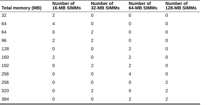
Table 2-2. HP memory module configurations
Total memory (MB)
Number of 16-MB SIMMs Number of 32-MB SIMMs Number of 64-MB SIMMs Number of 128-MB SIMMs
32 2 0 0 0
64 4 0 0 0
64 0 2 0 0
96 2 2 0 0
128 0 0 2 0
160 2 0 2 0
192 0 2 2 0
256 0 0 4 0
256 0 0 0 2
320 0 2 0 2
NS 7000 Model 150/250 Series Hardware Manual ▲ Card Cage Components ▲ 2-11
Caution: The HP does not support mixing SIMMs. HP SIMMs must be installed in pairs of 16, 32, 64, or 128 MB.
▲ Support for up to three SBus cards, including three single, one double and one single,
or one triple SBus card.
Note: Contact your authorized Auspex service representative for information on supported SBus cards.
▲ Support for serial connections on ttya and ttyb.
▲ Integrated Mbus design which allows future upgrades to the HP CPU. ▲ Support for up to seven Sun-supported SCSI devices on one SCSI port. ▲ Support for tape storage devices.
2-12 ▲ Card Cage Components ▲ NS 7000 Model 150/250 Series Hardware Manual
USPEX
A
Figure 2-7. HP front panel connectors
DIAG READY RESET RUN DIAG NORM DIAG LEDS SCSI TTYB TTYA
SCSI port. The SCSI port supports up to seven daisy-chained SCSI devices. Refer to “Attaching a SCSI Device to the Host Processor” on page 3-27 for a list of supported devices. Tape storage devices are also supported from the SCSI port. Refer to the Storage
Peripherals Manager’s Guide for supported devices.
Reset switch. This switch resets the system processor boards without power cycling the NetServer using the main power switch.
Caution: Follow the shutdown procedures described in “Shutting Down the NetServer” on page 4-15 before you reset or power off the system.
Diagnostic LEDs. When the NetServer is running in diagnostic mode, the state of these eight LEDs represents a specific diagnostic test running on the HP. When the operating system is running, the LEDs light in an oscillating pattern, the speed of which is determined by the CPU load— the slower the speed, the higher the load.
TTYB serial port. TTYB is available for connecting a modem or other serial device.
TTYA serial port. TTYA supports the console terminal. Refer to “Connecting the System Console to the Server” on page 3-10.
SBus ports. The HP has three SBus ports: two masters and one slave. The HP supports three single, one double and one single, or one triple SBus board. Tape storage devices are also supported from the SBus port. Refer to the Storage Peripherals Manager’s Guide for supported devices. For information on compatible SBus boards, contact your authorized Auspex service representative.
Status indicator LEDs. The DIAG LED lights indicating the system is performing power-on self tests. The READYLED lights indicating the system successfully completed self tests.
Diagnostic switch. Set this switch to the NORM position before you power on the NetServer. Setting this switch to DIAG puts the NetServer in diagnostic mode automatically after you power on or reset the system. (Provided for authorized service personnel only.)
NS 7000 Model 150/250 Series Hardware Manual ▲ Card Cage Components ▲ 2-13
Network Processor
The NetServer has one to two NP IV, NP III, or NP II boards, supporting either Ethernet, FDDI, ATM, or combinations of these interfaces.
Note: ATM and 100Base-T Ethernet require optional software (refer to the optional products documentation provided on the Auspex Premier Software Series CD-ROM for more information).
Table 2-3 lists examples of supported network interfaces for the NP boards.
Each NP has 64–256 MB of memory for protocol processing, file processing, and I/O cache memory. The NP III and NP IV have four or eight SIMMs of either 16 MB or 32 MB each. Memory must be installed in groups of four SIMMs of the same capacity. The NP II has one or two memory modules of either 64 MB or 128 MB each. Refer to Table 2-4 for supported memory configurations.
Table 2-3. Supported network interfaces
Number and type of interfaces
supported NP II NP III NP IV
2-Enet Y Y Y
6-Enet Y Y Y
1 FDDI, 4-Enet Y Y Y
1 ATM, 4-Enet Y Y Y
2 ATM, 2-Enet Y Y Y
1 100BT, 4-Enet Y Y Y
2 100BT, 2-Enet Y Y Y
3 FDDI N Y Y
3 ATM N Y Y
3 Half-duplex100BT N Y Y
3 Full-duplex 100BT N Y Y
2 Full-duplex 100BT, 2-Enet Y Y Y
1 Full-duplex 100BT, 4-Enet Y Y Y
1 Full-duplex 100BT, 1 FDDI Y Y Y
Table 2-4. NP memory configurations
NP IV/III NP II
Total memory (MB) Number of 16-MB SIMMs Number of 32-MB SIMMs Number of 64-MB modules Number of 128-MB modules
64 4 0 1 0
128 8 0 2 0
128 0 4 0 1
192 4 4 1 1
2-14 ▲ Card Cage Components ▲ NS 7000 Model 150/250 Series Hardware Manual
USPEX
A
The NP III and NP IV have a VME transfer speed of up to 100 MB per second when operating in conjunction with an SP V board. The NP II has a VME transfer speed of up to 55 MB per second when operating in conjunction with either an SP IV or an SP V board.
Storage Processor
The NetServer uses one SP IV or SP V board, each with six parallel SCSI channels for disk, tape, and CD-ROM drives.
The SP IV has a VME transfer speed of up to 55 MB per second when operating in conjunction with either an NP II, NP III, or NP IV. The SP V has a VME transfer speed of up to 100 MB per second when operating in conjunction with an NP III or NP IV.
Figure 2-8 shows a card cage configuration with network connections.
Figure 2-8. System processors
DIAG READY RESET RUN
DIAG NORM
DIAG LEDS
SCSI
TTYB
TTYA
Network Processor (FDDI)
Storage Processor Host Processor
Slot 1 Slot 2 Slot 3 Slot 4
NS 7000 Model 150/250 Series Hardware Manual ▲ About This Chapter ▲ 3-1
3
Installation
About This Chapter
This chapter describes installing NetServer components. It does not describe installing card cage components, such as processor boards and memory modules.
This chapter covers the following sections:
▲ Grounding the NetServer
▲ Installing the Antistatic Wrist Strap ▲ Attaching Expansion Cabinets
▲ Connecting SCSI Cables from the Expansion Cabinet ▲ Connecting the System Console to the NetServer ▲ Connecting the NetServer to the Network ▲ Installing Drives
▲ Attaching a SCSI Device to the HP
Note: The NetServer has been configured at the factory to match your order; however, an additional processor board, processor board memory, and drives are available as optional equipment. This manual does not provide
instructions for installing any card cage components, such as processor boards and memory modules. If you are adding or replacing a board or module in your NetServer, contact your authorized Auspex service representative for assistance.
3-2 ▲ Grounding the NetServer ▲ NS 7000 Model 150/250 Series Hardware Manual
USPEX
A
Grounding the NetServer
This section provides instructions for grounding the base cabinet. You must plug in the power cord for each cabinet to create a ground path for the antistatic wrist strap.
Warning: The wiring at your site must provide for ground fault protection.
Tools
▲ Knife to open the packing boxes containing drives and accessories ▲ Wire cutter to cut tie-wraps (cut only red tie-wraps)
▲ 3/16-inch flat-head screwdriver to attach the console cable
1. Locate the main power switch on the PSU below the back door of the base cabinet. Set the switch to OFF (O) (see Figure 3-1).
Figure 3-1. Main power switch (back view of NetServer)
2. If your server includes expansion cabinets, locate the main power switch on the PSU below the back door of each expansion cabinet. Set this switch to OFF (O)
(see Figure 3-1).
3. Locate the power cable for each cabinet.
On the base cabinet, the cable is hanging on the left side of the cabinet, secured with red tie-wraps. On the expansion cabinet, the cable is coiled on top of the panel covering the power supply.
4. Cut the red tie-wraps to release the power cable for each cabinet.
5. After ensuring that power to the system is off, route each power cable to a separate grounded outlet. Plug each cable into a receptacle (each outlet must be on a circuit with a minimum capacity of 15 amps).
Power plug Power systems unit
Power cable
NS 7000 Model 150/250 Series Hardware Manual ▲ Grounding the NetServer ▲ 3-3
Caution: Do not power on the server at this time. You connected the power cable only to provide a ground path for the antistatic wrist strap. Do not power on the server until instructed to do so later in this manual.
3-4 ▲ Installing the Antistatic Wrist Strap ▲ NS 7000 Model 150/250 Series Hardware Manual
USPEX
A
Installing the Antistatic Wrist Strap
To prevent electrostatic damage to the NetServer, always wear the antistatic wrist strap when you come in contact with electrostatic-sensitive equipment.
Note: The wrist strap cannot prevent electrostatic damage to system components until the power cable is plugged into a grounded power receptacle. Refer to the previous section for information on grounding the server.
The base cabinet has two wrist strap jacks, one below the card cage in the back of the cabinet and one above the drive rack area in the front of the cabinet. One wrist strap is provided with the base cabinet (attached to the rear jack).
Note: The expansion cabinets do not have wrist strap jacks. Use the base cabinet wrist strap for both the base cabinet and expansion cabinets.
1. Cut the red tie-wraps holding the wrist strap to the hook located next to the rear jack. 2. To use the wrist strap, remove the strap from the hook and slide it around your wrist,
as shown in Figure 3-2.
Note: When you are not using the wrist strap, remember to hang it on the hook.
3. As you move between the front and back of the system, you can unplug the wrist strap from one jack and plug it into the other.
Figure 3-2. Antistatic wrist strap
This concludes the procedure for installing the antistatic wrist strap. If you wish to add expansion cabinets, proceed to section “Attaching Expansion Cabinets” on page 3-5.
Wrist strap jack
NS 7000 Model 150/250 Series Hardware Manual ▲ Attaching Expansion Cabinets ▲ 3-5
Attaching Expansion Cabinets
After setting up the base cabinet and positioning the expansion cabinets, connect them using the procedures in this section.
A kit is packaged with the expansion cabinet for attaching the expansion cabinet to the base cabinet. To attach the cabinets, you must install U-shaped brackets.
Expansion Kit Components
Attaching one expansion cabinet requires two U-shaped brackets (one in the front and one in the back) and eight screws. The expansion kit contains the necessary parts for attaching two expansion cabinets to the base cabinet. Table 3-1 lists the parts contained in the kit; inspect the contents to make sure all items in the table are included with the expansion kit received. If a part is missing, contact Auspex Customer Service for replacement.
Installing the U-shaped Brackets
The U-shaped brackets attach to the inside of the rails on the sides of the cabinets. The following procedure leads you through the installation.
Caution: This procedure assumes you are installing an expansion cabinet during a first-time installation. If the base cabinet is already installed and operating, power down the NetServer before attaching the expansion cabinet.
To install the U-shaped brackets
1. Position the expansion cabinet next to the base cabinet so that the sides are approximately 3 inches (75 mm) apart.
When viewed from the front, the first expansion cabinet should be to the right of the base cabinet. The second expansion cabinet should be to the left of the base cabinet. 2. Open the base cabinet and expansion cabinet front doors.
3. Put on the antistatic wrist strap.
4. Remove the air filter from its holder in the base and expansion cabinet to expose the screw holes on the side.
5. Slide your hand along the bottom of the side rails to locate the bracket attachment openings.
6. Push the top of the bracket up into the opening on both cabinets (see Figure 3-3).
Table 3-1. Expansion kit contents
Quantity Part Part number
4 3-inch (75 mm)
U-shaped bracket
52-0339
16 4x0.7x8-mm
screws
3-6 ▲ Attaching Expansion Cabinets ▲ NS 7000 Model 150/250 Series Hardware Manual
USPEX
A
Figure 3-3. Lining up the U-shaped bracket
7. Push the bracket forward until it locks into position (see Figure 3-4).
NS 7000 Model 150/250 Series Hardware Manual ▲ Attaching Expansion Cabinets ▲ 3-7
8. Secure the front bracket with the four screws provided (see Figure 3-5).
Figure 3-5. Attaching the U-shaped bracket
9. Replace the air filter removed in step 4. 10. Close the front doors.
11. Move to the back of the cabinet, and open the doors. 12. Install the back bracket by repeating steps 5 through 8.
Because of the location of the power supply, there is limited room for inserting the screws into the back bracket.
13. Start the screws with your fingers, then tighten them down with a screwdriver. 14. Close the back doors.
3-8 ▲ Connecting SCSI Cables from the Expansion Cabinet ▲ NS 7000 Model 150/250 Series Hardware Manual
USPEX
A
Connecting SCSI Cables from the Expansion
Cabinet
Optional expansion cabinets are available from Auspex. Each expansion cabinet is shipped with two SCSI cables.
To connect SCSI cables from expansion cabinet
1. Open the back doors of the base and expansion cabinets.
2. Locate the SCSI drive cables tie-wrapped to the left side of each expansion cabinet inside the back door.
3. Cut the red tie-wraps securing the cables.
4. Route the free end of each SCSI cable out the back of the expansion cabinet and into the back of the base cabinet. Avoid bending the cable in a tight radius. Leave a small amount of slack in the cable inside the expansion cabinet.
5. Attach the cable to the SP connector indicated on the label affixed to the cable. Tighten the two jack screws located on the SCSI cable connector until the connector is firmly seated to the SP. Gently pull the cable to verify that the cable is connected properly. Figure 2-2 on page 2-5 shows the SCSI cable connector.
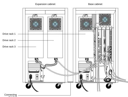
Table 3-2 lists the cable connections from each drive rack to the SP board. Rack 1 is located in the base cabinet. Racks 2 and 3 are located in the first expansion cabinet. Racks 4 and 5 are located in the second expansion cabinet. When viewing the first and second expansion cabinets from the back, racks 2 and 4 are on the right side of each cabinet and racks 3 and 5 are on the left side of each cabinet.
Note: When viewing the server from the back, the first expansion cabinet is located to the left of the base cabinet and the second expansion cabinet, if present, is located to the right of the base cabinet.
[image:50.612.55.233.473.574.2]* SP connectors are labeled from the bottom connector, J1, to the top connector, J6.
Table 3-2. SP cable connections from each drive rack
Drive rack SP connector*
Rack 1 J1
Rack 2 J2
Rack 3 J3
Rack 4 J4
NS 7000 Model 150/250 Series Hardware Manual ▲ Connecting SCSI Cables from the Expansion Cabinet ▲ 3-9
Figure 3-6 shows one expansion cabinet connected to a base cabinet.
Figure 3-6. Back view of connected cabinets
This concludes the procedure for connecting the SCSI drive cables from the expansion cabinet. Proceed to section “Connecting the System Console to the NetServer” on page 3-10.
DIAG READY RESET RUN DIAG NORM
DIAG LEDS
SCSI
TTYB
TTYA
Drive rack 1
Drive rack 2
Drive rack 3
Connecting bracket
3-10 ▲ Connecting the System Console to the NetServer ▲ NS 7000 Model 150/250 Series Hardware Manual
USPEX
A
Connecting the System Console to the NetServer
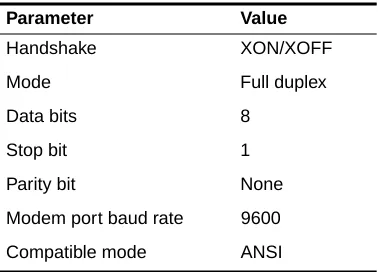
This section explains how to connect the system console to the NetServer. Auspex provides an ANSI-compatible DEC VT510 terminal with each NetServer for use as a system console. If you wish to use another type of terminal as a console, call your authorized Auspex service representative for information.Table 3-3 lists the key setup parameters necessary to configure any console for use with the NetServer. The setup parameters are preconfigured for consoles purchased from Auspex.
To connect the DEC VT510 console to the server
1. Place the packing box containing the console near the server.
2. Remove the console and its associated components from the packing box.
3. Attach the keyboard and power cable to the console, as described in the console’s user manual.
Caution: Do not power on the console at this time.
4. Remove the console cable from its packing box.
5. Open the back door of the base cabinet, and put on the antistatic wrist strap.
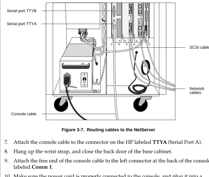
[image:52.612.55.244.201.337.2]6. Route one end of the console cable to the back of the NetServer cabinet, as shown in Figure 3-7.
Table 3-3. Console setup parameter values
Parameter Value
Handshake XON/XOFF
Mode Full duplex
Data bits 8
Stop bit 1
Parity bit None
Modem port baud rate 9600
NS 7000 Model 150/250 Series Hardware Manual ▲ Connecting the System Console to the NetServer ▲ 3-11 Figure 3-7. Routing cables to the NetServer
7. Attach the console cable to the connector on the HP labeled TTYA (Serial Port A). 8. Hang up the wrist strap, and close the back door of the base cabinet.
9. Attach the free end of the console cable to the left connector at the back of the console labeled Comm 1.
10. Make sure the power cord is properly connected to the console, and plug it into a grounded power outlet.
11. Power on the console.
This concludes the procedure for connecting the system console to the NetServer. Proceed to section “Connecting the NetServer to the Network” on page 3-12.
Note: If you did not purchase your console from Auspex, configure the console as described in Appendix C.
TTYB
TTYA
Serial port TTYB
Serial port TTYA
Console cable
SCSI cable
3-12 ▲ Connecting the NetServer to the Network ▲ NS 7000 Model 150/250 Series Hardware Manual
USPEX
A
Connecting the NetServer to the Network
This section provides instructions for connecting the NetServer to your network. It assumes the appropriate network is already installed at your site.
Note: Auspex does not supply network cables. For information on network cables, refer to Appendix B.
The NetServer supports NFS file service through Ethernet, FDDI, and ATM networks. The FDDI networks supported are fiber dual-attach station (DAS) and both fiber and MLT-3 single-attach station (SAS). The Ethernet networks supported are 10Base-T and 100Base-T.
Note: ATM and 100Base-T require optional software. Refer to the
documentation provided on the Auspex Premier Software Series CD-ROM for more information on these optional products.
Connecting Network Cables to the NetServer
To connect the network cables to the NetServer base cabinet
1. Open the back door of the base cabinet.
2. Attach the antistatic wrist strap to your wrist to protect against possible static damage to the equipment.
3. Route each network cable to the back of the NetServer, being careful not to bend the cable in a tight radius (see Figure 3-7 on page 3-11).
4. Attach each network cable to the appropriate connector on the NP boards. Leave a small amount of slack in the cable inside the cabinet.
Note: The FDDI-SAS port for a fiber connection is a single-attach station of “Type S.” Connect the FDDI-SAS only to a “Type M” FDDI concentrator port. The FDDI-DAS ports are a dual-attach station. You can connect directly to the primary and secondary FDDI rings or to “Type M” ports on two concentrators in a dual-homed configuration.
Note: The ATM connector uses a 155 MB-per-second multimode fiber cable with an SC-type connector, or UTP cable with a standard RJ45 connector. If your site uses ST-type ATM cabling, you need an ST-to-SC converter. 5. Hang up the wrist strap and close the back door of the base cabinet.
6. After powering on the NetServer as described in Chapter 4, you can test the connection between the NetServer and the network by running NSconfig.
Note: For more information on NSconfig, refer to your System Manager’s Guide.
This concludes the procedure for connecting network cables to the NetServer.
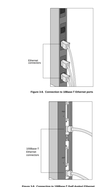
NS 7000 Model 150/250 Series Hardware Manual ▲ Connecting the NetServer to the Network ▲ 3-13 Figure 3-8. Connection to 10Base-T Ethernet ports
Figure 3-9. Connection to 100Base-T (half duplex) Ethernet ports
Ethernet connectors
PORT PORT
2
100Base-T Ethernet connectors
3-14 ▲ Connecting the NetServer to the Network ▲ NS 7000 Model 150/250 Series Hardware Manual
[image:56.612.145.380.85.359.2]USPEX
A
[image:56.612.151.377.395.674.2]Figure 3-10. Connection to 100Base-T (full duplex) ports
Figure 3-11. Connection to FDDI (fiber) ports
100Base-T Ethernet connectors
PORT
2
PORT
1
NS 7000 Model 150/250 Series Hardware Manual ▲ Connecting the NetServer to the Network ▲ 3-15 Figure 3-12. Connection to FDDI (MLT-3) ports
Figure 3-13. Connection to ATM (fiber) ports
MLT-3 connectors
ATM connectors
R
T
R
3-16 ▲ Connecting the NetServer to the Network ▲ NS 7000 Model 150/250 Series Hardware Manual
[image:58.612.146.367.79.362.2]USPEX
A
Figure 3-14. Connection to ATM (UTP) ports
ATM connectors
R
T
R
NS 7000 Model 150/250 Series Hardware Manual ▲ Connecting the NetServer to the Network ▲ 3-17 Figure 3-15. Location of network ports on mixed NP boards
NP (FDDI)
NP (Enet/FDDI)
NP (ATM)
R
T
R
T
NP (100Base-T)
MII
MII
MII
R
3-18 ▲ Connecting the NetServer to the Network ▲ NS 7000 Model 150/250 Series Hardware Manual
USPEX
A
Network Interface Numbering
Each NetServer network interface has a unique identifier within each type of connection: 10Base-T Ethernet, 100Base-T Ethernet (half and full duplex), FDDI, and ATM. These interface numbers are used when configuring the system software. Each numbering scheme is described as follows.
10Base-T Interfaces are numbered within the range from ae0 to aen
where 0 is the lower 10Base-T Ethernet port closest to the HP and n is the upper 10Base-T Ethernet port farthest from the HP.
100Base-T (half duplex) Interfaces are numbered within the range from afe0 to afen where 0 is the lower 100Base-T Ethernet port closest to the HP and n is the upper 100Base-T Ethernet port farthest from the HP.
100Base-T (full duplex) Interfaces are numbered within the range from ahme0 to ahmen where 0 is the lower 100Base-T Ethernet port closest to the HP and n is the upper 100Base-T Ethernet port farthest from the HP.
FDDI Interfaces are numbered within the range from afddi0 to
afddin where 0 is the lower FDDI port closest to the HP and n is the upper FDDI port farthest from the HP.
Note: In DAS configurations, only one port is assigned an interface number even though two ports exist on the FDDI-DAS board.
ATM Each port has two kinds of interfaces: one primary
interface (called the FORE IP interface), and four virtual interfaces. The primary interfaces are numbered within the range from afa0 to afan where 0 is the lower ATM port closest to the HP and n is the upper ATM port farthest from the HP. The virtual interfaces are numbered within the range from aqa0 to aqa15.
NS 7000 Model 150/250 Series Hardware Manual ▲ Connecting the NetServer to the Network ▲ 3-19 Figure 3-16. Example of network interface numbering
NP (FDDI-SAS/100BT
Full Duplex)
NP (Enet/100BT
Full Duplex)
NP (100BT Full Duplex)
MII
MII MII
MII
MII
Label location Label
location
afddi0 afddi0
ahme0 ae0 ae1
3-20 ▲ Connecting the NetServer to the Network ▲ NS 7000 Model 150/250 Series Hardware Manual
USPEX
A
Ethernet Addresses
Each 10Base-T and 100Base-T port has a unique Ethernet address assigned at Auspex Systems. At the top of each installed NP with Ethernet ports is a label that gives the serial number of the board and the Ethernet address for the interface located at the bottom of the board (for example, ahme0 in Figure 3-16). This address ends with 0. For 100Base-T full duplex, this numbering scheme continues up to the top interface which has a network address ending with 3.
All Auspex Ethernet addresses start with 00:00:3c.
Table 3-4 is an example of Ethernet network addresses for the Ethernet interfaces in Figure 3-16.
[image:62.612.55.229.244.326.2]* This address appears on the label
Table 3-4. Ethernet address numbering scheme for 100Base-T full duplex
Interface number Network address
ahme3 00:00:3c:99:99:03
ahme2 00:00:3c:99:99:02
ahme1 00:00:3c:99:99:01
NS 7000 Model 150/250 Series Hardware Manual ▲ Installing Drives ▲ 3-21
Installing Drives
The NetServer disk, tape, and CD-ROM drives are shipped separately. They must be unpacked and installed into the NetServer drive racks before the system can be used. Each drive rack can hold up to seven disk, tape, or CD-ROM drives. This section describes how to install disks shipped with your NetServer. For instructions on removing drives and information on possible drive configurations, refer to Appendix A.
Note: The NetServer supports up to 35 disk or CD-ROM drives with two additional tapes. Drive slot 0 in the base cabinet is reserved for the root disk drive, which contains the server’s operating system software. Use disk, tape, and CD-ROM drives specifically designed for use with your NetServer. You received a set of labels to attach to drives that you might install in your NetServer. Write down the slot number of the drive, as recognized by the system software, on each label. Put the extra labels away in a safe place. You need them when you expand your system.
Caution: To preserve data integrity, make sure the system is powered off throughout this procedure.
To install drives in the NetServer
1. Place the drive packaging within easy reach of the NetServer cabinet in which the drives will be installed.
2. Plug the antistatic wrist strap into the jack location above the drive rack area and wear the wrist strap to protect against electrostatic damage to the drives.
3. Use a knife to carefully open the box. Drives are packed in foam slots, in an antistatic wrapping.
4. Open the proper door of the NetServer to expose the drive rack slots.
3-22 ▲ Installing Drives ▲ NS 7000 Model 150/250 Series Hardware Manual
[image:64.612.179.349.86.411.2]USPEX
A
Figure 3-17. Base cabinet driveslot numbering
Slot 0
Slot 1
Slot 2
Slot 5
NS 7000 Model 150/250 Series Hardware Manual ▲ Installing Drives ▲ 3-23 Figure 3-18. First expansion cabinet drive slot numbering
Slot 14
Slot 15
Slot 16
Slot 19
Slot 20 Slot 18 Slot 17 Slot 7
Slot 8
Slot 9
Slot 12
Slot 13 Slot 11 Slot 10
3-24 ▲ Installing Drives ▲ NS 7000 Model 150/250 Series Hardware Manual
[image:66.612.171.340.82.413.2]USPEX
A
Figure 3-19. Second expansion cabinet drive slot numbering
5. Remove the root disk drive from its antistatic wrapping. The root disk drive has a root disk drive label located at the front of the drive carrier.
6. Place the root drive into the top slot of the base cabinet (slot 0), with the numbered label located on the right side of the drive handle.
Holding the drive by the handle and cradling it with your other hand, gently slide it into the slot until the small latch button on the right side of the drive carrier clicks into the hole in the drive slot. If this latch button obstructs the drive from sliding into the slot, depress the button on the right side of the drive handle to retract the button and complete the installation.
Caution: Do not slam the drives into the slots. This causes damage to the drives and connectors.
Refer to Figure 3-20 for an example of installing a drive. Slot 28
Slot 29
Slot 30
Slot 33
Slot 34 Slot 32 Slot 31 Slot 21
Slot 22
Slot 23
Slot 26
Slot 27 Slot 25 Slot 24
NS 7000 Model 150/250 Series Hardware Manual ▲ Installing Drives ▲ 3-25 Figure 3-20. Installing a drive
Drives install in only one direction. If the drive you are installing does not slide in easily and the latch does not click into place, remove the drive and try again. Make sure the drive is in the correct position with the release trigger to the right side of the handle.
7. Install the remaining drives in their slots. Use the labels provided with your cabinet to write down the drive slot number of the drives, as recognized by the system software. This concludes the procedure for installing drives in your NetServer. If you wish to attach a SCSI device to your NetServer, proceed to section “Attaching a SCSI Device to the HP” on page 3-26.
Drive label Drive rack
Drive
Release trigger Antistatic
Attaching a SCSI Device to the HP
This section describes how to attach a SCSI device to the NetServer. The SCSI port on a HP supports the standard SunOS device drivers. You can attach seven Sun-supported SCSI devices to this port.
Note: Devices attached to the HP SCSI port cannot be used as boot devices. Only Auspex devices attached to an SP are bootable devices. Auspex does not supply a SCSI cable for the HP SCSI port.
You must set the appropriate SCSI ID for each device attached to the HP, or