Electrical Supply System and Motors
Power Supply
The supply of electric power to an electrical load is called power supply. The main function of the power supply is to convert electric current from a source to the correct voltage, current and frequency to power the load. Electrical outlet, energy storage device such as batteries, fuel cells, generator, solar power converters are generally known as power sources.
Power supply is classified into different categories. In our subsequent sections, we will see what the different categories are.
DC Power Supply
Such type of supply supplies a constant DC voltage to the loads. It may deliver from a DC source or an AC source.
AC-DC Supply
AC energy can deliver DC power with the help of a rectifier, which converts the transformer output voltage to a varying DC voltage. The DC voltage passes through an electronic filter, which turns it into an unregulated DC voltage. There is also a register in series with the output to limit charging current and the final output power is fed to the load.
Switched Mode Power Supply (SMPS)
The main input is converted to DC voltage via rectifier and filter and then switched on and off at a high frequency (10 KHz- 1 MHz) by an electronic switch. It has a safety feature to protect the device and the user.
Linear Regulator
Linear regulator converts a varying DC voltage to a constant. There is a current limiting function to protect the power supply and load from overcurrent. It is independent of fluctuation in input voltage and loads impedance to provide a steady value.
AC Power Supply
AC power supply can be taken from the main supply transferred to the desired voltage with the help of step up and step down transformer. This supply is divided into a single-phase and a three-phase system.
A PPS provides remote control operation through an analog input or digital interface such as RS 232. The controlled properties include voltage, current and frequency (in case of AC).
Uninterruptible Power Supply
UPS has a feature to take power from two or more sources simultaneously. It is used as a backup supply as it takes over the load in dropout or failure condition of main supply. The process is so fast that the load never experiences an interruption.
High Voltage Power Supply
HDPS supplies the bulk of energy, which is hundreds or thousands of volts for applications above 20KV. It includes voltage multiplier or high turns ratio, high voltage transformer or both to produce a high voltage.
Principle of Power Supply
In modern power stations, the generation of electricity is at 25 KV and it is transformed to 400 KV. The number of generator sets are designed to provide the flexibility required power for seasonal variations in loads. The principle is to supply the power to any consumer with a ring system and fed from two directions carefully with proper protection and loss of supply.
The following image shows the distribution of power supply from power station to consumer −
Practice
A trained employee should be engaged in the practice of electrical works. Every electrical work must follow the following codes and standards including −
electrical safety requirements for employee National Electrical Codes
Characteristics of Power Supply
The electrical characteristics of power supply refers to the quality of the power. Form factor
Ripple Factor Rated Wattage Nominal Voltage
Operating Voltage Range Input Frequency Range Efficiency
Load Regulation Line Regulation Transient Response Hold-up Time Protections
Peak Inrush Current
Single Line Diagram of Power System
Definition: Single line diagram is the representation of a power system using the simple symbol for each component. The single line diagram of a power system is the network which shows the main connections and arrangement of the system components along with their data (such as output rating, voltage, resistance and reactance, etc.).
Transformer Loading
safe operation of power transformers is critical as they provide the only path for the energy from the sources to an increasing number of final consumers. Because of the high costs and financial limitations, the demand upon power transformers presently installed is continuously increasing and it i s common their operation under overloading conditions, sometimes superimposed to permanent overvoltages on their terminals.
The combination of overload with long-term overvoltage leads to the reduction of the transformer insulation life expectancy.
Safe transformer operation
1. Different spot temperature should be 110°C over a 24-hour period, without ever exceeding 120°C. There is no loading limit for this situation if the condition is true . 2. the maximum average daily hottest spot temperature should be 110°C without ever
exceeding 130 degree C with some limited loss of life. The ageing factor doubles at each 6 to 8’C rise in the hottest spot temperature.
3. Emergency loading of long duration: such loading conditions may last for weeks or even months. In this cases, the hottest spot temperature should never exceed 140°C. A substantial loss of life is expected
4. Temporary overloading: less than 30 minutes and the hottest spot temperature should not exceed 180°C with severe loss of life.
5. t h e transformer should be able to operate continuously in the main tap position, at any
voltage and frequency in the following conditions: (i) with the primary excitation not exceeding 105% the rated value and at rated secondary current; (ii) with the primary excitation above rated value, the frequency below rated value, and at rated secondary current
6. transformer over-excitation should be care ful l y studied and operated as it can permanently damage the transformer coil and core due to the heat caused by the high excitation current
Tips for Energy Saving in transformer
1. Liquid-filled transformers should be used instead of dry-type transformers for the same rated power (kVA5) as they tend to be more efficient . They also tend to have greater overload capability and longer service life.
2. Use energy Efficient transformer
3. improve the materials of transformer construction (e.g. better-quality core steel or winding material) and by modifying the geometric configuration of the core and winding assemblies.
4. Do not use 2nd hand transformer 5. Use star rated transformer
6. Use Premium-efficiency transformers having cores made of low-loss silicon steel with copper windings or amorphous steel with copper windings
7. Use computer aided models to design transformer this can design better core to reduce no-load losses and copper loss.
8. use thinner laminations in the core and use step-lapped joints which reduce iron loss and eddy current losses.
9. Do not use over size transformer 10.Do not overload transformer 11.Do not under load transformer
12.Load transformer at about 85 % of full load capacity for better efficiency 13.Apply Balance load
Tips for Energy Saving in Motors
1. Use energy Efficient Motors 2. Do not use oversize motors 3. Use load matching size motors 4. Do not over load motor
5. Do not use motor at under load
6. Make use of proper starting methods ex. Use Star delta starter for 5HP above motors
7. Maintain good power supply for motor i.e maintain rated voltage , frequency 8. Use Premium quality material like silicon steel for manufacturing of motor core
and stampings.
9. Use copper winded motors 10.Do not use 2nd hand motors
11.Avoid rewinding of motors and use fresh new energy efficient motor 12.Maintain good power factor around unity using capacitor bank
Motor Loading
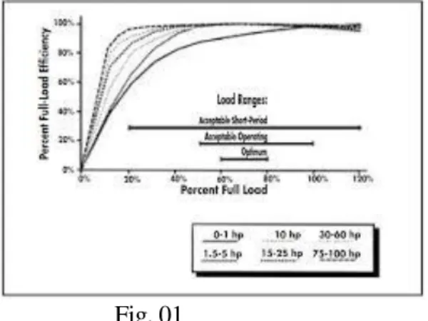
Most electric motors are designed to run at 50% to 100% of rated load. Maximum efficiency is usually near 75% of rated load. Thus, a 10-horsepower (hp) motor has an acceptable load range of 5 to 10 hp; peak efficiency is at 7.5 hp. A motor’s efficiency tends to decrease dramatically below about 50% load. However, the range of good efficiency varies with individual motors and tends to extend over a broader range for larger motors, as shown in Figure 1. A motor is considered underloaded when it is in the range where efficiency drops significantly with decreasing load
Fig. 01
Effect of overloading and under loading a Motor :
1. Efficiency get decreased 2. Power factor also get decreased 3. Heating of motor takes place 4. Insulation may get damaged 5. Losses increased
Precaution for loading a motor:
1. Never operate overloaded when voltage is below nominal or when cooling is impaired by altitude, high ambient temperature, or dirty motor surfaces.
2. Use proper starting method for motor 3. Maintain rated power supply to the motor
Energy conservation in Motor
1. Use energy efficient motors
2. Do not operate motor on under load 3. Do not operate motor on over load 4. Use P.F compensator
5. Replace over size motor with proper size motor 6. Use electric drive system
7. Do not use re winded motors 8. Use copper winding motors
Determining Motor Loads
Step 01 calculate Measured three-phase power in kW (Pi): Pi =( V x I x PF x √3)/ 1000 KW
Pi = Three-phase power in kW ,V = RMS voltage, mean line-to-line of 3 phases, I = RMS current, mean of 3 phases,
Step 02 calculate Input power at full-rated load in kW (Pir): Pir =( hp x 0.7457) /ηfl KW
Where: Pir = Input power at full-rated load in kW hp = Nameplate rated horsepower ηfl = Efficiency at full-rated load
Step 03 calculate load:
Load =( Pi /Pir) x 100% kw
Where: Load = Output power as a % of rated power Pi = Measured three-phase power in kW
Pir = Input power at full-rated load in kW
Need for Energy efficient Motors
These motors are very useful in energy conservation having following advantage 1. Low cost of operation due to less consumption of electricity.
2. Low noise/ silent operation which makes it suited for indoor use.
3. Less heating of motor due to the efficiency factor being high. Which means that you can run these motors for long periods at a time.
4. Low maintenance because of the higher quality materials used. The chances of breakdown are very slim.
5. Life of the these machines is generally higher than regular machines. 6. Good p.f
7. High efficieny 8. Low losses
9. Reduced size and weight 10.More reliable operation
Initial cost versus life cycle cost:
life cycle cost : Life cycle cost is the sum of all recurring and one time (non-recurring) costs over the full life time. It includes purchase price, installation cost, operating costs, maintenance and upgrade costs
Initial Cost : The initial cost of the Motor at which it is purchased . It includes only one time purchase price.
Cost Analysis on life cycle basis
To calculate an asset’s life cycle cost, estimate the following expenses: 1. Purchase
2. Installation 3. Operating 4. Maintenance
5. Financing (e.g., interest) 6. Depreciation
7. Disposal
Add up the expenses for each stage of the life cycle to find your total
Various constructional features of EEMs:
1. Energy efficient electric motors utilize improved motor design, improved design results in less heat dissipation and reduced noise output
2. Follow procedure for labeling standard
3. Energy-efficient motors are constructed with improved manufacturing techniques
4. Energy-efficient motors are constructed with superior materials 5. Energy-efficient motors are constructed with improved insulation 6. Energy-efficient motors are constructed with improved bearing lives
7. Energy-efficient motors are constructed with improved lower waste-heat output 8. Energy-efficient motors are constructed with improved less vibrations
9. Energy-efficient motors are constructed with flameproof enclosure 10. Energy-efficient motors are constructed with thinner laminations
11.Energy-efficient motors are constructed with Thicker conductors and more copper contents
12.Energy-efficient motors are constructed with Longer core length with reduced air gap
13.High-quality Aluminum used in the rotor frame
Comparison between EEM and Standard Motors
1. EEM have higher efficiency for same rating in comparison to standard motor 2. EEM produce low noise for same rating in comparison to standard motor 3. EEM have long life for same rating in comparison to standard motor
4. EEM require low maintenance for same rating in comparison to standard motor 5. EEM have low core and copper losses for same rating in comparison to standard
motor
6. EEM have low operating temperature for same rating in comparison to standard motor
7. EEM can operate more satisfactorily in comparison to standard motor 8. EEM more reliable in comparison to standard motor
9. EEM are having reduces size for same rating in comparison to standard motor
Unit No. 05
Energy efficiency in Electrical Utilities
Understanding Electricity BILL
Electricity Bill : The bill that Electricity distribution board issues to a elctricity consumer.It contain various information like account number , break up detail of bill charges , units consumed , tariff etc.
Tariff structure : Theelectricity tariff structure is the combination of per unit rates, additional charges, and other rules that determine how your electricity bill is
calculated.
Consumer categories are:
1. Residential 2. Commercial 3. Industrial 4. Agricultural
Different types of tariff structures : o Flat demand tariff
o Slab rate tariff
o Simple tariff
o Flat rate tariff
o Step rate tariff
o Block rate tariff
o Two part tariff
o Three part tariff
Apart from this more specific tariffs like:
Time off day tariff
Time of use tariff
Power factor tariff
Maximum demand tariff
Load factor tariff
Electric Power
Definition: The rate at which the work is being done in an electrical circuit is called an electric power.
Where V is the voltage in volts, I is the current in amperes, R is the resistance offered by the
powered devices, T is the time in seconds and the P is the power measured in watts.
Unit of power = Watt , KW , MW
DC Power
The DC power is defined as the product of the voltage and current.
AC Power
The AC power is mainly classified into three types. They are the apparent power, active power and real power.
Resistive/Reactive Load
The Power Triangle
These three types of power—true, reactive, and apparent—relate to one another in trigonometric form. We call this the power triangle: (Figure below)
Power Factor(cosφ) : The cosine of phase difference is called electrical power factor.
Value of power factor lies between – 1 to +1 : (-1 < cosφ < 1 ) or
It also can be defined as cosine of angle between voltage and current Or
It is also defined as the ratio of the real(true) power to the apparent power a circuit
Sanction Load :Sanctioned load means the load in KW/ KVA which the Licensee has agreed to supply to the consumer from time to time subject to the governing terms and conditions. Consumer can not draw more than sanctioned load.
Maximum Demand : Maximum demand is the highest level of electrical demand monitored in a particular period usually for a period of month.
Contract Demand: Contract load or contract demand is the maximum KW (power) you can reach up to. In general you will be asked to pay penalty if you cross this limit.
Monthly Minimum Charge:It is a part of tariff , in which minimum monthly bill is charged based upon the sanctioned load even when no power is consumed by consumer
ENERGY EFFICIENCY IN COMPRESSED AIR SYSTEM
Energy Efficiency of Compressed Air Systems.
Compressed Air (CA) systems have a significant impact on the energy consumption
and efficiency of manufacturing systems.For energy efficiency a control system is employed with compressed air system.This control system reacts to the flow and pressure of
the air output and determines which compressors need to be loaded and which ones to be unloaded.
Where is Compressed Air Used?
Compressed air powers many different kinds of devices. It can be used to push a piston, as in a jackhammer; it can turn a shaft, as in a dental drill; or it can be expanded through a nozzle to produce a high-speed jet, as in a paint sprayer.
Types of Compressors
1. Reciprocating compressors
2. Rotary compressors
Types of reciprocating compressors 1. Reciprocating single acting compressors 2. Reciprocating diaphragm compressors
3. Reciprocating rocking piston type compressors
Types of rotary air compressors 1. Rotary sliding vane compressors
2. Rotary helical screw compressors
Applications of air compressors:
1. Adding air to tires on bikes and on vehicles
2. Cleaning tight spaces on equipment or other items with air pressure 3. Painting with an airbrush for small
4. Using various pneumatic tools
5. Painting vehicles in an auto body shop
6. Sanding in an auto body shop or in woodworking 7. Providing dental and medical services
8. Using pneumatic drills and hammers on construction sites 9. Powering various air tools in an automotive repair shop 10. Using an air blowgun to clean machinery
11. Sandblasting in a machine shop and manufacturing facilities
Leakage Test of Air Compressor
The purpose of the leakage test is to establish the performance of the system from an energy efficiency perspective. It involves a walk around pipe work to assess for damage or
tampering.
Leak Detection
Since air leaks are almost impossible to see, other methods must be used to locate them. The best way to detect leaks is to use an ultrasonic acoustic detector, which can recognize the high frequency hissing sounds associated with air leaks.
A simpler method is to apply soapy water with a paint brush to suspect areas.
Energy saving opportunities in compressors
1. Reduction of demand:
The minimum quantity of compressed air should be used for the shortest possible time
2. Maintenance: Better maintenance will save energy
3. Monitoring : Maintenance can be supported by monitoring using proper instrumentation
4. Reduction of leaks (in pipes and equipment): Leaks cause an increase in compressor energy consumption and maintenance costs. So all possible leaks points should be monitored continuously.
5. Electronic condensate drain traps (ECDTs) : It offer improved reliability and are very efficient as virtually no air is wasted when the condensate is rejected
6. Reduction of the inlet air temperature : Reducing the inlet air temperature reduces energy used by the compressor
7. Optimizing the compressor to match its load : selection of over size or under size air compressor may be avoided.
8. Proper pipe sizing: Pipes must be sized correctly for optimal performance or resized to fit the compressor system
9. Installing adjustable speed drives (ASDs): When there are strong variations in load and/or ambient temperatures there will be large swings in compressor load and efficiency. In those cases installing an ASD may result in attractive payback periods.
Energy conservation in HVAC and refrigeration system
HVAC( Heating Ventilation Air Conditioning) :
HVAC is the technology of indoor and automatic environmental control.HVAC maintain a desired level of temperature , humidity and cleanness of air.Refrigeration: Refrigeration is defined as a process of producing and maintaining the temperature in a space below atmospheric temperature.
Energy efficiency ratio is the ratio of the cooling capacity of an air conditioner measured in British Thermal Units (BTU) per hour to the total electrical input measured in watts. Air conditioners having high EER are considered to be most cost effective.
Energy saving opportunities in HVAC:
Optimum Design (Heat Load and Air Flow Requirements) Monitoring & Control
Automation
Effective Preventive Maintenance Minimisation of Heat Energy Losses Minimisation of Leakage Losses Energy Efficient HVAC Components Waste Heat Recovery
Tune up the HVAC control system.
Balance the system to minimise flows and reduce blower or fan or pump power requirements.
Eliminate or reduce reheat whenever possible.Use appropriate HVAC thermostat setback. Use morning pre-cooling in summer and pre-heating in winter (i.e. – before electrical peak hours).
Improve control and utilisation of outside air.
Reduce HVAC system operating hours (e.g. – night, weekend). Optimize ventilation.
Ventilate only when necessary.
Provide dedicated outside air supply to kitchens, cleaning rooms, combustion equipment, etc to avoid excessive exhausting of conditioned air.
Use evaporative cooling in dry climates.
Reduce humidification or dehumidification during unoccupied periods.
Establish an HVAC efficiency maintenance program. Start with an energy audit and follow-up
Clean HVAC unit coils periodically and comb mashed fins.
Upgrade filter banks to reduce pressure drop and thus lower fan power requirements. Check HVAC filters on a schedule (at least monthly) and clean/change if appropriate. Isolate air-conditioned loading dock areas and cool storage areas using high-speed doors or clear PVC strip curtains.
Install ceiling fans to minimise thermal stray.
Relocate air diffusers to optimum heights in areas with high ceilings. Consider reducing ceiling heights.
Eliminate obstructions in front of radiators, baseboard heaters, etc.
Check reflectors on infrared heaters for cleanliness and proper beam direction. Use professionally-designed industrial ventilation hoods for dust and vapor control. Use spot cooling and heating Purchase only high-efficiency models for HVAC window units.
Put HVAC window units on timer control. Don’t oversize cooling units
Install multi-fueling capability and run with the cheapest fuel available at the time. Consider dedicated make-up air for exhaust hoods.
Minimise HVAC fan speeds.
Consider ground source heat pumps. Seal leak in HVAC ductwork. Seal all leaks around coils.
Repair loose or damaged flexible connections.
Eliminate simultaneous heating and cooling during seasonal transition periods.
Energy saving opportunities in Refrigeration:
Use water-cooled condensers rather than air-cooled condensers. Avoid oversizing – match the connected load.
Use gas-powered refrigeration equipment to minimize electrical demand charges. Use free cooling to allow chiller shutdown in cold weather.
Make adjustments to minimize hot gas bypass operation. Inspect moisture/liquid indicators.
Consider change of refrigerant type if it will improve efficiency. Check for correct refrigerant charge level.
Inspect the air and water leaks.
Establish a refrigeration efficiency maintenance program. Start with an energy audit and follow-up.
Thermal Basics:
Fuel:
Meaning of fuel is a substance which upon burning provides heat.
Types of fuels:
Solid Fuel : coal, charcoal, wood etc.
Liquid Fuel: ethanol and hydrogen
Fuel Gas : methane, carbon monoxide, propane, CNG
Bio fuel : Fuel derived from Bio Mass is known as Bio fuel
Thermal Energy : The Energy available in the form of heat is known as thermal energy.
Energy contents in fuels :Fuels are substances that react with oxygen in air and give off a
relatively large amount of heat. Reacting with oxygen in air, combustion, is a very commonly observed type of reaction that is very useful, due to the large quantities of heat energy
liberated. How much heat is generated depends on what type of fuel is burned and how much of the fuel is burned.
Heat Energy Units: As a form of energy, heat has the unit joule (J) in the International System of Units (SI). However, in many applied fields in engineering the British thermal unit (BTU) and the calorie are often used.