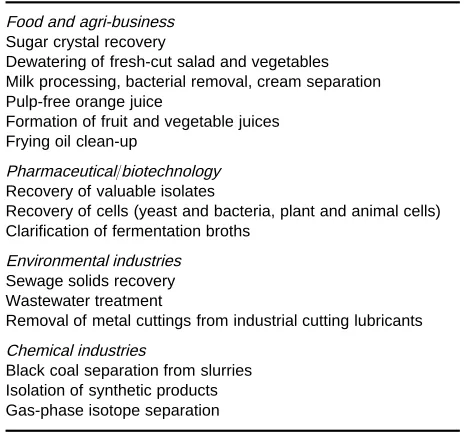
Table 1 Industrial use of centrifugal technologies Food and agri-business
Sugar crystal recovery
Dewatering of fresh-cut salad and vegetables Milk processing, bacterial removal, cream separation Pulp-free orange juice
Formation of fruit and vegetable juices Frying oil clean-up
Pharmaceutical/biotechnology Recovery of valuable isolates
Recovery of cells (yeast and bacteria, plant and animal cells) Clarification of fermentation broths
Environmental industries Sewage solids recovery Wastewater treatment
Removal of metal cuttings from industrial cutting lubricants Chemical industries
Black coal separation from slurries Isolation of synthetic products Gas-phase isotope separation
Large-Scale Centrifugation
T. Beveridge, Agriculture and Agri-Food Canada, Pacific Agri-Food Research Centre, Summerland, BC, Canada
Copyright^ 2000 Minister of Public Works and Government Services Canada
Introduction
Industrially, centrifuges are used for a variety of pur-poses related to separation of materials on the basis of density. This separation usually involves separation of insoluble particulates from supernatant liquids, but can also include extraction of dissolved substances from one immiscible liquid to another of different density, separating the mixed liquids centrifugally. The blending of the liquids, transfer of the solute and separation of the immiscible phases are sequentially carried out in the same machine at high speed.
Generally, centrifuges are used throughout many manufacturing industries (Table 1), to separate sus-pended solids from liquid utilizing the centrifugal acceleration of the suspended particles directed out-ward from the axis of rotation. This force initiates the particle movement to the centrifuge periphery where it is trapped or contained by the wall of the rotating body. Alternatively, a density difference between two immiscible liquids is exploited to accelerate sep-aration of the liquids (i.e. fat sepsep-aration in dairies for cream or butter manufacture). A specialized use in-volves separation of water from fresh-cut vegetables before modiRed atmosphere packaging.
Much experience and information related to indus-trial-scale centrifugation exists within companies manufacturing the centrifugal machinery and these sources should not be overlooked when seeking in-formation. Table 2 lists a representative selection of companies involved in the manufacture of centrifuges and their Internet addresses current at the time of writing. The Internet itself should not be overlooked as a source of information: simply typing the word ‘centrifuges’ in the request space of one search engine provided over 25 000 items for perusal.
Centrifugation is treated as a separation unit op-eration in chemical engineering and the article in Dahlstrom et al. (1997) by Leung on centrifuges should be consulted for an engineering perspective (see Further Reading). For a comprehensive treatment of industrial centrifugation technology, Leung’s book on industrial centrifugation technology should be consulted.
Over the past 10}15 years the growing uses for centrifuges industrially has resulted in a plethora of special centrifuges designed and adapted to particular uses. However, the machines may, in general, be characterized according to the classiRcation of
Table 3. Centrifuges fall into two general classiR ca-tions, termed sedimentation centrifuges andRlter cen-trifuges. In sedimentation centrifuges, solids are transported to the periphery wall of the rotating ma-chine bowl and collected against this surface; liquid is removed from the solids by the close packing of the individual particulates. InRlter centrifuges the solids are transported to the surface of aRlter element and the solids trapped on thisRlter, while the liquid drains through the particulates and exits through theRlter surface. The mechanism of solids drying is thus quite different between the two types of machine and the types of material each would be expected to treat most efRciently also differ consider-ably. The other important parameter is whether or not the machines are fed continuously or in batch mode. Generally, batch-mode machines are often considered obsolete for large scale separations, with the important exceptions of the continuing use of batch-mode basket centrifuges for the last recovery stages for white sugar and in the fresh-cut vegetable industry. Other exceptions also exist.
Table 2 Companies manufacturing centrifugal equipment which may be contacted through the Interneta
Alfa Laval Sharples http://www.als.thomasregister.com Barrett Centrifugals http://www.barrettinc.com
Bird Machine http://www.bakerhughes.com/bird/ birdhome.htm
Carr Separations http://www.carrsep.com Dorr-Oliver http://www.dorroliver.
thomasregister.com Eillert Veg. Proc. Mach.b http://www.eillert.nl
Rousselet Centrifugation http://www.rousselet.com Tema Systemsc http://www.tema1-usa.com/
corp.htm
Westfalia Separator http://www.westfalia.com/ default.htm
aThe list is representative, not exhaustive. bFresh cut vegetable
processing. cManufactures under licence from Siebtechnik
(Germany).
Table 3 Classification of centrifuges for industrial use accord-ing to general principles of operation
Sedimentation centrifuges Continuous feed
Solid bowl decanter (scroll-type centrifuge) Tricanter
Disk centrifuges (separators) Intermittent discharge Nozzle discharge Hydrocyclones Batch feed
Imperforate basket (generally considered obsolete, replaced by decanter)
Solid bowl Tubular Filter centrifuges Continuous feed
Pusher centrifuge (single- or double-stage) Screen/scroll
Screen bowl decanter Batch feed
Vertical basket (particularly for sugar industry and fresh-cut produce)
Peeler
along with an estimate of the range ofgforces avail-able from each machine type, is provided for pur-poses of illustration and estimation of requirements. Basket centrifuges are normally of low speed and provide maximumgforces in the 1500}2000 range.
Sedimentation Centrifuges
Centrifuges in this group (Table 3) collect particles against the centrifuge bowl wall. The centrifugal force exerted on a particle which causes particle movement to the wall is often expressed as the num-ber of earth gravities (g) which a machine is capable
of developing (Figure 1). Particles sediment in the centrifugal Reld at a rate which increases with the centrifugal speed, increased particle size, increased density difference between liquid and solid phases, increased centrifuge radius and decreased
Suid viscosity. The physical size, shape, design and construction of the centrifuge, in part, determine machine performance, but other factors affecting the properties of the feedstock are also important. Good separations of solid and liquid usually equate to high sedimentation velocity since large scale separ-ations are usually carried out in a production plant where time is important, or in continuous-Sow equipment where sedimentation velocity affects throughput rates.
Machine performance criteria are usually depen-dent on the purpose of centrifugation and can be measured by the purity of the separated liquid phase or the completeness of the removal of the solid phase. Performance may also be measured by several other criteria, some of which are listed inTable 4. A par-ticularly effective method of enhancing separ-ation performance is through increasing the diameter of the particles sedimented. This can be done by careful selection of conditions or addition of coagu-lants or Socculants. The purpose of coagulation or
Socculation is to destabilize particles, inducing them to come together and agglomerate to form larger aggregates. This can be accomplished by modifying the surface charge characteristics, by modifying the hydrophobic/hydrophilic character of the particles, or by using surfactants to reduce water-binding char-acteristics. Alternatively, charge repulsion by indi-vidual particles is reduced by adding polyvalent ca-tions such as aluminium or ferric ions. The materials and methods used to effect Socculation/ coagula-tion are listed inTable 5. A wide array of commer-cially available materials are marketed carrying a wide range of molecular sizes. TheSocculant/ co-agulant choice can be partially made on the basis of chemical knowledge of the particles to be sedimented, but theSocculant manufacturer’s recommendations should also be considered in combination with em-pirical screening tests. Flocculant manufacturers can be particularly useful sources of information and again the Internet should not be overlooked as a source.
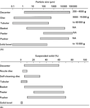
[image:2.568.49.279.474.710.2]Figure 1 (A) and (B) Approximate capabilities of various centrifuge forms to sediment/separate particles and levels of suspended solids applicable. NA, Not applicable or not relevant (generally less than 1500g). Adapted with permission from (http:// www.tema1-usa.com/centrifu.htm) and Brunner and Hemfort (1988).
Table 4 Selected performance criteria for centrifuges accord-ing to functional definitions
Cake dryness or cake moisture content Total solids recovery
Polymer dosage (flocculent concentration) Yield
Volumetric or solids throughput
Purity of isolate of interest (either fluid stream or solids discharged)
Power consumption Maintenance requirement
possible limits the acceptable Socculants. Down-stream processing of fermentation broths or biotech-nologically derived natural products for removal of particulate from a liquid stream provides another application of theseSocculant materials. When used prior to unit operations such as chromatography or adsorption, these materials can help provide a clean, particle-free feed which will not block the columns
[image:3.568.51.276.611.710.2]Table 5 Coagulants and flocculants. Adjustment of conditions or addition of specific chemicals achieves required increase in particle size
Metal salts, especially of aluminium or ferric iron (Al2(SO4)z16H2O; Fe2(SO4)3z9H2O)
Natural flocculants Starch
Gums Tannin Alginic acid
Sugar/sugar acid polymers Polyglucosamine (chitosan) Synthetic flocculants
Polyacrylamides Polyamines/imines
Cellulose derivatives (e.g. carboxymethyl cellulose) Polydiallydimethyl ammonium chloride
Chilling temperatures below 203C, particularly yeast cells pH adjustment in range 3}6
Concentration}increases particle concentration, increasing collision frequency
Adapted from Whittington (1990) with permission.
Figure 2 Schematic diagram of a decanter (scroll-bowl) centrifuge showing the major parts and indicating mode of operation. Reproduced with permission from Westfalia Separator AG, Oelde, Germany.
Decanter Centrifuges
A schematic diagram of a solid bowl decanter is shown in Figure 2. The machine consists of a hori-zontally oriented cylindrical bowl with one end tapered to form a cone. Within this cylindrical/ coni-cal section is a conveying scroll, with the same proRle as the cylindrical/conical bowl. This scroll is rotated at a slightly different speed from the bowl through a gear system or via a separate drive. This arrangement Rxes the differential speed, allows adjustment during operation, or accommodates auto-matic systems. Either method ensures that the scroll turns fast enough to avoid blockage by the solids which accumulate on the scroll faces, while allowing maximum solids retention times for good separations and dry ejecta. An automatic system allows the scroll speed to be adjusted to optimize the differential
speeds under operating conditions. The length of the cylindrical and conical sections and the conical angle may be varied, as can the scroll design, to accommod-ate diverse requirements of feedstock to achieve solids separations. Slurry to be separated is fed continuously through the centre pipe to be distributed evenly near the level of the conical taper and is accelerated to bowl speed. During acceleration, high shear forces are generated and this may result in considerable foam generation in some slurries such as food mater-ials which contain protein or pectin capable of retain-ing air in suspension.
The depth of the liquid pool rotating against the bowl wall is determined by the positioning of theSuid discharge ports, dams or pick-up tubes. Solids settle through this pool to the bowl wall and are conveyed to the outlet ports at the distal conical end where they are ejected. The solids undergo a drying effect as they are dragged along the bowl wall and elevated to the exit ports as liquid drains back to the pool. Given the decanter conRguration, there are four parameters which can be varied: scroll/bowl differential speed, pool depth, bowl rotational speed and feed rate. Fluid or supernatant is conveyed countercurrent to the solids, following the path of the scrollSights, to exit at a discharge port at the end of the cylindrical section. Centrifugal force can vary to over 4000g
depending on application and centrifuge.
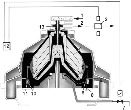
[image:4.568.128.445.547.686.2]Figure 3 Bowl section of a self-cleaning disc stack centrifuge indicating direction of fluid flow and ejection of sedimented solids through passages controlled with hydraulically operated pistons. Discharge is intermittent. Nozzle machines allow for continuous discharge of solids through throttled nozzles while solid bowl machines without solid discharge mechanisms require manual cleaning from time to time depending upon feedstock solids. 1, Feed; 2, discharge; 3, photocell; 4, discs; 5, sediment holding space; 6, solids ejection ports; 7, operating water valve; 8, drain hole; 9, opening chamber, 10, closing chamber; 11, annular piston; 12, timing unit; 13, discharge pump. Reproduced with permission from Westfalia Separator AG, Oelde, Germany.
of two immiscible liquid phases is possible but is normally done in a disc-stack centrifuge specially designed for this purpose (i.e. cream separator). In the solid}liquid mode of operation, the ability to handle high solids content feed streams continuously, ef-fectively and efRciently has made dewatering of municipal and industrial sewage a major use for de-canter centrifuges. For similar reasons these machines have been used extensively for dewatering Rne coal and for separation of mineral slurries in the mining and mineral-processing industries.
Decanters capable of separating three phases have been used to reRne vegetable oils from complex feed-stocks such as coconut, producing fat, milk and grated coconut solid fractions, recovery or animal fat from rendering operations and recovery of waste oil in petroleum reRning. Watery oil derived from tank bottoms or trapped in containment lagoons which contain suspended solids may have this oil recovered using these machines. In each case value is added through the recovery of the oil phase as a saleable product. More recently, two-phase decanters have been adapted to replace presses in the extraction and further processing of a wide variety of fruit and veg-etable juices. Separation in a tricanter of commercial-ly exotic fruits such as sea buckthorn into pulp oil, juice and seed-enriched solid ejecta provides a poten-tial future use of centrifugal technology. New, innovative uses for this versatile machine are still emerging.
The disadvantage of the machine is its inability to clarify liquid streams completely, as some suspended solids remain in the emerging stream. If complete clarity is required, another clarifying method must be used following decanter centrifugation. This may in-clude equipment such as a disc centrifuge (clariRer) or
Rlter system. For example, processes described for the extraction of fruit juices with a decanter replacing the press often have a clarifying disc stack centrifuge in the line following the decanter to provide the Rnal solids removal and provide the brilliant clarity de-sired in many juice products. Alternatively, the clarifying centrifuge can be operated in such a way as to remove the particles larger than 0.5m diameter to provide a stable juice opalescence.
Disc Stack Centrifuges
Originally designed as cream separators, these ma-chines have achieved a high degree of sophistication and today represent a versatile group of centrifuges capable of achieving very highgfactors, commonly ranging from 3000 to 15 000. The original applica-tion of cream separaapplica-tion is still performed as a specialized function in dairies where these machines
are also used for milk clariRcation and bacterial re-moval prior to high temperature}short time pasteur-ization. The disc stack centrifuge is a vertical-axis machine consisting of a series of conical spacers stacked within the centrifuge rotor (Figure 3). The centrifuge is arranged to allow continuous Sow of feedstock into the lower part of the bowl. FluidSows up through the channels formed by the stacked coni-cal elements and particulates are sedimented to con-tact the inclined surface of a conical element. The particulates on the conical element are forced down-ward and outdown-ward until they underSow the cone to collect on the bowl wall. The effect of the angled conical element is to shorten the distance required for particle migration to a surface and reduce the turbu-lence produced by materialSows within the centri-fuge, resulting in rapid and complete clariRcation of the Suid stream. The number and spacing of the conical elements are important factors in the separ-ation process.
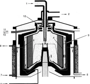
Figure 4 Solid-bowl separator for separating and collecting fine suspended solids in a liquid stream. 1, Product feed; 2, product discharge; 3, bowl insert; 4, removable liner; 5, coolant discharge (bowl); 6, coolant feed (bowl); 7, coolant feed and 8, coolant discharge (upper section of frame); 9, removable liner; 10, coolant discharge and 11, coolant feed (hood); 12, centripetal pump. Reproduced with permission from Westfalia Separator AG, Oelde, Germany.
use of water-immiscible organic solvents and rapid separation of the two phases can be achieved in these machines. Removal/isolation of culture-grown bac-terial or other cell is a useful function in the biochemi-cal industries. In any role, consideration should be given to the need to seal the centrifuge against the dispersion of aerosols which may contain dangerous biochemicals, nonaqueous vapours or bacterial cells which may be toxic,Sammable or explosive. Flushing with an inert gas such as nitrogen or carbon dioxide to avoid oxidation, and the need for temperature control of the centrifuge, feedstock and products should also be considered.
Disc stack centrifuges come in three basic conR g-urations. In one conRguration the sedimented solids are continuously ejected through carefully sized nozzles at the bowl periphery (nozzle discharge), allowing continuous operation of the machine with continuous discharge of solids. However, the degree of compaction of the solids is limited by the need to be free-Sowing, and solids exit as a concentrate (&50%). In the second conRguration, the bowl is equipped with the means to open a port at the periph-ery of the rotating bowl. This opening may be closed with a slide or piston which is hydraulically opened
according to a pre-set programme. The programme may be set by time or the centrifuge may be equipped with a monitoring device on theSuid exit side which monitors the light-scattering capability of the clariR -ed output. Above set limits clarity deterioration trig-gers solid discharge. The centrifuge illustrated in Fig-ure 3 is of this self-cleaning type. The third conR gura-tion is a solid-wall bowl which is primarily used for separation of liquid mixtures containing little or no solids. The bowl is cleaned manually, or with auto-matic removal machinery which requires process in-terruption, so it is advantageous for the sedimented solids content to be low since the machine operates in batch mode and machine capacity will be a function of the clean-out rate.
Solid Bowl and Tubular Centrifuges
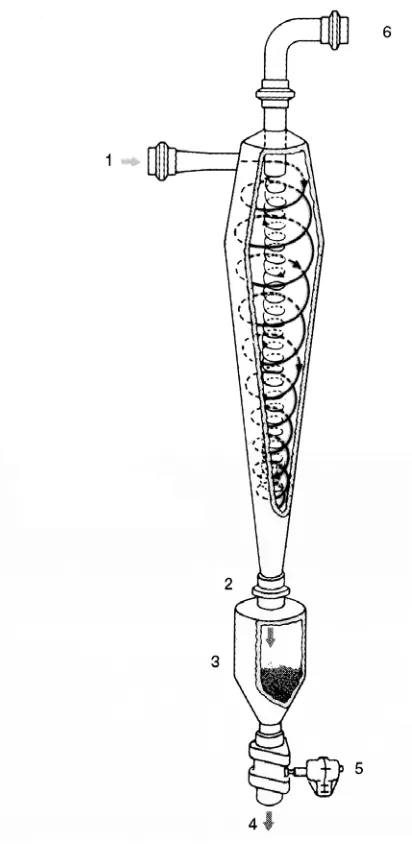
Figure 5 Schematic diagram of a hydrocyclone. 1, Feed; 2, apex nozzle; 3, grit pot; 4, outlet, solids; 5, valve; 6, discharge, clarified liquid. Reproduced with permission from Westfalia Sep-arator AG, Oelde, Germany.
and generating very highgforces to above 40 000g, whereas the solid-bowl/chamber-bowl machines carry a larger diameter bowl and operate in the 5000}10 000g range. The solid-bowl machines are often equipped with a removable liner to facilitate solid removal and centrifuge cleaning, to reduce down time between batches. The narrow tube means that the solid-retaining capacity of the tubular centrifuge is small but the high g force makes the machine useful for collecting small particulate or cell debris in biotechnological applications. They are particularly useful for collecting a valuable partic-ulate present at low concentration which requires high relative centrifugal forces for its isolation. Final cleaning of a Suid stream is another application, particularly for the solid-bowl machine, if the solid to be removed is of a refractory type, which would impose extensive wear on the nozzles or solid ejection ports of a disc stack machine or where high compac-tation of the solids is of value. This latter condition can be very desirable for biotechnological applica-tions where isolation of expensive precipitates is a key function.
Hydrocyclones
This device is particularly unique as it separates solids and liquids by centrifugal principles, but contains no moving parts. The principle of the machine is illus-trated inFigure 5. The slurry orSuid to be separated is pumped at high speed and enters the conically shaped machine tangentially. The conical shape causes theSowing liquid to swirl or rotate within the cone, with the result that suspended solids move to the wall while clariRed liquid remains in the centre of the cone. This clariRed liquid is drawn off at the top of the cone while the separated solids move to the bottom of the chamber for removal. The degree of separation is generally coarse; however, hydrocyc-lonesRnd use in applications such as removal of sand or grit from fruit mash streams intended for juice extraction, to protect expensive equipment such as decanter scrolls or disc stack deslugging mechanisms from premature wear. TheyRnd use in pulp mills for paperRbre removal from liquid streams. These units are used extensively to remove particles from gas streams such asSue gases and as a particle collection mechanism for spray driers used in the production of food powders of various kinds. While the medium of drying and particle conveyance is air, and the preRx ‘hydro’ does not strictly apply, the principle is the same. Hydrocyclones may precede in line withR lter-ing centrifuges since they can be used to concentrate the centrifuge feed and increase the efRciency of the basket orRlter centrifuge.
Filter Centrifuges
These machines are characterized by sedimenting particulate on to a screen which may consist of slots, holes, a porous membrane, orRlter cloth, where the solids are retained while the liquid portion Sows through the screen to be carried away (Figure 6). Generally, the solids should be free-draining and at least 100}200m in diameter. These properties allow
Figure 6 Vertical basket centrifuge with pneumatic top discharge. Reproduced with permission from Krauss Mofferi, Munich, Germany.
settling tanks as pretreatment concentrators. The re-volving bowl may be driven either from above or below the rotating parts. The cycle of a variable-speed basket centrifuge consists of acceleration to medium speed, slurry feed and even distribution over the retainingRlter surface, and acceleration to opera-tional speed to remove the liquid portion. At this higher speed the dewatered cake may be washed if the centrifuge is equipped with interior washing nozzles, and dewatered for theRnal time. The rotor speed is decreased and the solids removed, usually by mechan-ical means using a knife or plow to release the cake from the centrifuge wall. Solids are either dropped through the centrifuge bottom in a vertical axis ma-chine, or gravity-fed down a chute in a horizontally mounted machine. Batch machines offer S exibil-ity in centrifugal conditions, allowing adjustments for feed rates or feed solid concentration; however, they are not widely used except in the white sugar industry
since the higher throughput capacity makes continu-ous centrifuges more attractive.
Basket centrifuges can be made continuous by in-corporating the means of removal of solids while the machine operates. Machines mounted horizontally utilizing a knife to peel the solids from within the centrifuge bowl are termed Peeler-type basket centri-fuges (Table 3). In this conRguration the knife enters the centrifuge and unloads the cake while the ma-chine operates at full speed. This overcomes the re-quirement for speed management and permits shorter cycles and higher throughput capacities than simpler batch basket centrifuges. Vertical pneumatic convey-ing (Figure 6) is another possibility. Pusher centri-fuges also fulRl this requirement for continuous operation. A double-stage pusher centrifuge is shown inFigure 7. Multiple-stage machines are available.
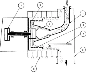
Figure 7 A two-stage pusher-type centrifuge. Feed enters at (1) and is accelerated while passing over the cone (2) and distributed on the first-stage basket (3). The first-stage basket (4) hydraulically reciprocates under a static pusher plate (5), which advances the filter cake to the second-stage basket on the back stroke. The forward stroke of the first basket pushes the second basket cake off into the collecting chute (6). The means to wash the filter cake (7) and collect mother liquor or wash fluids (8) is usually provided. Reproduced with permission from White (1979).
hollow tube to a solid distribution device which dis-tributes the slurry evenly on the basket during the back stroke of the hydraulically driven distributing plate. On the forward stroke the distributing plate exerts a pressure on the deposited cake, causing it to overSow the open end of the basket. If required, the deposited cake may be washed before the return stroke causes overSow of the solids. The screen/scroll centrifuge is also horizontally oriented, but the basket is conical-shaped and transport of the deposited, cen-trifugally dried slurry is accomplished by a scroll or scrapper blades in a manner reminiscent of the de-canter scroll. The transported solids overSow the open end of the basket and are removed from the machine. The screen-bowl decanter is of similar de-sign to the solid-bowl decanter discussed earlier ex-cept for the addition of a cylindrical screen behind the conical section of the bowl. The scroll spans the entire length of the bowl including the screen and conforms to the proRle of the bowl and screen. Solids retained on the screen are scraped by the scroll to an exit beyond the screen. The purpose of the machine is to combine the solid sedimenting centrifuge with a screen centrifuge in an attempt to obtain a drier cake. Washing of retained solids may be effected in the Rrst portion of the screen, while dewatering taking place in the second part. Decanters such as this
may provide serious competition to the peeler and pusher centrifuges by facilitating continuous separ-ations in a more compact, mechanically simpler package.
A special application which is of growing import-ance in the food industry is the use of low speed basket centrifuges to dewater or dry fresh-cut veg-etables, especially salad greens, for later use in
modi-Red atmosphere packages (Figure 8). These machines are usually of lighter construction than the heavy-duty machines described above, are batch-operated, and often have reusable rotating perforated baskets, to facilitate rapid unloading and reloading of the centrifuge. The reusable baskets are usually of light construction, often plastic, to allow easy manual handling and economic replacement. Such materials have low tolerance for acceleration and deceleration forces but are well suited for undemanding applications.
Summary
Figure 8 Small industrial-scale centrifuge for dewatering fresh-cut produce. The machine is operated in batch mode, but use of insertable plastic bowl minimizes down time between loads. Reproduced with permission from Freshline Machines, Sydney, Australia.
separations such as dewatering of vegetables. Perfor-mance demands also vary widely, ranging from high
gapplications required in isolating and manufactur-ing the diverse products of biotechnology to dewater-ing hundreds of tons of municipal sewage per day using machines of relatively lowgcapability. This is made possible by the wide variety of machines avail-able. The recent application of decanters as press replacements in the fruit and vegetable juice industry required the independent development and wide-spread use of pectin-digesting enzymes (pectinases) for routine juice production. The reduction in viscosity
and release of dense core particles from the fruit mash which is characteristic of the action of these enzymes is a necessary precondition for the successful use of decanters. The fruit-processing industry is in-creasingly interested in the production of products from new, unconventional fruits and vegetables. An example is sea buckthorn, a fruit which consists of a seed, pulp and pulp oil, a three-phase system which might be separated into an oil stream, a stable opal-escent juice and a seed containing pulpy ejecta in a single operation using a three-phase decanter. From these two examples drawn from the author’s experi-ences in this industry it appears that future innova-tions are likely to be applicainnova-tions, which will in turn drive further reRnement and development of the cen-trifugal machinery.
See also: II/Centrifugation: Theory of Centrifugation.
Further Reading
Beveridge T (1997) Juice extraction from apples and other fruits and vegetables.Critical Review of Food Science and Nutrition37: 449}469.
Brunner KH and Hemfort H (1988) Centrifugal separation in biotechnological processes. In: Mizrahi A (ed.)
Downstream Processes: Equipment and Techniques.
Advances in Biotechnological Processes, vol 8, pp. 1}50. New York: Alan R. Liss.
Dahlstrom DA, Bennett RC, Emmett RC et al. (1997)
Liquid}solid operations and equipment: centrifuges. In:
Perry RH, Green DW and Maloney JO (eds) Perry’s
Chemical Engineers’ Handbook, 7th edn, pp. 18}106. New York, NY: McGraw-Hill.
Leung WW-F (1998)Industrial Centrifugation Technology. New York: McGraw-Hill.
White WF (1979) Centrifuges. In: Bhatia MV and
Cheremisinoff PN (eds) Solids Separation and
Mix-ing. Process Equipment Series, vol. 1, p. 81. Westport CT: Technomic.
Whittington PN (1990) Fermentation broth clariRcation
techniques. Applied Biochemistry and Biotechnology
23: 91}121.
Macromolecular Interactions: Characterization by
Analytical Ultracentrifugation
D. J. Winzor, Department of Biochemistry, University of Queensland, Brisbane, Australia
Copyright^ 2000 Academic Press
Analytical ultracentrifugation refers to the analysis of a macromolecular solution by its subjection to