warwick.ac.uk/lib-publications
A Thesis Submitted for the Degree of PhD at the University of Warwick
Permanent WRAP URL:
http://wrap.warwick.ac.uk/108849
Copyright and reuse:
This thesis is made available online and is protected by original copyright.
Please scroll down to view the document itself.
Please refer to the repository record for this item for information to help you to cite it.
Our policy information is available from the repository home page.
A U
nified
P
rogramming
S
ystem
for
A
M
ulti
-P
aradigm
P
arallel
A
rchitecture
Ph.D. Thesis
August 1991
Computer Science Department
University of Warwick
John Vaudin
THE BRITISH LIBRARY
D O C U M E N T SU P PLY C E N T R EBRITISH THESES
N O T I C E
The quality of this reproduction is heavily dependent upon the quality of the original thesis submitted for microfilming. Every effort has been made to ensure the highest quality o f reproduction possible.
If pages are missing, contact the university which granted the degree.
Some pages may have indistinct print, especially if the original pages were poorly produced o r if the university sent us an inferior copy.
Previously copyrighted materials (journal articles, published texts, etc.) 'a r e not filmed.
Reproduction of this thesis, other than as permitted under the United Kingdom Copyright Designs and Patents A ct 1988, o r under specific agreement with the copyright holder, is prohibited.
T H IS T H E S IS H A S B E E N M IC R O F I L M E D E X A C T L Y A S R E C E IV E D
T H E B R IT IS H L IB R A R Y
D O C U M E N T S U P P L Y C E N T R E Boston Spa, W etherby W e st Yorkshire, LS23 7 B Q
A
bstract
Real time image understanding and image generation require very large amounts of computing power. A possible way to meet these requirements is to make use of the power available from parallel com puting systems. However parallel machines exhibit performance which is highly dependent on the algorithms being executed. Both im age understanding and image generation involve the use of a wide variety of algorithms. A parallel machine suited to some of these algorithms m ay b e unsuited to others.
This thesis describes a novel heterogeneous parallel architecture optimised for image based applications. It achieves its performance by combining two different forms of parallel architecture, namely fine grain SIM D and course grain MIMD, into a single architecture. In this w ay it is possible to match the m ost appropriate computing resource to e a ch algorithm in a given application.
As important as the architecture itself is a m ethod for programming it. This thesis describes a novel multi-paradigm program m ing language based on C++, which allows programs which make u se of both control and data parallelism to be expressed in a single coherent framework, based on object oriented programming.
D
eclaration
The composition of this thesis is entirely my own work. The work on which it is based was carried out within the VLSI A rchitecture Group in the Computer Science Department at Warwick University.
All work relating to the design and construction o f the Warwick Pyramid Machine was carried out jointly by the VLSI Group. I have been a member of the VLSI Group since it was first set up, and h av e been fully involved in every part of the design and some parts o f the implementation of the Warwick Pyramid Machine.
This joint work has been published in:
[Atherton 90a] [Atherton 90b] [Francis 90] [Nudd 88] [Nudd 89] [Nudd 90a] [Nudd 90b] [Nudd 91a] [Nudd 91b] [Vaudin 89a] [Vaudin 89b].
The work relating to the design and implementation of Pyramid C++ was carried out entirely by myself.
The work relating to the model based alignment estimation system, and its mapping onto the W.P.M. is my own work. This w ork was carried out as part of a larger project in which a number of people w ere involved. The work described here constituted the module of this project, for which I was responsible.
A
cknowledgements
C
ontents
1 1ntroduction...
1
1.1 Background___________________________________________ ___ _______ 1 1.1.1 Image Understanding_____________ _________________________ .2 1.1.2 Image Generation...- ... ... ... 3
1.2 Architectural S o lu tio n ... ... ... ...A 1.3 Thesis O utline... 3
2 P a r a lle l A r c h it e c t u r e s __________________________________________ .7 2.1 Introduction... 7
2.2 Parallel Architecture Classifications...9
2.2.1 Memory Structure... 12
2.2.1.1 Ideal Shared Memory Machine...12
2.2.1.2 Shared Memory... 13
2.2.1.3 Distributed Shared Memory...15
2.2.1.4 Distributed Memory—... 17
2.2.2 Interconnection Schemes... 19
2.2.2.1 Bus Based Systems...20
2.2.2.2 Connection Networks...21
Directly Connected Netxoorks_________________________ ....___3 2 Switching Networks... .24
2.2.3 Control Structure__________ ____________ ... ...26
2.2.3.1 SIMD Machines...26
2.2.3 2 MIMD Machines_______________________________________27 2.2.33 Granularity--- --- 2 8 2.2.3.4 Communication... JO 2.2.3 5 Local Autonomy...31
2.3 Existing Parallel Architectures... 3 2 2.3.1 MIMD Systems... ...3 3 23.1.1 Shared Memory Systems... 3 3 2.3.1.2 Distributed Shared Memory Systems... 34
23.1.3 Distributed Memory Systems...36
2.3.2 SIMD Machines... 38
2.4 An Architecture Optimised for Image Based A pplications...40
2.4.1 Architectural Features...41
2.4.1.1 Memory Organisation... 41
2.4.1.2 Communication Network--- --- ---.41
2.4.13 Control Structure...42
2.4.2 Existing Multi-Paradigm Architectures... 43
2.4.2.1 IUA (Image Understanding Architecture)... 43
2.4.2.2 The Disputer... ...45
2.4.23 Pixel Planes 5...45
3 T h e W a rw ic k P y ra m id M a c h i n e ... ...48
3.1 Introduction... 48
3.2 Design...49
3.2.1 Ousters... ... ...5 0 3.2.1.1 Symbolic Processor--- --- 5 0 3.2.1.2 O uster Controller...—...51
3.2.1.3 Iconic Layer... ... 51
3.2.1.4 Ouster Interconnection... 5 2 3.2.2 Multiple-SIMD Operation...5 3 3 5 Implementation...54
3.3.1 Host Machine ... 5 5 3.3.2 Symbolic Processor ... 5 5 3.3.3 Ouster Controller... ...5 8 3.33.1 Sequencer... ... 51
3.33.2 Scalar ALU... ... .62
3 .3.33 Central Bus... ...63
3.3.4 Iconic Array ...____ ______ ______ _....___ ____... ... M 33.4.1 Processing Element... 66
3.3.5 Cluster Controller Programming Model...69
3.4 Conclusions... 72
4 P r o g r a m m in g P a ra lle l A rc h ite c tu r e s ... 74
4.1 Introduction... ... 74
4.2 Implicit Parallelism... 75
4.2.1 Parallelising Sequential Programs... 75
4.2.2 Parallelising Functional Programs...79
4 3 Explicit Parallel Languages...83
4.3.1 Control Parallel Languages... ... 84
43.1.1 Shared Memory Constructs...5 5 Process frnti'(m._„.™„„_-„...m™...«„.„....„..„..»„...„„„..M....„86
Synchronisation... .86
4 3 .1 .2 Distributed Memory Constructs... 5 7 Communication and Synchronisation...87
4.3.13 Shared vs Distributed Memory... .90
4.3.2 Data Parallel Languages... .91
43.2.1 Fixed Topology Constructs... 91
43.2.2 Variable Topology Languages... .94
4.4 Conclusions... .96
5 A D u a l P a r a d i g m P r o g r a m m in g M o d e l ...98
5.1 Introduction... 99
5 2 Object Oriented Programming... 100
5.2.1 Structured Programming... — _____ 100 5.2.2 Abstract Data Types...101
5.2.3 Reusable Software Construction...102
5.23.1 Message Passing... 103
5 .23.2 Classes...104
5.3 Control Parallel Object Oriented Programming ...107
5.3.1 Actor*... 106
5.3.1.1 Controlling Message Acceptance...110
5.3.2 Introducing Multiple Thread*...„...„... 112
5.3.3 Discussion... 115
5.4 Data Parallel Object Oriented Programming... 116
5.4.1 Internally Parallel Objects... 116
5.4.1.1 Use of Existing Object Oriented Languages...118
5.5 A Unified Control and Data Parallel Programming Model...«119
5.5.1 Autonomous Parallel Objects...__...120
5.6 Conclusions... 121
6 P y r a m id C + + ...123
Introduction...123
Sequential C++--- --- ---- ---—--- ««««««124
Language Description...126
6.3.1 Support for Control Parallelism...127
63.1.1 Actors._________________________ 127 Actor C reation.... ... 128
Message Patting...130
Returning Results...131
Passing Parameters in M essages____ ««««««.____________ .._...133
Controlling M essage Acceptance...134
6.3.1.2 Coding Example... ...135
6.3.2 Support for Data Parallel Programming... 138
6.3.2.1 Parallel Images ...1 3 8 6.3.2.2 Conditional Expressions... 141
6.3.3 Support for Multi-SIMD Programming... 141
6.3.4 Discussion... 143
6.4 Implementation...143
6.4.1 Preprocessor...««..«..«««...«..«„143
6 4 1 2 Stub Classes „««««««««... ...144
6.4 2 Parallel Class Library... ...151
6.4.2.1 Array Memory Management ... 152
6.4.2.2 Image Operations...154
6.4.4.3 Cluster Assembler: CLASS... 157
6.4.3 Run Time System... 157
6.43.1 Router... 158
Deadlock Free Routing... .—--- ---...158
Parasitic Dependencies... 161
Ports______________________________________________________162 6.5 Conclusion*...163
6.5.1 Pyramid C++ in Context... 164
Control Parallel Support... 164
Data Parallel Support... 166
6.5.1 Portability Issues... ...;... 167
7 A p p lic a tio n s S tu d y _____________________________________________ 169
7.1 Introduction...169
7.2 Image Analysis: Object Alignment...169
7.2.1 Shape Based Techniques... 170
7.2.1.1 Limitations of Shape Based Techniques...171
7.2.2 Model Based Techniques... 172
7.2.2.1 Model Representation__________________________________ 173 7 2.2.2 Model Matching... 174
7.2.3 Implementation... 175
7.2.3.1 Choice of Characteristic Features...176
7.2.3.2 Image Processing and Feature Extraction...„... 178
Filtering and Edge Detection_________________ 178 Detection and Segm entation...—... ... ... ...178
Feature Extraction...179
7.2.3.4 Model Representation... 183
7.2.3.5 Feature Matching... 184
7.2.4 Results...--- 186
7.2.4.1 Timings...191
7 3 Image Generation: Polygon Rendering ... ..._____ 192 7.3.1 The Viewing Pipeline... 193
7.3.1.1 Transformation... 193
7.3.1.2 Clipping and Projection...195
7.3.1.3 Shading and Scan Conversion... 196
7.3.1.4 Hidden Surface Elimination...._______ ____ ...____ 196 7.3.2 Implementation... 199
7.3.2.1 Processor Farm ...„...199
Pyramid C++ Im plem entation...— ... ...201
7 3 .2 .2 Scan Conversion...303
Fuch's A lgorithm ....— ---— ... 2 0 4 Pre-Stored Patches...205
7.3.2.3 Hidden Surface Elimination .. ?Q5 7.3.3 Results...206
7.4 Cbndusiane...208
6 C o n c lu s io n s ...¿10
8.1 D iscussion....210
8.1.1 Hardware... ... ... ... ...___ ....210
8.1.2 System Software... .212
8.1.3 Application Software... ... ...— ... ...213
8.2 Contribution of this Wock... .213
8.3 Implications for Future Work... 2 1 4 B i b l io g r a p h y ...208
A p p e n d ix A _________________________________________________________.226 A.1 Introduction... 226
A.2 Language Extensions...226
A2.1 A ctors...227
A 2.2.1 Message Sender...— --- 77*
A2.2.2 Message Receiver...229
A_3 Parallel Class Library... ... .230
A3.1 Class Image... 231
A3.1.1 Public Definition...231
A.3.1.2 Member Functions...__ ... .232
A3.2 Class Patch...233
A3.2.1 Public Definition...733
A.3.2.2 Member Punctions....733
A.33 Class Cluster... .235
A3.2.1 Public Definition... ..236
Chapter One: Introduction
Chapter 1
Introduction
1.1 Backgrou nd
W hile conventional com puter architectures have ach ie v ed great improvements in performance up to now, there are still a number o f areas where these sequential computers cannot provide sufficient processing power to meet the requirements of the application. Notable am ongst these are real time image analysis and image generation, which have applications in robotics, defence, industrial inspection, design and simulation to name but a few.
W hile there are systems in use that can attempt some of these tasks, they are generally rather limited, often using specialised hardware which can only perform a restricted set of operations, which cannot be altered to meet changing requirements [Abram 85][Glassner 85].
Over the past six years the VLSI Group at the University of W arw ick's Computer Science Department have been working on the design o f a more general system based on a fully programmable m assively parallel architecture which is sufficiently powerful to perform a wide variety of image based tasks in real time, and which is not restricted to a sm all set of algorithms.
The key to this design has been the development of an architecture which, while retaining complete programmability, is optimised to the class of algorithms that are typically found in image based applications. This
optimisation has been based on a study of the structure of im age based applications, in particular image understanding and image generation.
1.1.1 Im a g e Understanding
An image understanding system takes an image as input, perform s some processing on that image, and produces some form of high-level description of the contents of the image as output. To do this it would typically proceed in a number of stages, at each one refining the data into a more abstract form.
Initially low-level or iconic processing is performed, which includes such operations as edge detection and filtering. This produces a modified im age as output, which forms the input to the next stage of processing, w hich is typically segmentation.
Segmentation involves subdividing the image into regions of interest which are associated with objects or parts of objects in the image. The exact method used will depend on the types of regions which are to be extracted. Typical systems use regions with uniform grey levels or textures, lines o r other geometric shapes or comers.
Once the image has been segmented into regions of interest, inform ation about each o f the regions is extracted. Typically this information might include grey level, variance, length and end points of a line, or the angle of a corner. This process, known as feature extraction, performs an abstraction from the iconic image data to a more numeric representation which is passed on to the final stage of processing.
Chapter One: Introduction position and orientation of the objects in the image.
Once a hypothesised model has been generated, the system can then perform purely symbolic high level reasoning based on the interrelationship of these hypothesised objects. This reasoning will typically form part o f the wider system in which the image analysis system is being used, such a s a robotic control system, and will allow the overall system to make decisions based on the visual input to the system.
1.1.2 Im a g e Generation
Image generation is essentially the reverse process of image analysis. Instead of starting w ith an image and producing a model of the contents of the image, the system starts with a model and produces an image o f that model. As with im age analysis systems, image generation systems proceed in a number of stages.
The first step in processing typically consists of viewing transformations, where the model is transformed into the coordinate system of th e viewer. This may involve different transformations for different objects in the scene, if the relationship between the various objects is not fixed. W orking out these relationships may be a complex problem in itself if, for exam ple, the different objects were aircraft in a flight simulator.
In the next stage the illumination of the objects is calculated based on their positions with respect to a set of light sources. Most systems w ill perform some clipping at this stage, where objects out of view are rem oved from further calculations.
Next the objects are decomposed into their constituent parts, usually planar polygonal patches, which are then projected onto the two dimensional screen coordinate system. Further clipping is carried out to rem ove parts of objects which fall outside the boundaries of the screen, and surfaces which are obscured by other objects may be removed. Finally the p ix els which
represent the 2D polygonal patches are evaluated, and each s e t to the appropriate intensity level. This stage may attempt anti-aliasing, and smoothing and may also be responsible for hidden surface elimination.
1.2 Architectural Solution
The key point of similarity between both these image based applications, is that they both consist of a number of stages of processing, w hich perform different types of processing on different types of data. These ra n g e from globally uniform processing on regular arrays of integer data, to complex model based symbolic reasoning on complex structures of sym b olic or floating point data.
The highly heterogeneous nature of these problems makes them particularly difficult to solve on any existing parallel architecture b e c a u se the performance of parallel architectures is highly dependent on the structure of the algorithms used. Typically an architecture which performs w e ll on a globally uniform problem would perform poorly on a highly irregular problem, and vice versa.
To overcome this problem the VLSI Architecture Group has developed an architecture which combines a massively parallel fine grain SIMD array with a coarse grain MIMD array, to provide a wide spread of parallel computing capabilities which can be matched to the different aspects of the chosen applications.
Chapter One: Introduction
1.3 Thesis Outline
In this thesis this architecture will be described in detail, along with a novel programming system which has been developed to allow the machine to be program m ed in a uniform and consistent way. Finally, how tw o applications, one from the field of image understanding the other from the field of image generation can be mapped onto this architecture using the proposed programming system will be discussed.
C hapter 2 - contains a review of existing parallel architectures, and discusses the suitability of a number of existing approaches to the different aspects of image based applications. It then goes on to discuss how a multi-paradigm approach can provide an appropriate solution to such problems.
C h a p te r 3 - contains a detailed description of the Warwick Pyramid Machine, a dual paradigm heterogeneous parallel architecture for image based applications.
C ha pte r 4 - contains a review of programming languages and techniques for existing parallel architectures.
C ha pter 5 - contains a description of a novel dual paradigm programming model based on parallel object oriented programming. This model is discussed in general without reference to a particular implementation. Its appropriateness for use with multi-paradigm parallel architectures is also discussed.
C hapter 6 - contains a detailed description of Pyramid C++ a dual paradigm object oriented parallel programming language based on C++ for the Warwick Pyramid Machine. The implementation of this language on the Warwick Pyramid Machine is also discussed in detail.
C ha pte r 7 - contains two case studies, one in image analysis, the other in image generation. The mapping o f these problems onto the Warwick
Pyramid Machine using Pyramid C++ is discussed.
Chapter Two: Parallel Architectures
Chapter 2
Parallel Architectures
2.1 Introduction
Image based applications such as image analysis and image generation require very large amounts of computing power if they are to achieve the real time performance required by areas such as robotics, interactive design and simulation. This level of computing power is beyond that currently available from conventional sequential machines, and this situation is likely to continue since sequential architectures are inherently limited in performance.
If the trends in computer technology are examined (figure 2.1) [Ruechardt 87], it can be seen that over the past twenty years the number o f transistors that can be fitted onto a single chip of silicon has increased by a factor of roughly two every eighteen months representing a total increase of four orders of magnitude in this period. On the other hand the clock speed of these chips has only increased by two orders of magnitude in the same period.
This difference stems from the different ways in which these two quantities scale with the minimum feature size (that is the size of smallest element that can be 'drawn' onto the silicon). Clock speed scales roughly linearly with reducing feature size, whereas total devices per chip scales as the square of linear feature size. Thus it can be expected that this trend will continue assuming no dramatic shift to alternative technologies [Nickel 87].
Figure 2.1: Trends in VLSI Technology [Ruechardt 87]
In a sequential machine, often referred to as a von Neumann machine after the mathematician Jon von Neumann, the processor performs an operation on one piece of data at a time. Each operation takes a number of clock cycles to perform, the exact number is dependent on the specific architecture, but for any given sequential architecture the total number of operations per second will be proportional to its clock speed.
Thus the performance of purely sequential designs scales roughly with the best clock speed currently available. As seen from the figure 2.1, clock speeds are increasing quite slowly w hen compared to the increase in the number of devices that can be fabricated on an integrated circuit. This fact is reflected in a correspondingly slow increase in the performance of sequential systems.
Chapter Two: Parallel Architectures
therefore take advantage of the very rapidly increasing number of available devices. Parallel architectures can perform several operations at one time, and can therefore overcome the von Neumann bottleneck.
2.2 Parallel Architecture Classifications
At its simplest, the idea behind parallel computing is that a very powerful computer may be built by m aking use of a large number of cooperating processors. The computational pow er of each individual processor is not the primary concern, as the overall computational power results from the combination of the power of the individual processors.
Computational power is taken to b e the number of arithmetic operations, typically on 32 bit integers, a system can perform each second. Thus if a single processor can perform M operations per second, then N processors taken together should be able to perform NM operations per second. In practice however this ideal figure is not generally achievable, because it is not always possible to arrange for all processors in a machine to be performing useful computations all of the tim e, and this reduces the computational efficiency of the system.
Computational efficiency can b e defined as the proportion of the peak computational power (NM) that a system achieves. Peak efficiency can only be achieved if all processors are perform ing useful computations all of the time. The computational efficiency of a system is proportional to the number of processors that are active, that is performing useful computations, at any instant. This proportion may vary considerably during a computation, and will depend both on the architecture o f the system, and the algorithm being per formed.
There are a number of reasons fo r parallel systems not reaching peak efficiency. The most fundamental o f these is insufficient opportunity for parallelism in the algorithm being executed to keep all processors busy. Fortunately there are many applications which have ample opportunity for
parallelism to keep even the largest parallel machines fully utilised, particularly in the image analysis and im age generation fields.
Another important reason for loss of efficiency is delays caused by processors communicating with other processors. Communication takes a finite time, and during this time any computation w hich depends on the result of the communication cannot proceed. This m ay result in processors remaining idle for a time while a communication is taking place, and during this time they are not performing useful computations. Typically the more processors there are in a system the more difficult it w ill be to keep all of them fully utilised at all times.
Another aspect of efficiency is resource efficiency, that is the number of operations per second that can be perform ed for a given amount o f hardware resources. The main component of the hardware resources is the number of transistors used by a design. For a given implementation technology, the number of transistors w ill be proportional to silicon area used, and thus number of integrated circuits. The o th e r main component of hardware resources are interconnections, these inclu d e the number of pins on an integrated circuit package, and therefore the size of the package. This in turn affects the complexity and size of the circuit board required, and also the number of connections between circuit boards. All these interrelated factors affect the physical size, power requirem ents and ultimately the cost of the system.
Many parallel architectures have been proposed which attempt to balance peak computational power, computational efficiency and resource efficiency to produce a viable parallel machine. A ll share the same basic principle of including multiple processors each of w hich is capable of performing one operation on one item of data at a time such that together they can perform many operations on multiple items of data in parallel.
Chapter Two: Parallel Architectures
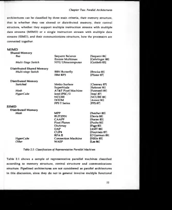
architectures can be classified by three main criteria, their memory structure, that is w hether they use shared or distributed memory, their control structure, whether they support multiple instruction streams with multiple data streams (MIMD) or a single instruction stream with multiple data streams (SIMD), and their communications structure, how the processors are connected together.
M IM D
Shared Memory
Bus Sequent Balance [Sequent 86] Encore Multimax [Gehringer 88] Multi-Stage Switch NYU Ultracomputer [Gottleib 83] Distributed Shared Memory
Multi-stage Switch BBN Butterfly [Brooks 85] IBM RP3 [Pfister 87] Distributed Memory
Switched Meiko Surface [Chesney 87] SuperNode [Refenes 90] Mesh AT&T Pixel Machine [Potmesil 89] HyperCube Intel iPSC/2 [Intel 87]
NCUBE [NCUBE 88] DOOM [Annot 90] FPS T Series [FPS87]
S IM D
Distributed Memory
[image:22.431.35.370.8.417.2]Mesh MPP [Batcher 80] BLITZEN [Davis 88] CAAPP [Foster 83] Pixel Planes [Fuchs 85] DisArray [Page 83] DAP [AMT 88] CUP4 [Fountain 87] RPAII [O'Gorman 89] HyperCube Connection Machine [Hillis 85] Other WASP [Lea 86]
Table 2.1: Classification o f Representative Parallel Machines
Table 2.1 shows a sample of representative parallel machines classified according to memory structure, control stru ctu re and communications structure. Pipelined architectures are not considered as parallel architectures in this discussion, since they do not in general involve multiple functional
units, rather they use parallelism within a single functional unit. In the following sections these architectural structures will be described in more detail, and the various design tradeoffs associated w ith them will be discussed.
2.2.1 M em ory Structure
As mentioned above all parallel architectures include m ultiple processors each of which can perform one operation at a time. Ideally each of these processors would have its own path to memory, such that all processors could access any piece of data anywhere in memory in the same amount of time.
This idealised model is similar to the P-RAM model [Gibbons 88] used by the theoretical community. In practice however it is not a feasible arrangement, because as the number of processors increases the am ount of hardware resources required to implement it becomes uneconomic.
2.2.1.1 Ideal Shared Memory Machine
To implement an ideal shared memory machine, there m ust be a separate path from every processor to memory, so that there is no contention for memory paths, and thus no delays w hich m ight affect computational efficiency. The memory must be able to provide simultaneous access for every path. This involves the use of memory devices with o n e port for every processor.
Chapter Two: Parallel Architectures
processors, would require a memory with a thousand ports.
Each port into a memory device requires its own set of input/output pins. A one thousand port memory would require at least one thousand pins, which is well beyond the current state of the art. Within the memory device each port requires access to every cell within the memory array. This means there must be separate data busses to every memory cell for every port. As the number of ports is increased the amount of silicon area taken up with wires will at some point overtake that used for memory cells. These factors make the construction of memories with very large numbers o f ports uneconomic, and this makes the idealised shared memory machine impractical.
Hillis [Hillis 85] argues that it is unreasonable to expect that such an idealised system could ever be constructed, since it ignores the fundamental laws of physics, in that it assumes information can travel in unit time from any point to any other, regardless of the size of the system. He argues that any useful model must take these fundamental truths into account.
The shared memory model is however conceptually elegant and simple, and many existing designs do provide such a model. In the absence of memory devices with very large numbers of ports designers have developed compromise solutions which attempt to balance hardw are resources and com putational efficiency. These solutions can b e divided into three categories, shared memory, distributed shared m em ory and distributed memory systems.
2.2.1.2 Shared Memory
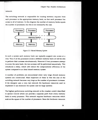
Shared memory systems are an attempt to implement a model as close as possible to the ideal shared memory machine, w here all processors can simultaneously access any parts of memory with equal latency, but without the use of memory devices with very large numbers of ports. Figure 2.2 shows a typical shared memory system. It consists of a number of processors, connected to a number of separate memory banks by a memory switching
network.
[image:25.431.30.364.5.414.2]The switching network is responsible for routing m em ory requests from each processor to the appropriate memory bank, so that each processor has access to all of memory. In this diagram the number of memory banks equals the number of processors, but this is not necessarily the case.
Figure 2.2: Shared Memory System
In such a system each memory bank can typically support one access at a time. Thus if all the processors access a different memory bank all will be able to perform their accesses simultaneously. However if two processors attempt to access the same bank, the two accesses will be performed sequentially. This introduces a delay, which will reduce the computational efficiency of the system compared to an ideail shared memory system.
A number of problems are encountered when very large shared memory systems are constructed. Most important of these is that the size of the switching network becomes very large as the number of processors increases. If the designer uses a very fast network the hardware resources used to implement it can dominate the system cost for large systems.
The highest performance switching network is the crossbar switch (described in section 2.2.2.2) which can provide a separate path from every memory bank to every processor. This network requires hardware resources which scale as the square of the number of processors. Since the hardware resources
14
\
Chapter Two: Parallel Architectures
used to implement the processors themselves scale linearly, it can be seen that for a large number of processors the resources used to implement the memory switch will dominate the system cost.
If a less resource intensive but slower network is used, it w ill increase the delays introduced by the communication system, which w ill in turn reduce the computational efficiency of the system. Whatever netw ork is used it will inevitably introduce some delay into each memory access and this can reduce the sequential instruction rate of each processor and thus reduce the peak computational power of the system. This becomes increasingly true as the number of processors, and the size of switch and/or the contention for the limited available switch bandwidth increases.
Because of these factors shared memory systems of this kind are generally limited to a relatively small number o f processors. Typical commercially available systems of this type use less than fifty processors.
2.2.1.3 Distributed Shared Memory
The key to allowing more processors to be used in shared memory systems is to reduce the bandwidth requirement of the interconnection network, and thus allow slower networks, which use fewer resources, to b e used. The key to achieving this is the observation that access to memory is not random, but structured.
Processors spend much o f their time accessing relatively few memory locations, which are often close together, a phenomenon know n as locality of reference. A rule o f thumb is that programs spend 90% of their time accessing 10% of their memory, known as the 90/10 rule [HenPat 90].
If the commonly accessed code and data for each processor w as stored locally to that processor then it would spend most of its time accessing its local memory. By allowing the processor to access its local m em ory directly without needing to go through the memory switch, m ost accesses would be
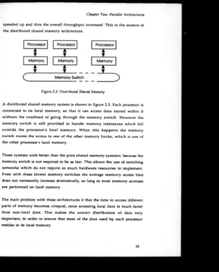
speeded up and thus the overall throughput increased. This is the essence of the distributed shared memory architecture.
Figure 2 3 : Distributed Shared Memory
A distributed shared memory system is shown in figure 2.3. Each processor is connected to its local memory, so that it can access data stored within it without the overhead of going through the memory switch. However the memory switch is still provided to handle memory references which fall outside the processor's local memory. When this happens the memory switch routes the access to one of the other memory banks, which is one of the other processor's local memory.
These systems scale better than the pure shared memory systems, because the memory switch is not required to be as fast. This allows the use of switching networks which do not require as much hardware resources to implement. Even with these slower memory switches the average m em ory access time does not necessarily increase dramatically, so long as most memory accesses are performed on local memory.
[image:27.430.45.362.6.400.2]Chapter Two: Parallel Architectures The distribution of code and data may be performed by sophisticated system software which dynamically migrates segments of code and data to processors w hich require them. Alternatively complex caching hardw are can be provided which performs the same function. Most commonly however it is the job o f the programmer to ensure the programs are divided up appropriately amongst the different processors.
The necessity for programmers to distinguish between local and non local m em ory goes against the basic principle of the idealised shared memory machine. However, as noted by Hillis [Hillis 85], it is probably an inevitable feature of any large real machine.
2.2.1.4 Distributed Memory
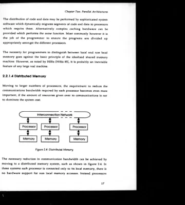
[image:28.433.43.404.6.407.2]M oving to larger numbers of processors, the requirement to reduce the communications bandwidth required by each processor becomes even more important, if the amount of resources given over to communications is not to dominate the system cost.
Figure 2.4: Distributed Memory
The necessary reduction in communication bandwidth can be achieved by moving to a distributed memory system, such as shown in figure 2.4. In these systems each processor is connected only to its local memory, there is no hardware support for non local memory accesses. Instead processors
cooperate on problems by passing messages over a separate processor interconnection network.
The key to distributed memory systems is the assum ption that the application programmer can pre-distribute programs in such a way that very little communication will be required between processors. Assuming this is the case, the interconnection network can afford to be relatively slow, since it does not have to support memory accesses, and thus does not have to offer the low latency this implies.
The m essage passing approach provides the potential to hide the long intercommunications latencies by scheduling another process while the communication is taking place. The Transputer [Shepard 87] for example makes u se of so called parallel slackness or excess parallelism, by running more than one process on each processor. Ideally there will always be at least one process ready to run, while others are waiting for communications.
The assumption of distributability restricts the classes of applications that can be successfully mapped onto distributed memory machines. However for applications which do map, distributed memory machines are very resource efficient architectures, even for systems with relatively small numbers of processors, since they require less resources to be used for interconnection.
Distributed memory systems can scale very readily, because the resources needed b y their communications networks tend not to increase as quickly as higher performance networks. This makes such systems ideal for massively parallel applications where hundreds or even thousands of processors are to be connected together.
Chapter Two: Parallel Architectures
program. Despite this however, the scalability of distributed memory systems has resulted in them constituting the bulk of existing parallel architectures.
2.2.2 Interconnection Sch em es
All parallel architectures require some form of interconnection mechanism, either to route data from memory to processors, in the case o f the shared memory systems, or to route data from processor to processor in the case of the distributed memory systems. A wide variety of designs have been used to im plem ent these netw orks, each exh ib itin g differen t perform ance characteristics and resource requirements.
There are three main characteristics associated with these communications networks: throughput, latency and complexity. The throughput refers to the maximum rate that data can be passed through the network. Latency refers to the time that each packet of data takes to complete its journey from source to destination. The complexity of the network is the amount o f resources required to implement it, and perhaps more im portantly how those resources increase as the size of the machine increases.
Initially it might appear the throughput and latency are simply two ways of measuring the same thing, since if each piece of data is delivered more quickly, the total amount of data delivered in any given time must also be higher. H ow ever most systems transfer many pieces o f information simultaneously with each one spending some time in transit.
The maximum throughput T in packets per second is given by
T * PT / L
Where L is latency in seconds per packet of data, and PT is the maximum number of packets in transit at any instant.
An ideal system will maximise throughput while minimising latency, but in practice m any systems will trade throughput for latency or vice versa. The network used in a given system will depend on the relative importance of these parameters for that system.
Shared m em ory systems place the highest burden on the network system because it is used for all memory references. This means that the network needs to b e capable of transferring data at a rate comparable to the total data transfer rate of all the processors combined. Also since the processor will usually b e suspended waiting for each memory reference, the network must have a latency comparable to a single processor memory cycle, otherwise processors will lie idle, and reduce the computational efficiency of the system.
Distributed shared memory systems reduce the total required throughput of the netw ork, since not all memory references go through the network. However they retain a requirement for fairly low latency, as while non local memory accesses are performed the processor will usually be idle.
Fully distributed systems place least burden on the interconnection network, since they remove the need to support memory references at all, using software controlled data passing instead. In particular distributed systems can tolerate q u ite high latency, by utilising excess parallelism to hide communication delays. However because distributed systems tend to make use of large numbers of processors, the total throughput of the network must be high, and must scale with the number of processors attached.
2.2.2.1 Bus Based Systems
The sim plest and most common interconnection scheme is the bus. This consists of a set of shared lines that connect all the devices together as shown in figure 2.5. Bus systems have very low minimum latency, since data can be transferred directly from source to destination without going through any interm ediate stages. They are also very straightforw ard to construct,
Chapter Two: Parallel Architectures requiring very few resources, which grow linearly with the number of devices connected. This low complexity allows the construction of extremely high speed busses, using relatively few resources, which can sometimes outperform theoretically superior systems.
However busses ultimately have a fixed, even if potentially quite large, total throughput. As the number of processors increases, and the total network traffic approaches the available throughput, contention for the bus becomes an increasing problem, which in turn increases the average communication latency.
The very low minimum latency of busses makes them ideal for shared memory systems, where latency is particularly critical. However their fixed total throughput means that the number of processors that can be supported is relatively low. Typical currently available commercial systems use up to thirty processors.
2.2.2.2 Connection Networks
One way to increase throughput over the bus is to move to a system that can perform more than one transfer at one time. This requires the network be made up of m any isolated sections, each of which are capable of transferring data independently of the others. These sections must then be interconnected either statically or dynamically to allow data to flow from one section to another, and so move from source to destination.
Figure 2 5 Bus Interconnection
Directly C o n n e c t e d Networks
The simplest class of such networks are the directly connected networks. In these each node is permanently connected to a subset of other nodes. These nodes are in turn connected to other nodes such that all nodes are connected either directly or indirectly.
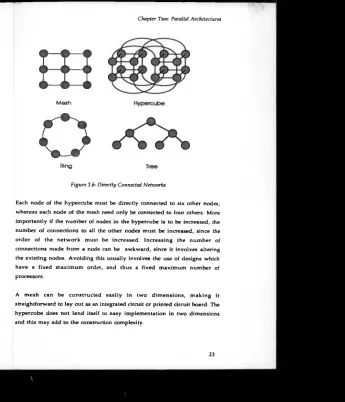
There are a num ber of possible topologies that can be used in this class of networks, and som e of the most common of these are shown in figure 2.6. There are two principal classifications used for directly connected networks, namely their order and their diameter. The order of a network refers to the number of nodes that each node is directly connected to. The diameter of a network is the maximum distance, measured in nodes, between any two nodes.
The networks can be broken down into two main sub-categories, fixed order networks, that scale by increasing their diameter, and variable order networks which scale by increasing their order (usually accompanied by an increase in diameter). The most common form of variable order networks are hypercubes, w hose order is equal to their number of dimensions.
Different topologies may be used to optimise the complexity and latency of the network. Latency is approximately proportional to the average number of stages that the data must pass through en route from source to destination, which in turn is related to the network's diameter.
For example a sixty four node system might be arranged as an eight by eight mesh or a six dimensional hypercube. The diameter of the mesh is fifteen, whereas the diam eter of the hypercube is only six. Thus the latency of data transfers for the hypercube will be significantly less than for the mesh. However the hypercube contains 196 wires compared to the mesh's 112 w ires, so the hypercube will require more interconnection resources to construct.
Chapter Two: Parallel Architectures
m
M e sh
[image:34.432.31.376.8.410.2]O
R ingFigure 2.6: Directly Connected Networks
Each node of the hypercube must be directly connected to six other nodes, whereas each node of the mesh need only be connected to four others. More importantly if the number of nodes in the hypercube is to be increased, the number of connections to all the other nodes must be increased, since the order o f the netw ork must be increased. Increasing the num ber of connections made from a node can be awkward, since it involves altering the existing nodes. Avoiding this usually involves the use of designs which have a fixed maximum order, and thus a fixed maximum number of processors.
A m esh can be constructed easily in two dim ensions, m aking it straightforward to lay out as an integrated circuit or printed circuit board. The hypercube does not lend itself to easy implementation in two dimensions and this may add to the construction complexity.
All the directly connected networks have a total throughput, which scales with the number of nodes, 0 (n ) in the case of the mesh and CXn log(n)) in the case o f the hypercube. This makes them ideal candidates for massively parallel distributed memory systems which can tolerate their relatively long latency. Constructional complexity varies from very low in the case of the mesh to moderate in the case of the hypercube, but even these are used in existing systems to connect many thousands of processors.
Switching Networks
The final class of interconnection schem es attem pts to produce a compromise between the low latency of the bus with the scalability and high throughput of the nearest neighbour systems. These are switching networks, which consist of single and multi-stage switches.
Single Stage Switching Networks - A fully connected single stage switch also known as a crossbar switch can directly connect any of a number of inputs to any of a num ber of outputs. Once connected data can flow unhindered from source to destination, making them ideal switch networks. Crossbars can provide throughput that scales linearly with the number of processors, however they have 0 (n 2) complexity and are therefore expensive to build for large numbers of inputs.
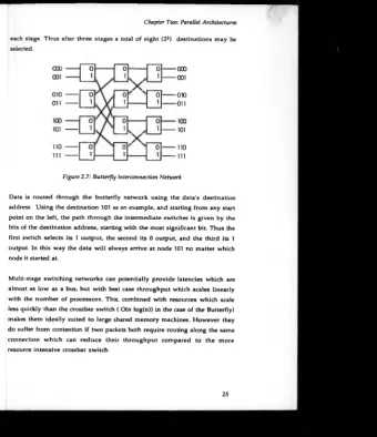
M ulti-Stage Sw itchin g Networks - can be designed in many different configurations [Feng 81], a typical example being the butterfly network shown in figure 2.7. In such networks data is routed from source to destination through a fixed number of intermediate stages, each of which consists of a number o f crossbar switches.
Chapter Two: Parallel Architectures
each stage. Thus after three stages a total of eight (23) destinations may be selected.
000
---001 ---
0
l
0
1
0
t
---000
---001
X
010
---Oil ---
0
1
0
1
0
1
---010
---Oil
0
1
0
1
0
1
101 ---
---101
X
n o —
[image:36.430.37.378.5.400.2]in —
0
1
0
1
0 ---110
— Ill
Figure 2.7: Butterfly Interconnection Network
Data is routed through the butterfly network using the data's destination address. Using the destination 101 as an example, and starting from any start point on the left, the path through the intermediate switches is given by the bits of the destination address, starting with the most significant bit. Thus the first switch selects its 1 output, the second its 0 output, and the third its 1 output. In this way the data will always arrive at node 101 no matter which node it started at.
Multi-stage switching networks can potentially provide latencies which are almost as low as a bus, but with best case throughput which scales linearly with the number of processors. This, combined with resources which scale less quickly than the crossbar switch ( CXn log(n)) in the case of the Butterfly) makes them ideally suited to large shared memory machines. However they do suffer from contention if two packets both require routing along the same connection w hich can redu ce their throughput compared to the more resource intensive crossbar switch.
2.2.3 Control Structure
The other principal classification for parallel architectures regards the distribution of control amongst the processing elements. This classification is due to Flynn [Flynn 66] who categorised all architectures into one of four groups.
These are shown below
Single Instruction Single Data (SISD) Single Instruction Multiple Data (SIMD) Multiple Instruction Single Data (MISD) Multiple Instruction Multiple Data (MIMD)
These classifications are divided into two parts, the first is concerned with the number of instruction streams, the other with the number of data streams. In a conventional von Neumann architecture the processor fetches one instruction at a time, providing a single instruction stream. Each instruction may perform an operation on one piece of data, providing one data stream. Thus a conventional sequential architecture would be classified as an SISD or single instruction single data.
All parallel architectures perform many operations at once, on many pieces of data, thus they all provide multiple data streams. However they may or m ay not allow multiple instruction streams. This provides two alternative approaches to building parallel systems, namely SIMD and MIMD.
2.2.3.1 SIMD M achines
Chapter Two: Parallel Architectures
[image:38.430.39.329.4.416.2]which has its own path to memory, allowing them all to simultaneously perform an operation on a piece of data stored in their local memory.
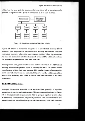
Figure 2.8: Single Instruction Multiple Data (SIMD)
Figure 2.8 show s a simplified diagram o f a distributed memory SIMD machine. T he Sequencer is responsible for fetching instructions from the instruction memory, where the user program resides. When the sequencer has read an instruction it is broadcast to all of the ALU's, which all perform the appropriate operation on their own local data.
The sequencer also generates the address of the data within the ALU's local memory that is to be operated upon. In this way all the ALU’s operate on the same location within their own memory. This can be thought of as operating on an array o f data where one element of the array resides within each of the ALU's local memory, and these machines are often referred to as array processors .
2.2.3.2 M IM D Machines
Multiple instruction m ultiple data architectures provide a separate instruction stream for each data stream. This arrangement is shown in figure 2.9. In this system each sequencer and ALU is grouped together to form what is essentially a conventional sequential processor. The sequencer reads the instructions from a combined program and data memory, and then instructs
its local ALU to perform the appropriate operation. Again the sequencer is responsible for generating the address of the data to be operated upon.
Figure 2.9: Multiple Instruction Multiple Data (M1MD)
An MIMD machine can be thought of as a collection of sequential machines, and they are often referred to as multi-computers. The important distinction is of course that they are connected together using one of the communication techniques described in the previous sections. In this way they can cooperate on the solution to a single problem.
2.2.3.3 Granularity
SIMD architectures have a significant resource efficiency advantage over MIMD architectures, in other words for a given amount of hardware resources an SIM D architecture can achieve more operations per second than an MIMD architecture. This is because each processor in an SIMD machine does not need its own sequencer and the resources that this requires. This means that m ore resources can be allocated to implement arithmetic units, rather than control logic.
Chapter Two: Parallel Architectures each processor m ust contain logic which im plem ents its instruction sequencer. Because of this it is generally inefficient to use MIMD processors with very small arithmetic units. SIMD architectures do not require logic to implement an instruction sequencer for each processor, which makes very fine grain architectures viable.
The finest grain processors are one bit or bit serial processors, and this is the type used by most SIM D architectures. Fine grain processors are arguably more efficient than coarser grain ones because their arithmetic units can be fully utilised on a w ider mix of operations. If for example each processor were equipped with a floating point arithmetic unit, it would lie idle for all operations that did not involve floating point operations. The silicon area used by the floating point unit would therefore not be being used effectively. By comparison the arithmetic unit of a bit serial processor will be used on every arithmetic operation.
Another advantage o f bit serial processors is that their arithmetic units do not suffer from the carry propagation delays associated with multi-bit designs. This allows single bit arithmetic units to operate at higher clock frequencies than multibit designs. The combination of these factors has led to the suggestion that single bit designs are inherently more efficient than other configurations [Hillis 85][Jesshope 89].
However it is a com plex trade off. In a uni-processor architecture the resource efficiency of the processor is relatively unimportant, since silicon area used to implement the processor cannot, in general, be more effectively used elsewhere to improve the performance of the system. In the case of a parallel architecture however any silicon area used to improve the performance of an individual processor could have been used to implement more processors. It therefore only makes sense to improve the performance of the individual processor in a parallel design w here the performance increase provided outweighs the disadvantage of having fewer processors.
29
\
The optimal solution for any particular architecture w ill depend on the application for which the architecture is intended. The higher the proportion of long word length or floating point operations that are expected the more likely it is that support for m ultibit operations w ill yield the best performance. Also if the total amount of potential parallelism is limited, it may not be possible to achieve improved performance from increasing the number of processors, so again coarser grain processors may produce the best performance.
So far single bit processors have dominated the SIMD field being used in the CLIP, DAP, MPP and Connection Machine. However recent trends suggest that multi-bit ALU’s may become more popular in future, with the CUP7a [Fountain 88] Connection Machine 2 [TMC 89] and the AMT DAP/C8 [AMT 90] all featuring multi-bit ALU designs.
2.2.3.4 Communication
Communication overheads have a large impact on the overall performance of a parallel system, and become increasingly important the more processors there are in the system. SIMD architectures have a clear advantage in this respect because they do not have to synchronise when communicating. For two processors in an MIMD machine to communicate, they must cooperate, such that each send operation performed by one processor is matched by an equivalent receive operation by the other. For this to take place the two processors must synchronise so that both are in the required state.
Chapter Two: Parallel Architectures This synchronisation process takes time, w hich adds to the overall communications delay, and so potentially affects the overall performance of the system. By comparison all processors in an SIMD system are controlled centrally by the sequencer, so that all processors are guaranteed to be in the same state at the same time. Thus when communication is required it can be performed without any need for synchronisation.
A restriction associated w ith many SIMD machines, particularly fine grain ones, is the limited num ber of efficiently supported communications patterns. This is caused partly by the sim ple d irectly connected interconnection networks they generally use, and partly by the requirement to perform the same operation on all processors. The combination o f these factors makes it very difficult to efficiently implement algorithms which require complex non-local communications patterns.
The main exception to this rule is the Connection Machine a fine grain SIMD machine which does allow arbitrary routing from one processor to any other. This increases the class of algorithms that can be efficiently processed significantly. Unfortunately the routing process is quite slow, and this can offset the efficiency advantage usually afforded to SIMD systems by not needing to synchronise.
2.2.3.5 Local Autonomy
The principal disadvantage of SIMD architectures is that they only operate efficiently for algorithms which process all their data identically. If an algorithm operates differently on different pieces of data the performance of the machine drops dramatically. In general the only way to implement algorithms that are not globally uniform on an SIMD machine is to disable certain processors so that they remain idle while a set of operations is being performed by the other processors. This clearly has a direct impact on the computational efficiency of the system.
Disabling processors works satisfactorily if there are a small number of alternatives, but becomes progressively less efficient as the number of alternatives increases. At the extreme where an algorithm wishes to perform a different operation on every pixel the performance of the whole system drops to that o f a sequential machine.
Some SIMD architectures such as the Connection Machine [Hillis 85] do allow a certain degree of local autonomy for each processor. This autonomy allows each processor to modify the globally broadcast instruction in certain ways to allow the processors to operate partially independently. In the Connection Machine the aspects of the instruction which can be altered are the address on which the instruction is to be performed, and the source of any non local data used in the operation. In general though most SIMD architectures do not allow this level of autonomy.
MIMD machines by comparison allow each processor to operate completely independently of all the others. This local autonomy means they can support algorithms which perform a different operation on each piece of data just as efficiently as one which operates identically on all pieces of data.
In summary SIMD machines are potentially highly efficient and scalable, but tend to only operate efficiently on a restricted class of algorithms. MIMD architectures are rather less efficient b u t can operate effectively on a wider variety of algorithms.
2.3 Existing Parallel Architectures
Chapter Two: Parallel Architectures
2.3.1 M IM D Systems
There are a large number of existing MIMD architectures. The reason for the proliferation of such m achines is most probably due to their ease of construction, which results from them being able to take advantage of existing microprocessor technology.
This use of existing components has allowed the designers of these machines to avoid the considerable expense and d ifficu lty associated with the developm ent of custom VLSI experienced by the designers of SIMD machines [Fountain 87]. It also allows the machines to take advantage of the vast investment in mainstream microprocessor technology.
The IPSC/2 for example has been upgraded from the Intel 80386 to use the new Intel i860 RISC processor, which provides almost an order of magnitude im provem ent in perform ance. It is unlikely that any of the relatively specialised producers of SIMD processors will have access to such up to date technology. For example the newest AMT DAP processor contains about 50,000 transistors compared to the i860's 1.2 million.
2.3.1.1 Shared M em ory Systems
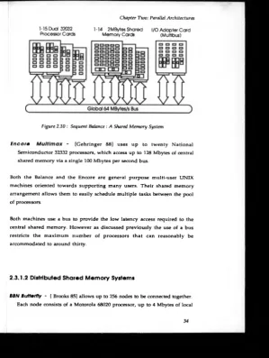
S equ ent B ala n ce - [Sequent 86] allows up to 30 National Semiconductor 32032 processors to share up to 32 Mbytes of central memory as shown in figure 2.10. The processors are connected to the memory system via a single 64 Mbytes per second bus.
1-15 D ud 32032 1-14 2MBytes Shared I/O Adapter C ard
[image:45.430.36.336.8.406.2]Processor Cards Mem ory Cards (Multibus)
Figure 2.10: Sequent Balance : A Shared Memory System
E n c o ro M u ltim a x - [G ehringer 88] uses up to twenty National Semiconductor 32332 processors, which access up to 128 Mbytes o f central shared memory via a single 100 Mbytes per second bus.
Both the Balance and the Encore are general purpose multi-user UNIX machines oriented towards supporting many users. Their shared memory arrangement allows them to easily schedule multiple tasks between the pool of processors.
Both machines use a bus to provide the low latency access required to the central shared memory. However as discussed previously the use of a bus restricts the maximum number of processors that can reasonably be accommodated to around thirty.
![Figure 2.1: Trends in VLSI Technology [Ruechardt 87]](https://thumb-us.123doks.com/thumbv2/123dok_us/9872237.488424/19.430.38.354.11.412/figure-trends-in-vlsi-technology-ruechardt.webp)