More Electric Aircraft Starter-Generator System with
Utilization of Hybrid Modulated Model Predictive Control
Seang Shen Yeoh, Tao Yang, Luca Tarisciotti, Christopher Ian Hill, Serhiy Bozhko, Pericle Zanchetta Department of Electrical and Electronic Engineering
University of Nottingham Nottingham, United Kingdom
Abstract—The current trend for future aircraft is the adoption of the More Electric Aircraft (MEA) concept. The electrical based starter-generator (S/G) system is one of the core ideas from the MEA concept. The PI based control scheme has been investigated in various papers for the permanent magnet based S/G system. Different control schemes are to be considered to improve the control performance of the S/G system. A type of non-linear control called Model Predictive Control (MPC) is considered for its capability to accomplish fast dynamic control performance. The Modulated Model Predictive Control (variant of MPC with an intrinsic modulator) was presented that showed considerably better control performance than the standard MPC. A control scheme is presented in this paper that utilises PI controllers for the outer loop and Modulated Model Predictive Control for the inner loop that covers operation for both starter and generator modes. Simulation analyses are carried out to compare between the proposed control and a full cascaded PI control scheme. The proposed control is also subjected to parameter variation tests for performance evaluation.
Keywords—model predictive control; starter generator; more electric aircraft
I. INTRODUCTION
The pressing environmental issues and increasing price of fossil fuels have been the drive to improve the weight and efficiency of aircraft. The More Electric Aircraft (MEA) concept is inline with this drive in addition to improving reliability, complexity, and costs [1, 2]. With the breakthrough of power electronics, it is possible to implement the starter-generator (S/G) scheme which is one of the core ideas of the MEA. An electrical machine can be used as a starter for the aircraft engine and function as a generator when the engine is self-sustained. The control design aspects has been reported for the MEA S/G system with a permanent magnet machine (PMM) in [3] and [4]. The designed controllers was implemented reasonably, however other control strategies should be considered to improve the control performance.
MPC has been considered as a solution for the control of power converters due to its fast dynamic performance, multivariable control, ease of constraint implementation and absence of signal modulation schemes. It can also adopted for minimum phase systems and handling non-linear dynamics [5, 6].
There are disadvantages of using MPC as well. Obviously since MPC is a model based control strategy, its
performance largely depends on the accuracy of the model. Furthermore, the lack of a modulation scheme results in a switching state applied across the whole switching period. It may therefore result in larger ripples in controlled variables with slow switching frequencies. Large ripples in current and voltage outputs from power converters have high harmonic content and hence have lower output power quality.
The use of MPC within drive systems has been covered in [5, 7-10]. Preindl implemented MPC for torque control of a PMM drive system [7]. Similar work was also done by Bolognani in [9]. The paper highlighted the use of MPC as a multivariable controller rather than being part of the conventional cascade control structure.
A recent variant of the MPC method was introduced with an intrinsic SVM scheme called Modulated Model Predictive Control (M2PC) with the aim of improving the performance of traditional MPC in terms of power quality. This method was proposed by Tarisciotti and studies have been performed in [11-15]. The aim of this method is to improve the output power quality of the system while maintaining the advantages of MPC with an intrinsic modulator. SVM was selected as the intrinsic modulator due to is efficient use of selected voltage vectors for finite switching power systems [12]. This resulted in less total harmonic distortion and switching losses from the output waveforms. The advantage offered by M2PC may be important in meeting power quality and voltage regulation standards such as MIL-STD-704F in aircraft power systems. M2PC has been investigated on IM based drive system with matrix converter [16]. In [15], M2PC has been used in a hybrid configuration with PI controllers for control of permanent magnet generator system.
In this paper, M2PC will be investigated as a control strategy for the inner current loop of the S/G power system. The outer loop will utilise PI based controllers. Together this will therefore form a hybrid control scheme. The hybrid control scheme will also be compared with the full PI control scheme done in [4]. The control scheme will be tested for both starter and generator modes at their respective operating conditions. Finally, system parameter variation will be conducted to determine the robustness of the hybrid control scheme.
II. POWER SYSTEM MODEL
The S/G system studied in this paper is shown in Fig. 1. iabc is the three phase currents, ωr is the rotor speed, and C
is the DC link capacitor. idc and Edc are the DC link current
and voltage respectively. A surface mounted PMM is joined to a two level Active Front-End (AFE) rectifier. The PMM drives the aircraft engine using electrical power from the grounds or auxilliary power supply to its start-up speed (about 10krpm) in starter mode. After that process, the engine proceeds to accelerate to higher speeds using its main power source which is jet fuel. At high speeds, the PMM functions as a generator to deliver electrical power to the main DC bus via the AFE. In generator mode, the aircraft engine is controlled externally and is assumed as an ideal speed source for the S/G system. The control scheme for this S/G system will be described in Section III.
abc
i r
ω
dc E
+
−
dc i
C
Fig. 1. S/G power system in study.
For the investigated S/G system, the model equations for MPC are mainly based on the PMM electrical equations (1) and (2):
( )
( )
d( ) ( )
d s d d q e q
t
di
v
R i
t
L
L
t
i
t
dt
ω
=
+
−
(1)(
)
( )
( )
q( )
( )
q s q q d d m e
di
v
R i
L
L i
d
t
t
t
t
ψ ω
t
=
+
+
+
(2)where Rs is the stator resistance, ψm is the mutual flux of the
machine, and ωe is the electrical speed. vd,q and id,q are the
AC voltages and currents of the PMM in dq frame. Ld,q are
the PMM inductances in dq frame. The derivative terms within these equations are discretised using the forward Euler method. It is assumed that the state variables stay constant during the sampling period, Ts.
( ) ( 1) ( ) s di t i k i k
dt T
+ −
≈ (3)
The discrete model for the PMM can therefore be derived as:
( )
( )
(
(
) ( )
)
( ) ( )
1
-d d d
d s d
s
q e q
L i k i k
v k R i k
T
Lω k i k
+
= + −
(4)
( )
( )
(
(
) ( )
)
( ) ( )
( )
1
q q q
q s q
s
d e d m e
L i k i k
v k R i k
T Lω k i k ψ ω k
+ −
= + +
+
(5)
vd,q can be related to the switching states of the AFE in
the dq frame, Sd,q, and Edc, by the following equation if the
impedance of the transmission line between the AFE and PMM is neglected:
, ,
d q dc dq d q
v =E k S (6)
kdq represents the dq transformation matrix where
three-phase variables can be transformed to dq frame:
( )
( )
( )
( )
( )
a ddq b
q
c
x k x k
k x k x k
x k
=
(7)
( )
(
)
(
( )
)
(
( )
)
( )
(
)
(
( )
)
(
( )
)
2 2
cos cos cos
2 3 3
2 2
3
sin sin sin
3 3
dq
k k k
k
k k k
π π
θ θ θ
π π
θ θ θ
− +
=
− − − − +
(8)
III.CONTROL APPROACH
[image:2.595.310.551.182.320.2]The advantage of MPC is its capability to predict future states over a fixed time horizon based on the control inputs and measured present states. For a power converter, this data is optimised within a cost minimisation function that decides the converter switching states for the next sampling period. The most suitable switching state is then selected and sent to the converter. Since a converter has a finite number of switching states, the optimisation stage and the time it takes can be reduced. The procedure of prediction and cost minimisation recurs for every sampling period [5, 6]. The flow diagram summarising the procedure can be seen in Fig. 2.
Fig. 2. Generalised MPC flow diagram.
The control of this S/G system is centred on field
oriented vector control where id and iq are regulated to
produce appropriate voltage vectors. Fig. 4 shows the
proposed hybrid PI-M2PC. Variables with superscript *
denote their respective reference values. |V| is the AC
magnitude voltage, v1 and v2 are the two active voltage
vectors while v01 and v02 are the two zero voltage vectors.
iqlim is the limit for the dynamic limiter that is derived from
[image:2.595.65.271.276.362.2]The control scheme for the S/G system can be divided into two parts; inner and outer loop. The choice of outer loop controller variables are as follows: the speed
controller, Ws, is used during starter mode and switches to
the DC link voltage controller, Widc, when operating in
generator mode. Droop control is employed together with
Widc to enable parallel source operation if required. The flux
weakening controller, Wfw, is always connected to ensure
control operation of the S/G system throughout the speed range. PI based controllers will be used for the outer loop.
The inner loops control id and iq using MPC as
explained earlier in this section. Due to a computational delay that exists in the practical system, the control output
calculated at time instant k can only be implemented at time
instant k+1. This delay can be circumvented by calculating
values two steps ahead. Equations (4) and (5) can be re-formed for two step prediction to give:
(
)
(
)
(
)
(
)
(
)
(
)
1 1
1
2 1
1
e s q
s s d
d d
d
q
d
s d
d
k T L i k R T i k
i k i k
L L
T v k L
ω + +
+
+ = − + + + +
+
(9)
(
)
(
)
(
)
(
)
(
)
(
)
(
)
1 1 1
1 2
1 1
s s q e s d
q
q q
q
s q m e s
q q
d
L
R T i k k T i k
i k
L L
i k
T v k k T
L L
ω
ψ ω
+ + +
− + + −
+ =
+ +
+ −
(10)
Now that the model equations are established, the cost
function, gMPC, can be defined as:
(
)
(
)
* *
2 2 i
M d d q q
i PC
g = i −i k+ + i −i k+ (11)
The currents are predicted considering all possible switching states. In this study a two-level converter is utilised and so as such eight switching states are possible.
The switching state for k + 2 that gives the smallest cost
function is selected and applied at the next sampling period.
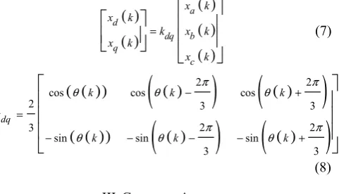
A. Modulated Model Predictive Control
In general, M2PC has similar prediction pattern to the
MPC except with the addition of modulation stage for SVM. Since SVM is used for the modulation scheme, two
active voltage vectors (v1, v2) are required for M2PC
operation. The two active vectors are designated from all the possible vector pairs by means of a modified cost function that takes into account the voltage, current, and
duty cycle predictions. The duty cycles, d determine the
appropriate time ratio for the four selected vectors (v1, v2,
v01, v02) within each sampling period, as shown in Fig. 3.
Finally, the appropriate switching states are to be applied
over a series of modulation steps, ms.
s
T
0 s d T
02
v
01
v
v
1v
2v
2v
1v
010.250.5 0.5 0.5 0.5 0.50.25 1 s
d T
2 s
d T d T0 s d T0 s
1 s
d T d T2 s
a
v
b
v
c
v
dc
E
s
T
s
T dc
E
dc
[image:3.595.346.503.79.173.2]E
Fig. 3. M2PC typical switching pattern [11].
The two active vectors for SVM are to be predicted based on (9) and (10), and these will be used to determine ii
d,q(k+2) and ijd,q(k+2). The variables with superscript i and
j use switch vectors in the order of [1,2,3,4,5,6] and
[2,3,4,5,6,1] respectively. (4) and (5) are utilised to
calculate the zero vector currents, i0
d,q(k+2) when vd,q = 0.
Equation (6) can then be re-arranged to give:
1 2
* i j
d dc d d
v =E
d S +d S
(12)1 2
* i j
q dc q q
v =E
d S +d S
(13)where d1 and d2 are the duty cycles for v1 and v2
respectively. The type of M2PC used in this study is based
on the dead beat control variation [11]; hence the voltage
references for the model also has to be predicted. vd,q* can
then be predicted to be equal to the voltage change across the inductances:
(
)
(
)
* 1
1 d d
d
s
i k L
v k
T
Δ +
+ = (14)
(
)
(
)
* 1
1 q q
q
s
i k L
v k
T
Δ +
+ = (15)
where
(
1)
0(
1)
*d d d
i k i k i
Δ + = + − (16)
(
)
0(
)
*1 1
q q q
i k i k i
Δ + = + − (17)
The zero vector duty cycle, d0, can then be determined
with:
0 1 1 2
d = −d −d (18)
M2PC requires two cost functions for the two active
vectors:
(
)
(
)
2
*
1
*
2 2
i i
M PC d d q q
g = i −i k+ + i −i k+ (19)
(
)
(
)
2
* *
2 2 2
j j
d d q q
M PC
g = i −i k+ +i −i k+ (20)
Together with d1 and d2, the overall cost function, gM2PC, is
the sum of the two cost functions:
2 1 2 1 2 2 2
M PC M PC M PC
g =d g +d g (21)
The switching states of Si
d,q and Sjd,q that generates the
smallest g will therefore be applied in the three-phase frame
accodring to the duty cycles of d1 and d2 using the
*
d i
*
q
i Sabc
Modulated Model Predictive Control
1
z−
DSP delay
M
odel
Pre
dic
tion
Co
st
F
un
cti
on
SVM
1, 2
v v
01, 02
v v
,
,
( 2), ( 2) i d q
j d q i k i k + + *
d i
*
q i
*
| |V
| |V
( ), ( )
d q
i k i k
*
r ω
r ω
dq abc
abc
i
2 2 lim maxq d
i = i −i
( ) fw
W z
( ) s W z
1
− ( 2),
( 2) d
q v k v k + +
| |V
dc i
( ) idc
W z
dc
E *
dc i
Droop
[image:4.595.95.537.74.266.2]To AFE
Fig. 4. Hybrid PI – M2PC scheme.
B. Angle Compensation
For high speed drive systems, [10] mentioned that the
electrical angle, θ, has to be compensated. The reason is
that θ is proportional to the machine rotor position, θr, and
therefore there would be a difference between the actual and predicted rotor position depending on the operating
speed. In order to reduce this error, θr has to be
compensated 1.5 sample periods ahead in order to obtain the mean rotor position after one sample delay. This can be represented by:
(
k 1)
1.5p r( )
k Ts( )
kθ + = ω +θ (22)
IV.RESULTS AND ANALYSIS
[image:4.595.310.535.472.706.2]After having derived the control structure, it is tested with a non-linear Matlab®/Simulink® model of the S/G system. The system parameters used are given in Table 1. The modulation step is the ratio between the PWM carrier signal frequency and sampling frequency. The modulation frequency is the rate at which the control signals are sampled. The full PI control scheme designed in [4] was used as a benchmark model.
Table 1. System parameters.
Parameter Value
Stator resistance, Rs 1.058mΩ
Stator inductance in rotating frame, Ld =
Lq
99µH
Pole pairs, p 3
Magnet flux-linkage, ψm 0.03644Vs
Rated power, Prated 45kW
Combined machine and engine inertia, J 0.103kgms2
DC bus capacitance, C 1.2mF Sampling period, Ts 62.5µs
Modulation period, Tm 625ns
Modulation step, ms = Tm/Ts 100
A. S/G Operation with Hybrid Control
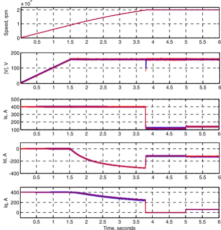
Fig. 5 shows the responses of the key state variables during starter mode. The speed reference is set at 20krpm.
FW was operational when |V| reached its reference value
of 155V by id injection into the machine, as clearly seen
in the simulation results from t ~ 1.5s.
Once the S/G system reached steady state, a load, TL,
of 10Nm was applied at t = 5s. The controlled variables
|V| and ωr, which use outer loop PI based controllers,
have no steady state error after the TL was applied due to
the integral terms within their respective regulators. Using
the hybrid PI-M2PC scheme, significant dq current ripple
reduction was observed throughout the simulation due to
the use of M2PC as part of the control structure.
Fig. 5. Time domain simulation in starter mode up to 20krpm between the full PI (blue) and hybrid PI-M2PC scheme (red).
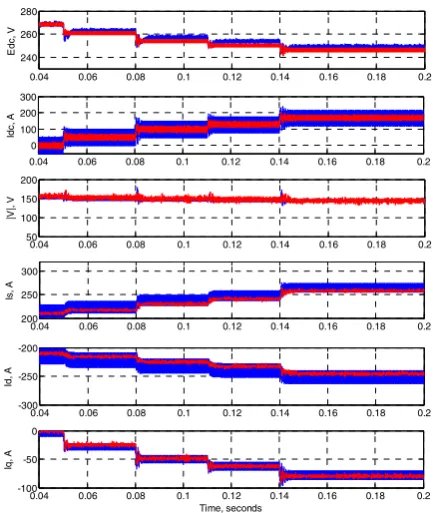
Fig. 6 shows the key state variable responses using the two control schemes in generator mode. During this
0.5 1 1.5 2 2.5 3 3.5 4 4.5 5 5.5 6 0
1 2
x 104
S
p
e
ed,
r
p
m
0.5 1 1.5 2 2.5 3 3.5 4 4.5 5 5.5 6 0
100 200
|V
|,
V
0.5 1 1.5 2 2.5 3 3.5 4 4.5 5 5.5 6 100
200 300 400 500
Is
, A
0.5 1 1.5 2 2.5 3 3.5 4 4.5 5 5.5 6 -400
-200 0
Id
, A
0.5 1 1.5 2 2.5 3 3.5 4 4.5 5 5.5 6 0
200 400
Time, seconds
Iq
[image:4.595.47.284.586.714.2]simulation the DC bus accepted load demands of 50A, 100A, 130A, and 170A in 0.03s intervals. Both of the control schemes were able to function with the subjected electrical loads at 32krpm. Significant reduction in the
current and |V| ripple was observed when using the hybrid
PI-M2PC. When the electrical loads were applied, there
was almost zero difference in the steady state ripple for
Edc. It can be seen that there was a more underdamped
response for all of the state variables when using the
[image:5.595.317.541.71.218.2]hybrid PI-M2PC scheme.
Fig. 6. Time domain simulation in generator mode operating at 32krpm between the full PI (blue) and hybrid PI-M2PC scheme (red).
B. Parameter Variation
For model based controllers such as MPC, it is important to assess the robustness of the technique towards parameter changes in the power system, especially if there are no parameter observer algorithms to adapt to the changes. Therefore, in order to test the robustness of the hybrid control scheme, parameter variation was introduced within the simulation model. Parameters that could change in actual drive systems due
to operating temperature or other factors such as Rs, Ld,q,
ψm, and C were assessed. Any significant changes in the
state variables could then be observed through the dq
currents along with the parameter difference from its nominal value.
Fig. 7 shows the iq response when Rs was altered by 5,
10, 40, 70, and 100 times its nominal value (1.058mΩ).
The figure also shows the responses when subjected to a
step in electrical load of 10kW at t = 0.08s. This was
included in order to determine any differences before and after load impact. It can be seen that there was a difference in steady state values that are increasing (in the
negative direction) as iq had to compensate for the higher
Rs. Even at 100 times the nominal value of Rs, the control
was still stable.
Fig. 7. iq responses with different values of Rs operating at 32krpm.
Both Ld and Lq were reduced simultaneously in
increments of 5% of their nominal value with the same
load conditions as the Rs variation test. Both dq currents
were found to be affected by the change in inductance, as can be seen in Fig. 8. Large ripples can be seen when the
dq inductances were at 80% of the nominal value (99µH).
The variation in Ld and Lq affects the accuracy of the
model prediction and as such causes the different steady
[image:5.595.56.273.187.444.2]state values of id.
Fig. 8. id (top) and iq (bottom) responses with different values of
machine inductance operating at 32krpm.
ψm was reduced in increments of 5% of its nominal
value. Both of the dq currents were observed and are
shown in Fig. 9. The change of ψm resulted in different
steady state results for id due to the decrease of back-emf.
Less id was therefore required for FW. Large ripples were
observed at 80% ψm when operating without load. After
the load impact of 10kW, the large oscillations reduced
and stability was restored. Fig. 10 shows iq responses to
changes of C when reduced by 20% increments. The
reduction of C mainly affected Widc which explains the
oscillations.
Overall, the influence of L and ψm variation imposed
the most significant effect to the hybrid M2PC control
performance. A maximum change of 20% L or 25% ψm
was required before the controller became unstable. In applications where the actual system parameters can vary beyond this range, observers can be used for parameter estimation such as Luenberger observer and Kalman filter.
0.04 0.06 0.08 0.1 0.12 0.14 0.16 0.18 0.2 240
260 280
Ed
c
, V
0.04 0.06 0.08 0.1 0.12 0.14 0.16 0.18 0.2 0
100 200 300
Id
c
, A
0.04 0.06 0.08 0.1 0.12 0.14 0.16 0.18 0.2 50
100 150 200
|V
|,
V
0.04 0.06 0.08 0.1 0.12 0.14 0.16 0.18 0.2 200
250 300
Is
, A
0.04 0.06 0.08 0.1 0.12 0.14 0.16 0.18 0.2 -300
-250 -200
Id
, A
0.04 0.06 0.08 0.1 0.12 0.14 0.16 0.18 0.2 -100
-50 0
Time, seconds
Iq
, A
0.075 0.08 0.085 0.09 0.095 0.1
-60 -50 -40 -30 -20 -10 0 10 20
Time, seconds
C
u
rr
e
n
t, A
R R x 5 R x 10 R x 40 R x 70 R x 100
0.075 0.08 0.085 0.09 0.095 0.1
-300 -280 -260 -240 -220 -200
C
u
rr
ent
, A
0.075 0.08 0.085 0.09 0.095 0.1
-200 -100 0 100 200
Time, seconds
C
u
rre
n
t, A
100% 95% 90% 85% 80%
[image:5.595.317.537.342.504.2]Fig. 9. id (top) and iq (bottom) responses with different values of ψm
operating at 32krpm.
Fig. 10. iq responses with different values of C operating at 32krpm.
V. CONCLUSION
M2PC was investigated to assess its potential for
improving the control performance of the S/G system.
The M2PC scheme was derived and implemented for the
dq current loop. The outer control loops were controlled
using PI controllers. Angle compensation was therefore added as the model prediction was being affected by the
speed of the PMM. Overall, the hybrid PI-M2PC scheme
was found to be capable of S/G control operation. Moreover, it showed improvements in terms of reduced current ripple when compared to the conventional full PI control scheme. Parameter variation tests showed that the hybrid control performance was most susceptible to the
change of L and ψm within a variation of 20% and 25%
respectively. Parameter observers are required to compensate for possible parameter variations beyond that range. Future work would include experimental verification of the hybrid control scheme and implementation of full predictive control (Speed, FW, and DC link voltage as part of predictive control variables) for the S/G system.
Acknowledgement
The work in this paper has been funded by EU FP7 funding via the Clean Sky JTI (Systems for green Operations ITD).
References
[1] J. A. Rosero, J. A. Ortega, E. Aldabas, and L. Romeral, "Moving towards a more electric aircraft," Aerospace and Electronic Systems Magazine, IEEE, vol. 22, pp. 3-9, 2007. [2] P. Wheeler and S. Bozhko, "The More Electric Aircraft:
Technology and challenges," Electrification Magazine, IEEE, vol. 2, pp. 6-12, 2014.
[3] S. Bozhko, Y. Seang Shen, G. Fei, and C. Hill, "Aircraft starter-generator system based on permanent-magnet machine fed by active front-end rectifier," in Industrial Electronics Society, IECON 2014 - 40th Annual Conference of the IEEE, 2014, pp. 2958-2964.
[4] S. S. Yeoh, F. Gao, S. Bozhko, and G. Asher, "Control design for PMM-based starter generator system for More Electric Aircraft," in Power Electronics and Applications (EPE'14-ECCE Europe), 2014 16th European Conference on, 2014, pp. 1-10.
[5] P. Cortes, M. P. Kazmierkowski, R. M. Kennel, D. E. Quevedo, and J. Rodriguez, "Predictive Control in Power Electronics and Drives," Industrial Electronics, IEEE Transactions on, vol. 55, pp. 4312-4324, 2008.
[6] J. Rodriguez, M. P. Kazmierkowski, J. R. Espinoza, P. Zanchetta, H. Abu-Rub, H. A. Young, and C. A. Rojas, "State of the Art of Finite Control Set Model Predictive Control in Power Electronics," Industrial Informatics, IEEE Transactions on, vol. 9, pp. 1003-1016, 2013.
[7] M. Preindl and S. Bolognani, "Model Predictive Direct Speed Control with Finite Control Set of PMSM Drive Systems," Power Electronics, IEEE Transactions on, vol. 28, pp. 1007-1015, 2013.
[8] M. Preindl and S. Bolognani, "Model Predictive Direct Torque Control With Finite Control Set for PMSM Drive Systems, Part 1: Maximum Torque Per Ampere Operation,"
Industrial Informatics, IEEE Transactions on, vol. 9, pp. 1912-1921, 2013.
[9] S. Bolognani, L. Peretti, and M. Zigliotto, "Design and Implementation of Model Predictive Control for Electrical Motor Drives," Industrial Electronics, IEEE Transactions on, vol. 56, pp. 1925-1936, 2009.
[10] M. Hyung-Tae, K. Hyun-Soo, and Y. Myung-Joong, "A discrete-time predictive current control for PMSM," Power Electronics, IEEE Transactions on, vol. 18, pp. 464-472, 2003.
[11] L. Tarisciotti, P. Zanchetta, A. Watson, J. Clare, M. Degano, and S. Bifaretti, "Modulated Model Predictive Control (M2PC) For A 3-Phase Active Rectifier," Industry Applications, IEEE Transactions on, vol. PP, pp. 1-1, 2014. [12] L. Tarisciotti, "Model Predictive Control for Advanced
Multilevel Power Converters in Smart-Grid Applications," PhD, University of Nottingham, 2014.
[13] L. Tarisciotti, P. Zanchetta, A. Watson, J. Clare, S. Bifaretti, and M. Rivera, "A new predictive control method for cascaded multilevel converters with intrinsic modulation scheme," in Industrial Electronics Society, IECON 2013 - 39th Annual Conference of the IEEE, 2013, pp. 5764-5769. [14] L. Tarisciotti, P. Zanchetta, A. Watson, S. Bifaretti, and J. C.
Clare, "Modulated Model Predictive Control for a Seven-Level Cascaded H-Bridge Back-to-Back Converter,"
Industrial Electronics, IEEE Transactions on, vol. 61, pp. 5375-5383, 2014.
[15] Y. Seang Shen, Y. Tao, L. Tarisciotti, S. Bozhko, and P. Zanchetta, "Hybrid modulated model predictive control for the more electric aircraft generator system," in Electrical Systems for Aircraft, Railway, Ship Propulsion and Road Vehicles (ESARS), 2015 International Conference on, 2015, pp. 1-6.
[16] M. Vijayagopal, L. Empringham, L. de Lillo, L. Tarisciotti, P. Zanchetta, and P. Wheeler, "Control of a direct matrix converter induction motor drive with modulated model predictive control," in Energy Conversion Congress and Exposition (ECCE), 2015 IEEE, 2015, pp. 4315-4321.
0.075 0.08 0.085 0.09 0.095 0.1 -250
-200 -150 -100 -50
C
u
rr
e
n
t, A
0.075 0.08 0.085 0.09 0.095 0.1 -40
-20 0 20
Time, seconds
C
u
rre
n
t,
A
100% 95% 90% 85% 80% 75% 100% 95% 90% 85% 80% 75%
0.08 0.09 0.1 -40
-20 0 20
C
u
rre
n
t,
A
0.08 0.09 0.1 -40
-20 0 20
0.08 0.09 0.1 -40
-20 0 20
Time, seconds
C
u
rre
n
t, A
0.08 0.09 0.1 -40
-20 0 20
Time, seconds 40% C 80% C 100% C
![Fig. 3. M2PC typical switching pattern [11].](https://thumb-us.123doks.com/thumbv2/123dok_us/8663924.375656/3.595.346.503.79.173/fig-m-pc-typical-switching-pattern.webp)