Effect of particle and carbide grain sizes on a HVOAF WC-Co-Cr coating for the future application on internal surfaces: microstructure and wear
J. Pulsford1, S. Kamnis2, J. Murray1, M. Bai1, T. Hussain1
1 Faculty of Engineering, University of Nottingham, Nottingham, NG7 2RD UK 2Castolin Eutectic -Monitor Coatings Ltd, North Shields, NE29 8SE, UK
Abstract
The use of nanoscale WC grain or finer feedstock particles are possible methods of
improving the performance of WC-Co-Cr coatings. Finer powders are being pursued for the
development of coating internal surfaces, as less thermal energy is required to melt the finer
powder compared to coarse powders, permitting spraying at smaller stand-off distances.
Three WC-10Co-4Cr coatings, with two different powder particle sizes and two different
carbide grain sizes, were sprayed using a high velocity oxy-air fuel (HVOAF) thermal spray
system developed by Castolin Eutectic- Monitor Coatings Ltd., UK. Powder and coating
microstructures were characterised using XRD and SEM. Fracture toughness and dry sliding
wear performance at three loads were investigated using a ball-on-disc tribometer with a
WC-Co counterbody. It was found that the finer powder produced the coating with the
highest microhardness, but its fracture toughness was reduced due to increased
decarburisation compared to the other powders. The sprayed nanostructured powder had
the lowest microhardness and fracture toughness of all materials tested. Unlubricated sliding
wear testing at the lowest load showed the nanostructured coating performed best; however
at the highest load this coating showed the highest specific wear rates with the other two
powders performing to a similar, better standard.
1 Introduction
In many engineering applications wear is a life-limiting factor for various safety critical
components and one of the most extensively used types of wear resistant coatings are
industrial hard chromium or electrolytic hard chrome (EHC) [1]. However, due to the recent
introduction of REACH (Registration, Evaluation, Authorisation and Restriction of Chemicals),
legislations regarding the use of hexavalent chromium in the EU, the need for industry to
replace this process has risen. High velocity oxy fuel (HVOF) thermal sprayed coatings are a
deposition technology that can replace EHC coatings due to the fact that HVOF thermal spray
coatings have better wear and corrosion performance and a lower life cycle cost [2].
WC-Co-Cr coatings have been chosen as a good potential material for this application, as this material
displays wear resistance comparable to the widely used WC-Co but also offers an
improvement in corrosion resistance. However HVOF processes are limited by their line of
sight nature, meaning that spraying surfaces in tight confined areas is a challenge when
compared to traditional EHC processes. Applying coatings on internal surfaces in tight spaces
for complex geometries using most commercial HVOF systems is not feasible, due to the
dimensions of the spray torch and the stand-off distance required for optimal particle
temperature and velocity; therefore reducing the barrel length is necessary for operation in
smaller geometries.
Internal diameter (ID) HVOF thermal spraying is a modern technology developed with the aim
of mitigating these issues, operating at lower power levels but at the same time retaining high
kinetic energy allowing a greater range of internal surfaces to be effectively coated. ID HVOF
thermal spraying is a field that has been gaining the attention of researchers, with Lyphout
and Björklund successfully applying a WC-Co-Cr coating with a powder particle size
distribution of -31 + 5.5 µm on an internal surface of a pipe with a 200 mm ID using a newly
developed ID HVAF (High Velocity Air Fuel) system produced by UniqueCoat Technologies
(Oilville, USA). The resulting coating had a hardness of 900 (HV0.3) and a porosity of
results show that the mechanical properties of these internally sprayed coatings are inferior to
WC-Co-Cr coatings applied externally using current commercial High Velocity Oxy Liquid Fuel
(HVOLF) spray technologies as these coatings have been shown to have a microhardness of
over 1200 HV0.3 [4]. Therefore further development is required before ID HVOF systems can
compete with their externally sprayed equivalents.
As the temperature of the in-flight particles is strongly dependant on the length of the barrel,
using conventional feedstock powders with a shorter barrel length may result in particle
underheating, resulting in coatings with higher levels of porosity and lower hardness reducing
the corrosion and wear resistance of the coating [5]. To mitigate these effects, powders with
a reduced particle size range can be used as a smaller particle with a lower mass will
accelerate at a faster rate, as well as requiring less energy to reach its optimum temperature
when compared to larger, heavier particles of the same material. Along with this key
advantage, spraying finer powder feedstocks have been previously shown to produce coatings
with a lower porosity when compared to coarser grained powders [6]. Alongside these
materials, it has been reported that using nanostructured WC-Co-Cr feedstock powders
results in coatings with better mechanical properties and sliding wear resistance than their
coarse carbide grain counterparts, with Thakur and Arora producing a nanostructured
WC-Co-Cr coating with a microhardness of 1646 HV0.3, compared to a coarse grained coating
which had a microhardness of 1147 HV0.3 [7]. Therefore using either finer or nanostructured
WC-Co-Cr powders may be a method to counter the lower power, barrel length and standoff
distance present in ID HVOF thermal spray processes.
Although both finer and nanostructured WC-Co-Cr powder feedstocks have the potential to
improve coating properties, both materials have been previously shown to be more vulnerable
to decomposition of the WC phase. The mechanism for the decarburisation in WC based
cermet coatings has been studied and it has been shown that carbon loss occurs as follows.
The binder phase melts before the WC phase, due to its lower melting point. At this point WC
will begin to dissolve into the molten binder, after which carbon will begin to be removed by
the solution is rapidly quenched and the binder phase solution becomes supersaturated,
resulting in the release of W2C [8]. Simultaneously the formation of an amorphous or
nanocrystalline supersaturated solid cobalt, tungsten carbide solution or η phase carbide can
also take place meaning a binder phase of varying compositions may be observed throughout
the microstructure [9] As finer particles are more susceptible to overheating due to their lower
mass and nanoscale WC grains may dissolve more readily in the molten binder due to their
higher surface area to volume ratio compared to coarse WC grains, the likelihood of
decarburisation occurring by the above mechanism increases when spraying finer or
nanostructured powders. Therefore, when using these materials the optimisation of spray
parameters is the key to producing a coating with a high density of the WC phase.
In this study, an HVOAF (High velocity oxy-air fuel) spray system capable of operating with a
mixture of air and organic fuel gases developed by Castolin Eutectic Monitor Coatings Ltd.
(North Shields, UK) was used to spray three separate WC-Co-Cr powders with the same
composition but differing powder particle size ranges and carbide grain sizes. The
microstructures and the associated mechanical properties were studied. Unlubricated sliding
wear testing against WC-Co counterbody was used to study the effect of powder particle size
range or carbide size on the coating’s sliding wear resistance and as a means to test the
performance of the three coatings.
2 Experimental Methods
2.1 Feedstock materials
Three separate commercial WC-Co-Cr powders (H.C Starck Ltd, Munich, Germany) with the
same composition (WC - 10% Co - 4% Cr in wt.%) but differing carbide grain sizes and powder
particle size distributions were used in this study. The details of the powders are displayed in
Table 1; the MC-30 and MC-15 powders are stated by the manufacturer to have a medium
WC grain size, but differ in powder particle size range. The third feedstock powder NC-30
and powder particle size range on the coating microstructure, mechanical properties and wear
resistance can be compared.
2.2 HVOAF Coating deposition
All coatings were deposited onto 38.1 mm diameter x 6 mm discs of EN 1.4401 grade 316
stainless steel (16% Cr, 10% Ni and 2% Mo, in wt.%) for characterisation and wear testing
using a next generation HVOAF system capable of depositing coatings on internal surfaces
developed by Castolin-Eutectic Monitor Coatings Ltd [10]. This system uses an isentropic cone
shaped nozzle to accelerate the combustion gases to supersonic velocities reaching Mach 2.7
[11]. Prior to coating deposition all substrate materials used were cleaned and grit blasted to
maximise particle-substrate bonding. The spray parameters used in this study were chosen
based on data from previous optimisation studies. The torch uses air (60 – 500 SLPM) and O2
(50-170 SLPM) depending on the mode of operation, aiming for 100% stoichiometric
combustion.
2.3 Dry Sliding Wear Testing
Unlubricated sliding wear tests were carried out at room temperature (≈ 25 °C, relative
humidity ≈ 60 %) using a rotating ball on disc tribometer against a 94 % WC - 6 % Co ball with
a diameter of 9.5 mm (Dejay Distribution Ltd, Launceston, UK) that was replaced at the end
of each test. The details of the sliding wear rig are described elsewhere [12]. The experimental
parameters used during the sliding wear tests were selected with the aim of simulating typical
conditions for components in the aerospace industry that experience sliding wear.
Uninterrupted wear tests were run at loads of 96 N, 168 N and 240 N with a sliding distance
of 500 m and sliding speed of 0.05 m/s. These three loads were selected in order to simulate
a low, medium and high load environment to determine if the coatings experience a different
wear regime as conditions are changed. Prior to the wear test, the top surface of the coatings
were grinded and polished down to a 1 µm finish. Both the coating sample and the ball
The volume loss of each disc was determined using the profilometry method used in a number
of other studies [13, 14]; a surface profiler (Taylor Hobson Ltd, Leicester, UK) was used to
measure four line traces perpendicular to the sliding direction and from each of these the
cross-sectional area of material loss could be determined. These were averaged and
multiplied by the total track length to calculate the total volume of material lost. The specific
wear rate could then be calculated by dividing the total volume of material lost by the product
of the total distance slid and the load used. The wear of the WC-Co ball resulted in a near flat
surface and using the assumption that this represented the removal of a spherical cap of
material, Eq. 1 and Eq. 2 can be used to calculate the volume loss of the counterbody [15]:
𝑑 = 𝑟 − √(𝑟2− 𝑎2) (Eq.1)
∆𝑉 = 𝜋𝑑2(𝑟 −𝑑
3) (Eq.2)
Where ∆𝑉 represents the volume loss, 𝑟 the ball radius and 𝑎 the radius of the wear scar.
The morphology of the wear scar and fracture mechanisms were then examined in plain view
using a scanning electron microscope (Jeol 6490LV, Jeol Ltd., Japan), with optical microscopy
(Nikon Eclipse LV100ND, Nikon, Japan) used to image the WC-Co counterbody.
2.4 Coating Characterisation
X-ray diffraction (XRD) was performed on the feedstock powders and as-sprayed coatings
using a Siemens D500 with Cu Kα radiation (1.5406 Å) in the 20° ≤ 2θ ≤ 90° range to identify
the phases present in the powders and coatings. A step size of 0.02° and dwell time of 3 s
was used. Sections of the coating were cut from the bulk sample using a diamond tipped
precision cutting wheel; powder and coating cross-sections were then obtained by mounting
in a conductive mounting compound (Metprep Ltd, UK), ground with SiC papers down to 15.3
µm grit finish then finally were polished down to a 1 µm finish.
The powder morphologies and coating microstructures were imaged using SEM (JEOL
electron imaging (SE) and backscattered electron imaging (BSE). “The carbide grain size of
the feedstock powders, coating thickness and coating porosity were measured using image
analysis software to process a collage of five SE SEM images (Image J, National Institute of
Health, USA). Each image used for the porosity measurement covered an area of coating
approximately 420 µm in length and 270 µm in height, meaning the porosity measurement of
each coating was determined by analysing approximately along 2.1 mm of the coating length,
or 0.6 mm2 of the coating cross section.
The microhardness of the coatings was measured on polished cross-sections by using a
Vickers microhardness indenter (Buehler, Illinois, USA) at a load of 300 gf and a dwell time of
10 s; for each sample 6 indentations were made in the centre of the coatings running parallel
with the substrate. Fracture toughness of the coatings was measured by indenting on polished
cross sections with a 2.5 kgf load and measuring the crack lengths parallel to the substrate
using optical microscopy; cracks propagating from the left and right tips of the indent were
considered. The fracture toughness Kc was determined using the method described by Evans
and Wilshaw [16], shown in Eq. 3:
𝐾𝑐 = 0.079 ( 𝑃
𝑎3⁄2) log (
4.5𝑎
𝑐 ) (Eq. 3)
Where 𝑃 is the applied indentation load, 𝑎 is the indentation half diagonal and 𝑐 is the crack
length from the indent centre. This expression is only valid when 0.6 ≤ c/a ≤ 4.5; all
measurements of 𝑐 and 𝑎 were determined to fit within this range.
3 Results
3.1 Feedstock powder characterisation
SEM micrographs (Fig. 1) show that the MC-30 and NC-30 powders both exhibit a spherical
structure with some porosity; cross sectional images of these powders show that this
porosity is also present within the inner structure of the powder particles. The SE images of
suggesting that even the actual surface area of the MC-30 powder particles may be larger
than the NC-30 powder particles.
The MC-15 powder was observed to have a blocky, angular morphology with a lower visible
porosity both internally and externally; this difference was attributed to the different methods
of powder manufacture used (MC-15 was sintered and crushed while the other two powders
were agglomerated and sintered). The powders with the medium WC grain size MC-30 and
MC-15, and the nanostructured powder NC-30 were found to have a carbide grain size
between 1-2 µm and 200 - 400 nm respectively.
The XRD spectra in Figure 2 show that some differences in the phase composition between
the three powders exist. Aside from the primary WC and Co. fcc phases, additional phases
were detected within the MC-30 and MC-15 powders, with the diffraction peaks indicating
that these include the η-phase (W, Co, Cr) 6C or (W, Co, Cr)7C3 as seen by other
researchers [4]. However, these two phases are difficult to distinguish in XRD analysis due
to the fact that the two main diffraction peaks for these phases are very close to one another,
with peaks of the η-phase and (W, Co, Cr)7C3 being located at 2θ values of 42.4° and 42.5°
respectively. It can be observed that a degree of shifting of these peaks has occurred in the
MC-15 powder, possibly indicating that W or Co has dissolved into the (W, Co, Cr)7C3
phase, substituting itself for Cr in the lattice [4].
3.2 Coating Microstructure and Mechanical Properties
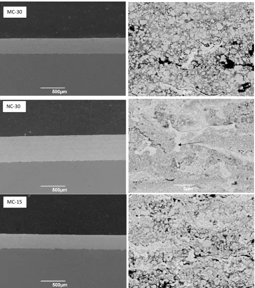
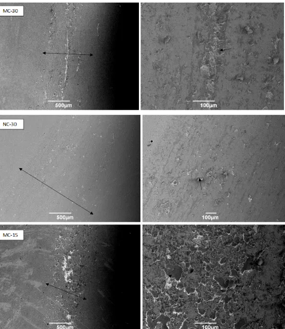
Low magnification images (see Figure 3) of the coatings show that all three coatings display
a macroscopically dense structure, with no large pores visible and no crack or delamination
at the coating-substrate interface. The coating thickness (see Table 2) can be seen to vary
between the coatings, with the nanostructured coating being considerably thicker. Porosity in
all three coatings is very low, with the MC-30 coating having the highest at a level of
approximately 0.53 ± 0.24 % and the coating sprayed with the finer powder MC-15 having
of the coatings. The MC-30 and MC-15 coatings both exhibit a very similar microstructure;
WC grains with irregular shape and size are surrounded by a metallic binder phase of
varying composition. Areas of the binder phase showing a brighter contrast indicate regions
in which the WC grains have dissolved into the matrix, with the brighter contrast being the
result of increased tungsten levels. Some of the WC grains residing in these W heavy
binder zones were observed to be surrounded by a “halo” of another phase displaying an
even brighter contrast, which has been confirmed by other researchers as being W2C [9].
This feature can be seen in larger numbers in the MC-15 coating, indicating that the finer
powder decarburised more during the spray process; this result is confirmed by the XRD
spectra in Figure 2. Alongside these phases, other areas of the binder phase exhibit a much
darker contrast in both the MC-30 and MC-15 coatings; these areas are not porosity but
have been shown by EDX analysis to be a Cr and Orich phase with a lower W composition
in comparison to other areas of the binder.
The NC-30 coating was found to have a different microstructure compared to the other two
coatings; due to the much smaller size of the WC grains they dissolve more readily in the
binder during the spray process, resulting in areas of tungsten heavy binder in which the
individual WC grains can no longer be seen due to dissolution. Small spots observed on the
image of an even brighter phase can be seen in some of these areas which indicate the
presence of W2C. The presence of the dark Cr rich phase seen in the other two coatings
was found to still be present in the NC-30 coating, however this phase was found to be less
common in the nanostructured coating.
The diffraction patterns given by XRD in Figure 2 indicate that W2C has formed in all three
coatings; therefore supplementing the SEM images and confirming that different degree of
decarburisation has occurred in all three coatings. The height of the W2C peaks in relation to
the WC peaks is significantly larger for the MC-15 coating, giving more evidence for
increased decarburisation compared to the other two coatings, in which the levels of W2C
the (1 0 0) peak of WC at 2θ = 35.6° and (1 0 1) peak of W2C at 2θ = 39.6° was calculated
for the three coatings using the method shown in other work [17] and the results are shown
in Table 2, which show that less carbon was retained in the MC-15 coating in comparison to
the other two, meaning that decarburisation was more severe when spraying this material
with the selected parameters. All three coatings show no detected peaks of the Co fcc,
η-phase and M7C3 phases that were found with the powder feedstocks.
Mechanical properties of the three coatings are shown in Table 2; the microhardness of the
MC-30 and MC-15 coatings were found to be at similar levels. The nanostructured NC-30
coating was found to have the worst mechanical properties of the three coatings tested, with
the lowest microhardness and fracture toughness at values of 1246 ± 58 and 3.62 ± 0.65
MPa.m0.5.
3.3 Dry sliding wear test
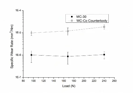
The specific wear rates of the coatings and WC-Co counterbodies at the three loads used
during the sliding wear testing are shown in Figures 4, 5 and 6. The MC-30 coating (Fig. 4)
was shown to perform similarly across the three loads tested, with the increased load only
resulting in heightened counterbody wear; this may suggest that the same mechanism of
wear is taking place at all loads tested. Although similar specific wear rates were measured
for the MC-15 coating (Fig. 6) at 96 N and 240 N, a slight increase was seen at 168 N. This
however is balanced out by reduced counterbody wear at this load, meaning the MC-15
coating wore out more aggressively in relation to the counterbody in comparison to the other
coatings at 168 N. The NC-30 coating (Fig. 5) displayed a different trend in comparison to
the other two coatings; the specific wear rate was almost an order of magnitude lower than
the others at 96 N, but with heightened load a large increase of wear was observed resulting
in this coating performing the worst at 240 N. This difference in performance in comparison
to the other coatings across the three loads may suggest that a separate wear mechanism is
taking place in the nanostructured coating, or that the inferior mechanical properties of this
The counterbody wear rates were an order of magnitude higher than those measured for the
coatings. As the load was raised the specific wear rate of the WC-Co counterbodies used
with the MC-30 and MC-15 coatings increased at a larger rate than the coating specific wear
rates, suggesting that counterbody wear is more susceptible to increased load than the
coating wear with these two coatings. For the nanostructured NC-30 coating the specific
wear rate of the counterbody increased at a similar rate to the coating wear with elevated
load.
3.4Top Surface analysis of the wear samples
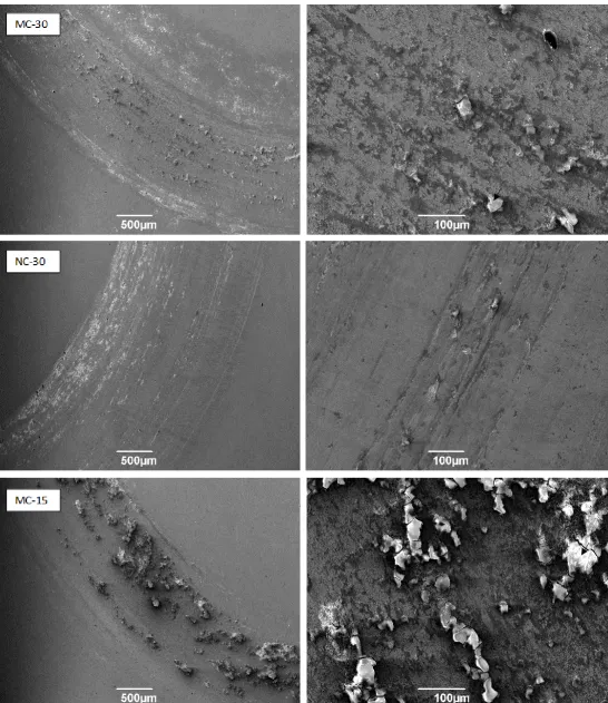
To gain an understanding of the wear mechanisms taking place, the plan view of the wear
tracks was analysed using SEM. Figure 7 shows the worn surfaces of the three coatings
tested at the 96 N load. Sections of material can be seen appearing to crack and break off
from the coating surface in the MC-30 and MC-15 coatings and at higher magnification, it
can be observed that these sections breaking off consist of a different phase, this is labelled
in Figure 7 with an arrow. EDX analysis showed that the composition of this phase consists
primarily of tungsten and oxygen (W = 64.65 % wt, O = 26.40% wt) suggesting that this
phase is an oxidised particle formed due to the work done on the coating surface by the
counterbody being converted to heat energy, resulting in localised higher temperatures on
the coating surface and therefore increasing the oxidation rate (tribo-oxidation). However this
phase was found to form much less significantly on the NC-30 coating when tested at 96 N
which may explain the lower specific wear rate recorded. On this coating, the primary source
of wear appears to be from scratches running in the direction of counterbody movement,
suggesting ploughing has taken place with the abrasive body probably consisting of WC
particles, as these would have sufficient hardness to cause abrasion on the soft binder
phase. Areas in which pullout of the carbide grains can be detected, suggesting that these
abrasive particles probably originated from the coating surface.
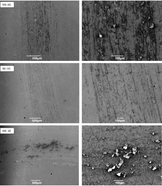
Figure 8 shows the worn coating surfaces when the load is increased to 168 N; on all three
observed in particular on the MC-15 coating, which was measured to have the highest
specific wear rate at this particular load suggesting that the formation of this layer of oxidised
particles has a significant impact on the measured specific wear rate. Signs of abrasive wear
can be observed particularly on the MC-30 and NC-30 coatings in the form of scratches in
the direction of the counterbody movement, probably the result of a similar abrasion
mechanism occurring with WC particles acting as the hard phase, as is previously described
above for the NC-30 coating at 96 N.
The worn surfaces of the coatings tested at 240 N are displayed in Figure 9. The formation
of the cracked oxidised particles is observed on all three coatings, especially again on the
MC-30 and MC-15 coatings. It can be seen that the width of the wear track is larger on the
NC-30 coating in comparison to the other two coatings which may explain why this coating
had the highest measured specific wear rate.
4 Discussion
4.1 Coating microstructure and mechanical properties
All three powders suffer from some degree of decarburisation when being sprayed with this
HVOAF spray system at the selected spray parameters, which is the expected result when
comparing this data to previous work as WC cermet powders have been shown to suffer
carbon loss when exposed to the high temperatures present in the HVOF process [18, 19].
In particular the finer powder MC-15 was found to decarburize more significantly than the
other powders; this is probably due to the higher temperatures reached by the smaller
powder particles during spraying when compared to the other powders, resulting in
increased WC dissolution in the metallic binder.
In contrast to other findings [20], it was found that the nanostructured powder NC-30
decarburized at a similar rate to the larger WC grain MC-30 powder. It is previously
described that when following the established mechanism for the carbon loss in WC cermet
to the increased surface area to volume ratio of the smaller WC grains leading to higher
dissolution of these grains in the binder phase during spraying. This effect however may
have been counteracted by the fact that the MC-30 powder particles appear to possess a
less compact morphology than the NC-30 powders, meaning that the actual surface area
may be lower on the nanostructured powder. A reduced surface area results in a smaller
heat transfer area, reducing decarburisation and therefore possibly explaining why these two
powders were similar in terms of decarburisation. However as the surface area of the
particles was not explicitly measured, this cannot be verified for certain.
The results of the current study indicate that powder particle size has a much larger effect on
decarburisation than carbide size, suggesting that particle temperature is the most important
factor affecting carbon loss when applying these coatings using this spray system. This
could be due to two possible factors; the heightened decarburisation at increased particle
temperatures may be due to increased solubility of the liquid binder or increased liquid
fraction of the binder phase at the higher temperature leading to greater dissolution of the
WC grains. It is possible that carrying out further spray parameter optimisation work to
suppress the melting of the metallic binder phase could inhibit the dissolution of the WC
phase, meaning that the performance of the coatings in this study could be improved further
in time.
Previous researchers have stated that nanostructured WC-Co-Cr powder feedstocks result
in coatings with a much higher hardness; their reasoning being that reducing the carbide
size results in increased hardness and fracture toughness due to the Hall-Petch effect [7].
This is because decreasing the carbide grain size and binder mean free path results in
increased suppression of dislocation propagation and this jamming of slip therefore means
fracture toughness is increased [21]. However the results of this study may differ from these
statements, with the nanostructured coating NC-30 being shown to possibly have a slightly
It was determined that the MC-30 and MC-15 coatings had a similar microhardness level.
Previous studies carried out using this spray system determined that higher in-flight particle
velocities result in greater cold hardening effects, due to the increased peening effect on the
substrate [11]. This effect may lead to resulting increased compressive residual stresses in
the MC-15 coating when compared to MC-30, leading to an overall increase in
microhardness. This hardening effect however is counteracted in the MC-15 coating by the
increased level of WC dissolution taking place, meaning the resulting microhardness of the
two coatings is at a similar level.
Another possible factor affecting the microhardness and fracture toughness of the three
coatings is the amount of W2C present in the coating microstructure. It has been previously
shown that the microhardness of cast WC and W2C are 17000 MPa and 30000 MPa
respectively [22], suggesting that the formation of W2C due to decarburisation could result in
an increase in coating microhardness. This result has also been suggested in a number of
other studies [23, 24]. However, the elevated presence of W2C may also reduce the fracture
toughness of the coating, with the fracture toughness of WC and W2C being measured at 5.9
MPa.m1/2 and 3.6 MPa.m1/2 respectively [25]. The results in this study appear to agree with
this hypothesis in particular when studying the MC-30 and MC-15 coatings, as the reduced
fracture toughness of the MC-15 coating could be explained by the increased presence of
W2C.
Increased porosity has been shown to reduce the microhardness of coatings [26] and as the
measured porosity was higher in the MC-30 coating than the MC-15 coating, this may also
have an effect. The nanostructured coating displayed a lower amount of W2C than the
MC-15 coating, but had reduced microhardness and fracture toughness suggesting that reducing
the WC grain size has an overall negative effect on the coating’s mechanical properties
when spraying using the novel HVOAF torch utilised in this study.
Powder particle size has also been shown to affect coating porosity, as the percentage
indicate that the in flight velocity of the particles when spraying the MC-15 powder is higher
than the others, as it has been shown previously that reaching a greater particle velocity
during spraying leads to reduced porosity in the final coating [5]. In addition, it has also been
shown that coating porosity is reduced as coating thickness is increased [27], meaning that
the reduced porosity could be due to the higher thickness of the NC-30 coating.
4.2 Wear Behaviour
Past studies have often concluded that decarburisation of WC cermet coatings has a
negative effect on the sliding wear resistance of the coatings as the presence of hard but
brittle W2C has been said to reduce toughness and increase wear [28].
At 96N the nanostructured coating performed best, showing wear rates significantly lower
than the other two coatings. Meanwhile at this load and at 168 N the MC-15 coating, which
was found to have suffered the most carbon loss (Fig 2), displayed the highest specific wear
rates seemingly in agreement with the above statement (Fig 6). However, as the load was
increased to 240 N this coating was found to perform similar to previous two loads but better
than the nanostructured coating. This suggests that the inferior microhardness and fracture
toughness of the NC-30 coating resulted in it suffering more under the higher load in
comparison to the other two coatings, making it the suffer the highest amount of wear at 240
N.
The width of the wear track was shown to be significantly larger on the NC-30 coating when
tested at 240N, in comparison to the other two samples tested, meaning that although the
normal force exerted on each coating is equal, the pressure is not. This effect could explain
the reduced number of oxidised particles on the surface of the wear track for the NC-30
coating at 240N, as the normal force is exerted onto a larger area due to the wider wear
track, meaning that the frictional forces are less concentrated, meaning less tribo-oxidation
As the trend of the NC-30 coating wear differs greatly from the other two larger WC grained
coatings, it is likely that a different mechanism of wear is taking place with this coating. At
the 96 N load, the oxidised particles that can be observed on the surface of the wear tracks
on the MC-30 and MC-15 coatings in Figure 7 did not form nearly as significantly on the
NC-30 coating. This could possibly indicate lower frictional forces and therefore less heat energy
available for the film formation to take place and this could explain why the nanostructured
coating performed better than the others at 96 N, making this coating possibly more suitable
than the others for applications where protection from smaller loads is required. However the
inferior microhardness and fracture toughness of this coating may have been the reason for
the worse performance of this coating at the 240 N load.
4.3 Future application of a WC-Co-Cr coating for internal surfaces
When coating internal diameters, the local environment in which the spray torch is operating
is very different; the stand-off distance will likely be shorter which can lead to higher coating
porosity and lower density. The dissipation of heat may be reduced when coating an internal
surface, meaning that substrate temperatures will increase further resulting in the greater
oxidation of the splats post impact. Due to these effects along with others, it cannot be
predicted exactly how these coatings would perform if sprayed internally, although the data
in this study indicates that the new HVOAF spray system used in this study is capable of
spraying WC-Co-Cr coatings in line with other commercially used systems in terms of
mechanical properties, so results are promising. The effects of spraying internally will be
covered in future work.
In this study, it was shown that using the nanostructured powder did not increase
microhardness as expected and due to having the worst mechanical properties of the three
materials tested, the NC-30 coating will not be taken forward for future internal spray trials.
The results of this study show that while the MC-15 powder may be suitable for internal
conventional MC-30 powder in terms of the wear resistance and mechanical properties, the
smaller powder particle size makes this material much more sensitive to temperature effects.
These have been shown to impact the coating’s microstructure and mechanical properties
however when considering the shorter stand-off distances often seen in internal diameter
HVOF, this may be less of a significant issue
5 Conclusion
Three WC-10%Co-4%Cr based powders with varying powder particle size range and carbide
grain sizes were deposited using an HVOAF system developed by Castolin Eutectic-Monitor
Coatings Ltd. (UK). The microstructure of the powders and coatings were examined by SEM
and XRD, followed by performance testing of the coatings by unlubricated sliding wear testing.
From the results of this study the following conclusions can be made:
Characterisation of the powder and coating microstructures using SEM and XRD
revealed that the MC-15 powder decarburised during spraying to a greater extent
compared to the MC-30 and NC-30 powders, possibly due to the finer powder reaching
a higher temperature during spraying.
The MC-15 and MC-30 coatings were found to have a similar microhardness, with the
nanostructured coating possessing the lowest measured microhardness and fracture
toughness. The reduction in fracture toughness may also be attributed to the relatively
higher decarburisation compared to MC-30 and NC-30.
In the sliding wear testing at 96 N the nanostructured coating performed best, making
it the most suitable for low load applications. Oxidised particles that were observed on
the surface of the MC-30 and MC-15 coatings at 96 N were not seen in the
nanostructured coating, suggesting the formation of these oxidised particles is a key
factor in the wear mechanism taking place. However, at 240 N this coating displayed
the highest specific wear rates with the possible reason being its inferior
outperformed it by a similar degree; therefore, a medium carbide coatings should be
chosen for higher load applications based on this data.
For the development of a WC-Co-Cr coating for an internal spray application, the finer
powder MC-15 is probably the most suitable due to the fact that the smaller size of this
powder is a considerable advantage when spraying internally due to the lower kinetic
energy required alongside comparable performance to the conventional MC-30
powder in terms of the wear resistance and mechanical properties. However, the
smaller size of the powder leads to it being much more sensitive to temperature
changes, meaning spray parameter optimisation may be vital to reduce
decarburisation. Following the results of this study, the spray parameters used when
applying coatings of the MC-15 powder with this ID HVOAF torch have been optimised
further, with much lower decarburisation and higher microhardness and fracture
toughness being achieved.
Acknowledgement
This work was supported by the Engineering and Physical Sciences Research Council
[EP/L016362/1]; in the form of an EngD studentship and industrial funding from Castolin
Eutectic- Monitor Coatings Ltd.
References
1 M. Bielewski, Replacing Cadmium and Chromium, the Research and Technology Organisation and NATO, AG-AVT-140 (2011), Chp. 23, p 1/22
2 K. Legg and C. Pellerin, SERDP/ESTCP Metal Finishing Workshop Summary, SERDP & ESTCP Program Office, Washington,
3 Lyphout, C. and S. Björklund. "Internal Diameter HVAF Spraying For Wear And Corrosion Applications". Journal of Thermal Spray Technology (2014)
4 Bolelli G, Berger L, Börner T, Koivuluoto H, Lusvarghi L, Lyphout C et al. Tribology of HVOF- and HVAF-sprayed WC–10Co4Cr hardmetal coatings: A comparative
assessment. Surface and Coatings Technology. 2015;265:125-144.
5 Zhao, L., Maurer, M., Fischer, F., Dicks, R. and Lugscheider, E. (2004). Influence of spray parameters on the particle in-flight properties and the properties of HVOF coating of WC-CoCr. Wear, 257(1-2), pp.41-46
7 Thakur L, Arora N. Sliding and Abrasive Wear Behavior of WC-CoCr Coatings with Different Carbide Sizes. Journal of Materials Engineering and Performance.
2012;22(2):574-583
8 Kear, B., Skandan, G., & Sadangi, R. (2001). Factors controlling decarburization in HVOF sprayed nano-WC/Co hardcoatings. Scripta Materialia, 44(8-9), 1703-1707. 9 Schwetzke, R. and Kreye, H. (1999). Microstructure and Properties of Tungsten
Carbide Coatings Sprayed with Various High-Velocity Oxygen Fuel Spray Systems. Journal of Thermal Spray Technology, 8(3), pp.433-439
10 Allcock, B., Gu, S. and Kamnis, S. (2013). Nozzle for a Thermal Spray Gun and Method of Thermal Spraying. EP2411554A1
11
Katranidis V, Gu S, Allcock B, Kamnis S. Experimental study of high velocity oxy-fuel sprayed WC-17Co coatings applied on complex geometries. Part A: Influence of kinematic spray parameters on thickness, porosity, residual stresses andmicrohardness. Surface and Coatings Technology. 2017; 311:206-215.
12 Sudaprasert, T. (2002). An Investigation of Microstructure and Sliding Wear in Thermally Sprayed WC-Co Coatings. Ph.D. The University of Nottingham
13 Shipway, P., McCartney, D. and Sudaprasert, T. (2005). Sliding wear behaviour of conventional and nanostructured HVOF sprayed WC–Co coatings. Wear, 259(7-12), pp.820-827
14 Sudaprasert, T., Shipway, P. and McCartney, D. (2003). Sliding wear behaviour of HVOF sprayed WC–Co coatings deposited with both gas-fuelled and liquid-fuelled systems. Wear, 255(7-12), pp.943-949
15 Shipway, P. (1999). The role of test conditions on the microabrasive wear behaviour of soda-lime glass. Wear, 233-235, pp.191-199.
16 Evans, A. G., and To R. Wilshaw. "Quasi-static solid particle damage in brittle solids—I. Observations analysis and implications." Acta Metallurgica 24.10 (1976): 939-956.
17 Picas J, Rupérez E, Punset M, Forn A. Influence of HVOF spraying parameters on the corrosion resistance of WC–CoCr coatings in strong acidic environment. Surface and Coatings Technology. 2013;225:47-57
18 Jacobs, L., Hyland, M. and De Bonte, M. (1998). Comparative Study of WC-Cermet Coatings Sprayed via the HVOF and the HVAF Process. Journal of Thermal Spray Technology, 7(2), pp.213-218.
19 Gong, T., Yao, P., Zuo, X., Zhang, Z., Xiao, Y., Zhao, L., Zhou, H., Deng, M., Wang, Q. and Zhong, A. (2016). Influence of WC carbide particle size on the microstructure and abrasive wear behavior of WC–10Co–4Cr coatings for aircraft landing
gear. Wear, 362-363, pp.135-145.
20 Stewart, D., Shipway, P. and McCartney, D. (1999). Abrasive wear behaviour of conventional and nanocomposite HVOF-sprayed WC–Co coatings. Wear, 225-229, pp.789-798.
21 K. Jia and T.E. Fischer, Sliding Wear of Conventional and Nanostructured Cemented Carbides, Wear, 1997, 203–204, p 310–318
22 Zakharova E, Markova I, Maslov A, Polushin N, Laptev A. Morphology of powders of tungsten carbide used in wear-resistant coatings and deposition on the PDC drill bits. Journal of Physics: Conference Series. 2017; 857:012058.
24 Jacobs L, Hyland M, De Bonte M. Study of the Influence of Microstructural Properties on the Sliding-Wear Behavior of HVOF and HVAF Sprayed WC-Cermet Coatings. Journal of Thermal Spray Technology. 1999;8(1):125-132.
25 Taimatsu H, Sugiyama S, Kodaira Y. Synthesis of W2C by Reactive Hot Pressing and Its Mechanical Properties. Materials Transactions. 2008;49(6), pp.1256-1261. 26 Davis, J. (2004). Handbook of thermal spray technology. Materials Park, OH: ASM
International
27 Bolelli, G., Lusvarghi, L. and Barletta, M. (2009). HVOF-sprayed WC–CoCr coatings on Al alloy: Effect of the coating thickness on the tribological properties. Wear, 267(5-8), pp.944-953
Figure 3 – Left: Low magnification SE SEM images of coating cross section. Right: BSE SEM images of coating cross section microstructure Example areas of W heavy binder are labelled with arrows. Areas with a black contrast were found to not be porosity, but a Cr rich phase
MC-30
NC-30
Table 2 - Summary of coating properties
Sample Name
Coating Thickness (µm)
Microhardness (HV0.3)
Fracture Toughness Kc
(MPa.m0.5)
Porosity (%)
Index of Carbon Retention
MC-30 317 1313 ± 60 4.00 ± 0.36 0.53 ± 0.24 0.86
NC-30 512 1246 ± 58 3.62 ± 0.65 0.34 ± 0.15 0.85
MC-15 290 1341 ± 43 3.89 ± 0.52 0.27 ± 0.11 0.67
[image:25.595.74.524.267.582.2]Figure 5- Specific Wear Rates of the NC-30 coating at 96 N, 168 N and 240 N with the associated counterbody wear
[image:26.595.74.525.436.738.2]