A Centering Correction Method for GNSS
Antenna Diversity Theory and Implementation
using a Software Receiver
Peng Zhang1,3, Fuyu Sun1, Yaming Xu1, Jingui Zou1, Wujiao Dai2,3, Xiaolin Meng3,
1 School of Geodesy and Geomatics, Wuhan University, China
2 Department of Surveying Engineering & Geo-informatics, Central South University, China 3 Nottingham Geospatial Institute, University of Nottingham, UK
BIOGRAPHY
Peng Zhang is a lecture in School of Geodesy and Geomatics, Wuhan University, China. He holds a Ph.D. degree in Electronic and Information Engineering from Huazhong University of Science and Technology. From March 2013, he has been working at the Nottingham Geospatial Institute of the University of Nottingham as a academic visitor. His main research interests are signal processing in software GNSS receiver, and wireless sensor networks.
Fuyu Sun is a PhD candidate in School of Geodesy and Geomatics, Wuhan University, China. He got MSc degree in Geomatics Engineering from the same University in 2010. His main research interest is signal processing in software GNSS receiver.
Yaming Xu is a professor in School of Geodesy and Geomatics, Wuhan University, China. He holds a Ph.D. degree in Geomatics Engineering from Wuhan University. His research interests include precise engineering surveying, industrial measurement, and multi-sensor integration.
Jingui Zou is a professor in School of Geodesy and Geomatics, Wuhan University, China. He holds a Ph.D. degree in Geomatics Engineering from Wuhan University. His research interests are engineering surveying, and structural health monitoring.
Wujiao Dai is an associate professor in Department of Surveying Engineering & Geo-informatics in Central South University, China. He got his Ph.D. degree in 2007. He has been a research assistant in HongKong Polytechnical University for 3 years. His research interests focus on deformation monitoring using GNSS and deformation analysis.
Xiaolin Meng is an associate professor in Nottingham Spatial Institute, University of Nottingham. He holds Ph.D. degrees from Tongji University in China (1998) and University of Nottingham (2002). His current
research focus on ubiquitous positioning, location based services, intelligent transportation systems and services, and precise point positioning. He is the author of more than 200 papers and a regular speaker in the key international conferences and symposiums. He is chair of sub-commissions within a few international associations.
ABSTRACT
GPS is performing well in open sky situation. However, severe attenuation or blockage of signals by high buildings may leads to an insufficient number of received satellites. Antenna diversity scheme is viewed as a method to alleviate signal attenuation and enhance the performance of GNSS positioning in the harsh environments. This paper introduces an antenna diversity system, composed of two spatially separated antennas. If relative geometry of two antennas is known, the carrier phase measurement outputs from these two antennas can be combined with Centering Correction Method (CCM). Even each antenna may not able to acquire more than four satellites this antenna diversity system can still precisely estimate each antenna’s location with centimeter-level accuracy, as long as the sum of the captured satellites by two separate antennas is no less than four.
INTRODUCTION
regarded as an effective method for decreasing the value of DOP, but the buildings and other obstacles, such as buses and trees, can still severely attenuate or even block the signals from multi-constellation GNSS satellites. Another approach to mitigate severe signal attenuation is taking advantage of diversity schemes. Diversity scheme is regarded as a method to alleviate signal attenuation and to enhance signal detection and parameter estimation performance by providing additional spatial processing gain. As [1] demonstrates, multiple antennas in a form of an antenna diversity system can diminish signal attenuation by combining independent signals from each individual antenna.
However, in urban canyon environment, acquiring more than four satellites at any time is uneasy to realize for GPS receivers. This kind of scenario cannot be solved with the traditional diversity method as proposed in [1]. Although reference [2] represents a novel collaborative method between separate receivers, it still cannot handle the scenario when less than four satellites can be captured by each receiver. In our previous work, we had implemented an antenna diversity system with a software receiver, utilizing Universal Software Radio Peripheral (USRP) as the frond end [3]. Benefiting from flexibility of a software receiver, the pseudorange observations of two antennas can be flexibly combined, which can be understood as one single “virtual antenna”. Even each satellite can not detect more than four satellites, this diversity system may still obtain the location of the “virtual antenna”, as long as the sum of captured satellites by two separate antennas is no less than four.
This paper can be regarded as extension of our previous work in [3] with two enhancements. First, since carrier phase measurements are generally considered to be the most precise measurements [4], carrier phase measurements from separated antennas are deliberately combined; Second, we assume that relative geometry of two antennas is known, which actually can be easily obtained by pre-surveying in reality. As the distance between two antennas is much smaller than the range from an antenna to a satellite, the line-of-sight vectors from two antennas to a given satellite can be treated as parallel. Even if one of the vectors may be blocked by obstacles, this non-line-of-sight vector can still get recovered by trigonometric correction, which is the key idea of CCM. Eventually, with the approach proposed in this paper, a more accurate positioning result can be achieved.
Beam steering is another effective method for mitigating GNSS signal attenuation by effectively processing signals from multiple antennas [5], which seems similar to this CCM. Nevertheless, since beam steering method works at a signal level, every sample will be processed in turn, causing enormous calculation burden. Comparatively speaking, CCM works at a measurement level, i.e., the correction process only happening at each epoch, which reduce computation load. Again, beam steering method
still cannot handle the scenarios with insufficient satellites effectively.
The remainder of the paper is organized as follows. In Section II, signal models are briefly reviewed. Then, CCM is illuminated in Section III. Data collection and results analysis are included in Section IV. Section V concludes the paper and introduces the future work.
SIGNAL MODELS
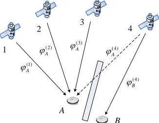
Carrier phase measurement is a measure of the range between a satellite and a receiver expressed in a unit of cycles of the carrier frequency. To measure the carrier phase in GPS, a receiver acquires phase lock with the satellite signal, measures the initial fractional phase difference between the received and replica signals, and from then on tracks the changes in this measurement through counting full cycles and keeping track of the fractional cycle [4]. Precise carrier phase measurement provides important guarantee for high accurate positioning, which is also vulnerable to all kind of signal interferences. It is a challenging task for a receiver to output consecutive and stable carrier phase measurements. In urban canyons, due to the severe attenuation or blockage of satellite signals by high buildings, each GPS antenna can not keep locking the signals from more than four satellites for sometime, which means the receiver can not output carrier phase measurements as well. In consequence, the location of the antenna can not be obtained. Figure 1 demonstrates such a scenario.
(4)
B
(4)
A
A
B 1
2 3 4
(1)
A
(2)
A
[image:2.612.361.524.418.544.2] (3)A
Figure 1: Typical scenario with severely blocked signals
position. The X axis is the east direction, Y axis is the north direction and Z axis is up direction. We use boldface characters to denote vectors. For example in this figure ddenotes the baseline vector of antenna B. The distance and angle of baseline vector d are indicated bydand. Sincedis much smaller than the range from an antenna to the satellite 4, the line-of-sight vectors from two antennas to the satellite may be treated as parallel. This common unit vector to the given satellite is indicated bye.
d
X
Y Z
A
B
A
B
e
[image:3.612.80.267.182.305.2]4
Figure 2: Geometry of satellite and antennas
The key idea of the CCM is to intelligently combine information of the two antennas for achieving more accurate positioning results. The following discussion describes how the CCM works.
CENTERING CORRECTION METHOD
As mentioned, only antennaBcan keep tracking signal from satellite 4. Accordingly, the satellite signal at antennaBcan be represented as:
( ) ( ) ( ) cos 2 ( )
B c B B
s t C t D t f f t (1)
whereC t( ) and D t( ) denotes C/A code and navigation
message respectively for the satellite, fc is the signal
down-conversion frequency, fB is the instantaneous value of the Doppler frequency shift of the received satellite signal at antennaB. B represents instantaneous carrier phase of the satellite signal at antennaB.
We can also use the signal as virtual one at antennaA, even this signal does not exist in reality due to the impact of blockage,
( ) ( ) ( ) cos 2 ( )
A c A A
s t C t D t f f t (2)
where fA and A are the instantaneous value of the Doppler frequency shift and carrier phase of the received satellite signal at antennaA, respectively.
Equations (1) and (2) indicate that, for certain satellites, two main differences between the signals received by antennaAandB are the instantaneous value of Doppler frequency shift ( fAand fB ) and instantaneous carrier
phase (A and B). Because Doppler frequency shift only concern with signal wavelength and the line-of-sight component of the transmitter-receiver relative velocity vector, fA and fB can be regarded as approximately equal due to the spatial proximity of two antennas. Then, the main difference between signals at antenna A and B
is instantaneous carrier phase measurements, A and B.
In the following, we will demonstrate that, although A does not exist, we can still estimate its value based on the measured value of B and the geometry relationship among the satellite and two antennas. This can be understood as: with the help from antenna B , antenna A can also “observe” the satellite signal and
output carrier phase measurement correspondingly. In Figure 2, since the line-of-sight vectors from two antennas to the given satellite may be treated as parallel,
B
can be approximated as the sum of A and as shown in Equation (3). is the correction value to be calculated.
A B
(3)
In addition, the elevation angle and azimuth angle of satellite 4 can be indicated by and . It is worth mentioning that since the approximate locations of these two antennas can be achieved by the method in [3], and the accurate location of the satellite can be extracted from navigation message, the elevation angle and azimuth angle of satellite can be acquired in real time. Application of straightforward trigonometric relationships allows us to determine the value of correction with Equation (4), whereis signal wavelength of satellite signal.
cos sin
d
(4)
As long as the value of is obtained, A can be achieved according to Equation (3).
The whole procedure of CCM can be summarized as follows:
1) Get relative geometry of two antennas by pre-surveying and the approximate positions of antenna
Aand Bcan be estimated based on the method in [3]. The work in this step can be finished in advance.
3) At each epoch, correction value can be calculated with equation (4). Although in our assumption, antenna
Acan not detect signal from satellite 4, the carrier phase measurement calculated with Equation (3) can still be regarded the real output from antennaA, just as antenna
Aoutput carrier phase measurement by itself.
4) Carrier phase measurements from satellite 1, 2, 3 and 4 can be utilized to estimate antennaA’s accurate
location. Since this CCM only happens at each epoch, the calculating burden is acceptable.
In this scenario, antennaAcan be treated as a “center”
and corrected carrier phase measurement from antenna
Bcan be regarded as a serving role for the “center”. That
is why this method is named centering correction.
DATA COLLECTION AND RESULT ANALYSIS
In this part, we choose to evaluate the performance of CCM upon a software receiver platform. The rapid advancement in a software defined radio technology has made software receivers more flexible and less costly. Key benefits of a software receiver platform are its flexibility and configurability, which is particularly suitable for this test. Universal Software Radio Peripheral (USRP) is a dedicated front-end, which is intended to be a comparatively inexpensive hardware platform for software radio. With appropriate daughterboard configurations, USRP has the potential to capture the entire GNSS family of signals. In this test, two DBSRX daughterboards are assembled inside one USRP, and each DBSRX daughterboard can be used to connect with one antenna. DBSRX daughterboard can handle signals from 800 MHz to 2.4 GHz. Because these two DBSRX daughterboards share the reference oscillator in USRP, they experienced the same clock drift. Hence, the synchronization between them needs not to be deliberately concerned in this research.
To achieve more accurate coordinates of positions, static surveying and double-difference technique are demanded. Static surveying technique, utilizing data from multiple epochs, may consume more time, with the benefit of higher accuracy. Double-difference technique is an effective way to eliminate common-mode errors, such as satellite clock error, ionospheric and tropospheric delays, and in addition receiver’s clock bias. LGO from Leica was utilized to calculate locations and output static surveying result based on the multiple epoch outputs from USRP.
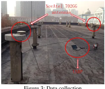
A field test was implemented on the roof of School of Geodesy and Geomatics, Wuhan University, China. As shown in Figure 3, two NovAtel 702GG antennas, fixed on two observing pillars, were connected with one USRP. Two antennas’ precise coordinates were carefully calibrated in advance. Only with their help, would it be possible to judge the performance of CCM. The USRP takes charge of transforming high frequency radio signals to low frequency intermediate signals and digitizing
analog intermediate signals into discrete samples. All the other proceedings are finished in computer, connected with USRP by USB interface.
NovAtel 702GG antennas
[image:4.612.350.531.99.253.2]USRP
Figure 3: Data collection
This experiment began at 12:45 and ended at 15:10 on Dec 23, 2013. Figure 4 depicts the real sky plot during field test. And Figure 5 shows the satellites’ visible time. Almost half of satellites are at low elevation angles.
[image:4.612.327.552.461.561.2]Figure 4: Skyplot during field test
Figure 5: Satellites’ visible time during field test
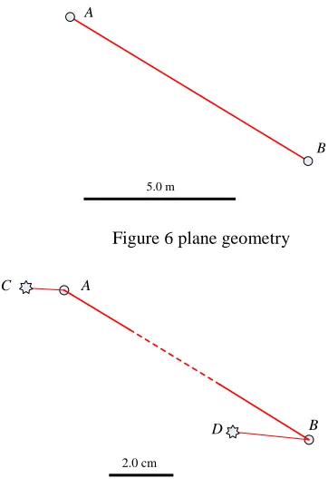
antennaB. Then, both antennas could have consecutive carrier phase measurements from five satellites. Eventually, accurate positioning results can be achieved. Figure 6 outlines the plane geometry relationship between antenna AandB. The precise distance between them is 9.245m, where plotting scale in Figure 6 is 5.0 meters.
B A
[image:5.612.60.241.125.394.2]5.0 m
Figure 6 plane geometry
A C
2.0 cm
B D
Figure 7 Positioning results
Figure 7 depicts calculated locations for antenna A and
B by CCM. For clarity, these calculated locations are indicated byC and D respectively, for distinguishing from their real locations. In addition, the plotting scale in Figure 7 is 2.0 centimeters. As expected, both location biases for antenna A and antenna B are less than 2 centimeters, which can meet the demands from most applications.
In general, when static surveying and double differences are implemented, sub-centimeter positioning accuracy can be achieved by this USRP platform. We believe that centimeter bias in this test is mainly induced by the approximate positions for two antennas. This approximation can bring extra errors in the following trigonometric calculation. Something needs to be further studies.
CONCLUSION AND THE FUTURE WORKS
This paper presented a centering correction method (CCM) for GPS antenna diversity system. With known relative geometry relationship between two separated antennas, carrier phase measurements from these two antennas can be combined with flexibility by CCM. Field test was performed to evaluate the effectiveness of this method. Even less than four satellites could be acquired by each
antenna, the positions for both antennas can still be achieved with centimeter-level accuracy. We believe that CCM do have the potential to increase the options one has to solve a particular accurate positioning problem. Although our research focuses on GPS, this CCM can also be applied for other GNSS systems as well.
There are a number of issues that are worthy of continued studies. First, suitable synchronizing algorithm between separated antennas should be deliberately considered although the synchronization problem does not to be concerned in this research due to the fact that two antennas sharing the common clock. Second, more separated antennas with known spatial geometry relationship can further improve system performance but also incur complexity. We will analyze this tradeoff problem in the future work. Third, more realistic scenarios deserve to be involved to evaluate real time performance of CCM.
ACKNOWLEDGMENTS
The research is supported by Doctoral Program of Higher Education of China (No. 20110141120046), Key Laboratory of Precise Engineering and Industry Surveying, National Administration of Surveying, Mapping and Geoinformation (No. PF2001-3), and National Natural Science Foundation of China (No. 41074025).
The author would like to thank China Scholarship Council to provide financial support for his academic visiting at Nottingham Geospatial Institute of the University of Nottingham. He also likes to thank Nottingham Geospatial Institute for offering him this academic visiting opportunity.
REFERENCES
[1] Seyed Nima Sadrieh, “Spatial Antenna Diversity Performance for Indoor GNSS Application,” Peoceeding of GNSS 2011, Portland OR, 20-23 Sep 2010.
[2] ANDREY SOLOVIEV, JEFFREY DICKMAN, JACOB CAMPBELL,MUSTER, “A Collaborative GNSS Receiver Architecture for Weak Signal Processing,” Inside GNSS, 56-68, May/June, 2013. [3] Peng Zhang, Fuyu Sun, Shuguo Pan, Xiaolin Meng,
“GPS Antenna Diversity Theory and Implementation with Software Receiver Platform,” 6th European Workshop on GNSS Signal and Signal
Processing, Neubiberg, 5-6 Dec 2013.
[4] Pratap Misra and Per Enge, Global Positioning System: Signals, Measurements, and Performance, Second Edition. Lincoln, MA :Ganga-Jamuna Press, 2011.