Application of Laser Removal Processing on Magnesium Alloy Anodized
from Phosphate Solution
Makoto Hino
1, Yutaka Mitooka
1, Koji Murakami
1, Katsuji Nishimoto
2and Teruto Kanadani
3 1Industrial Technology Research Institute of Okayama Prefecture, Okayama 701-1296, Japan2ARRK OKAYAMA CO. LTD., Maniwa 719-3143, Japan
3Faculty of Engineering, Okayama University of Science, Okayama 700-0005, Japan
Effects of the laser removal processing on corrosion resistance and conductivity for the magnesium alloy products anodized from the phosphate electrolytic solution were examined. The area where anodized coating was removed under the appropriate laser irradiated condition showed the excellent corrosion performance as well as good conductivity. This improvement of the conductivity is attributable to the removal of the anodized coatings whose conductivity is not good, and molten sputter then formed from the magnesium alloy substrate by means of the laser thermo processing becomes covered with the anodized coatings. Furthermore, this excellent corrosion resistance is based on the sacrifice corrosion protection by anodizing from the phosphate electrolytic solution. [doi:10.2320/matertrans.MC201005]
(Received November 24, 2010; Accepted February 21, 2011; Published April 20, 2011)
Keywords: magnesium alloy, laser removal processing, YVO4laser, corrosion performance, conductivity, anodic oxidation
1. Introduction
Magnesium alloy has been applied to the bodies of electronic equipment due to its excellent characteristics such as high rigidity, thinness, light weight, good heat dissipation, good damping capacity, good electro-magnetic shielding effectiveness, and good recycling.1) However,
magnesium has the lowest electrochemical potential of common commercial metals and is extremely prone to corrosion and it is necessary to apply surface treatment. When treating the surface of such magnesium bodies, some degree of conductivity is required to prevent charging of the electronic circuit. At the present time the low-resistant conversion treatment has widely been applied because of its conductivity.2) However, corrosion
resist-ance of the conversion treatment is by no means satisfac-tory for long life application. The conductive anodic oxidation coating was developed and applied for coating magnesium body frames for electric equipments,3) but it was difficult to improve both of conduction and corrosion resistance, since corrosion resistance and conduction are contradictory.
Magnesium alloy treated by anodizing from the phosphate electrolytic solution shows the excellent corrosion resist-ance,4)and this technology is currently applied on a massive
scale for coating magnesium products,5) however, it is not
possible to apply this to body frames for electronic equipment to form an insulation coating.
Recently, laser processing has been used for removing the oxide coating from aluminum alloy substrate as an advanced technology.6)
In this study, the removal of anodic oxidation coating from the phosphate electrolytic solution by the laser processing was tried for the purpose of improving both corrosion resistance and conductivity of magnesium alloy products. Furthermore, the mechanism of conductivity by the laser processing was examined.
2. Experimental Procedure
Experiments were conducted on AZ31B and AZ91D magnesium alloy plates shown in Tables 1 and 2, respec-tively. The specimens first underwent pretreatment by pickling and alkali cleaning. The electrolysis was carried out by using the phosphate electrolytic solution at 2985K.5) They were then subjected to constant current electrolysis anodizing. The average thickness of anodized layer was 10mm. For comparison, Dow17 anodizing7)with
an average thickness of 30mm and conversion treatment2)
were also used to prepare specimens.
Laser removal processing for the obtained coating was carried out using the YVO4 laser marker (MIYACHI
CORPORATION: ML-7112A). Laser processing conditions is shown in Table 3, and laser irradiation area is a square of 55mm2. After laser processing, the conductivity was
[image:1.595.302.550.363.389.2]evaluated using a resistivity meter (Lorester EP). The corrosion resistance was evaluated by anodic polarization (linear sweep voltammetry, LSV) using the electrochemical measuring system with potentiostat/galvanostat (Hokuto Denko HZ-3000) as well as a 5% NaCl spray test in accordance with ISO 9227 for 432 ks. To reveal the condition of coating with the laser processing, FE-SEM observations and FE-EPMA element mapping of the surface and cross-sections were carried out.
Table 1 Chemical composition of AZ31B magnesium alloy (mass%).
Alloy Al Mn Zn Fe Si Cu Ni Mg
AZ31B 2.87 0.38 0.85 0.003 0.014 0.0004 0.0003 bal.
Table 2 Chemical composition of AZ91D magnesium alloy (mass%).
Alloy Al Mn Zn Fe Si Cu Ni Mg
AZ91D 9.1 0.28 0.75 0.003 0.05 0.025 0.001 bal. Special Issue on Platform Science and Technology for Advanced Magnesium Alloys, V
[image:1.595.303.551.425.453.2]3. Results and Discussion
3.1 Laser removal processing for anodic oxidation coating and conductivity
[image:2.595.313.540.74.243.2]Figure 1 shows the appearance of laser irradiation for AZ91D magnesium alloy anodized from the phosphate solution. The white light emission was confirmed at the laser irradiated point on each specimen. However, the rise in the temperature of each specimen was slight after laser irradi-ation. There was no difference of this appearance during laser irradiation, depending on the kind of surface treatment.
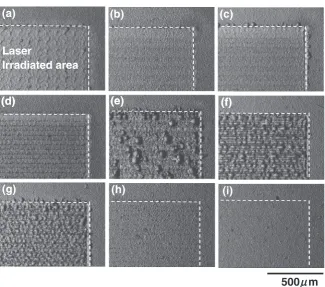
Figure 2 shows the backscattered electron images of the surfaces of the anodic oxidation coating from the phosphate
solution after the laser processing changed the oscillating frequency. Anodic oxidation coatings were removed from the AZ31B substrates by laser processing under the condition of the oscillating frequency from 1 to 10 kHz, however, a part of these coatings began to remain, as the oscillating frequency increased. Furthermore, solidification blobs were formed under the laser condition of the oscillating frequency from 50 to 100 kHz. Finally the change of the anodized surface rarely appeared under the condition of the oscillating frequency over 150 kHz.
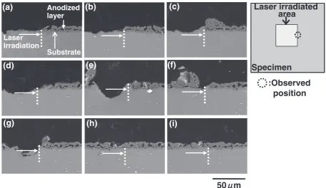
Figures 3 and 4 show the backscattered electron images of the cross-sectional anodized layers at the laser irradiated boundary and the center in the processing area, respectively. Anodic oxidation coatings were removed from the AZ31B
Table 3 Laser processing conditions.
Wavelength 1064 nm
Focusing distance 130 mm
Spot diameter 60mm
Defocusing distance 0 mm
Irradiation angle 0
Current 24 A
Oscillating frequency 1, 5, 10, 25, 50, 75, 100, 150, 200 kHz
Scanning speed 100 mm/s
Pitch interval 50mm
Fig. 1 Appearance of laser irradiation for anodized AZ91D magnesium alloy from the phosphate solution.
(a)
L
(b)
(c)
Laser
Irradiated area
(d)
(e)
(f)
(d)
(e)
(f)
(h)
(i)
(g)
500
μμ
m
[image:2.595.48.292.83.220.2] [image:2.595.135.461.288.575.2]substrates under the condition of the oscillating frequency from 1 to 5 kHz. At the laser condition of the oscillating frequency from 10 to 50 kHz, the AZ31B substrates were partially removed, and the solidification blobs were formed at the laser irradiated boundary. A part of these coatings began to remain over 75 kHz, and, finally, little change of the anodic oxidation coatings appeared under the condition of
oscillat-ing frequencies over 150 kHz. Results of the cross-sectional observation are in good agreement with the surface obser-vation.
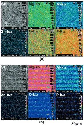
Figure 5 shows the secondary electron images and X-ray maps with magnesium, aluminum, zinc, phosphorus, and oxygen by FE-EPMA analysis for anodized specimen surface before and after laser irradiation. The elements of
magne-(a)
Anodized layer(b)
(c)
Laser irradiated
area
Laser Irradiation
Substrate
(d)
(e)
(f)
Specimen
:Observed
position
(g)
(h)
(i)
50
μμ
m
Fig. 3 Backscattered electron images of the cross-sectional AZ31B anodized layer at the laser irradiated boundary after laser processing. (a) 1 kHz, (b) 5 kHz, (c) 10 kHz, (d) 25 kHz, (e) 50 kHz, (f) 75 kHz, (g) 100 kHz, (h) 150 kHz and (i) 200 kHz.
(a)
(b)
(c)
Laser irradiated
area
Substrate
(d)
(e)
(f)
Solidification
Specimen
:Observed
position
(g)
(h)
Anodized(i)
layer blobs
Solidification blobs
Solidification blobs
50
Solidification
μμ
m
[image:3.595.68.526.71.335.2] [image:3.595.70.526.390.655.2]sium, aluminum, phosphorus, and oxygen which originated from the anodic oxidation coatings were uniformly distribut-ed before laser irradiation. On the other hand, phosphorus and oxygen slightly remained on the substrate after laser irradiation. From the results of SEM observation shown in Figs. 2, 3, and 4, although anodic oxidation coatings were wholly removed by laser irradiated condition of the oscillat-ing frequency from 1 to 5 kHz, FE-EPMA analysis revealed that the part of an anodic oxidation coating slightly remained onto the substrate.
Figure 6 shows the relationship between the Laser diode (LD) input current and the laser output power in the processing point at each oscillating frequency of the YVO4
laser used in this study. Laser output power relatively increases with increasing LD input current. However, laser output power is changed by the oscillating frequency at same LD current, and laser output power then increases with increasing the oscillating frequency at same LD input current. Conversely, peak intensity per a shot decreases with
SEI
Mg-k
αα
Al-k
α
Zn-k
O-k
α
P-k
Zn k
α
P k
α
SEI
Mg-k
α
Al-k
α
(a)
g
Zn-k
α
O-k
α
P-k
α
50 m
μ
(b)
Fig. 5 Secondary electron images and X-ray maps for magnesium, aluminum, zinc, phosphorus, and oxygen by FE-EPMA analysis for anodized AZ31B specimen surface; (a) before and (b) after laser irradiation (5 kHz).
6 7 8
CW 50kHz 20kHz
4 5
20kHz 10kHz 5kHz
2 3
0 1
12 14 16 18 20 22 24 26
Laser output power /W
LD input current i /A
[image:4.595.150.446.68.511.2] [image:4.595.320.533.578.759.2]increasing the oscillating frequency at same LD input current. So the peak intensity per a shot for the oscillating frequency range from 1 to 10 kHz is high in comparison with that of the higher oscillating frequency. Therefore, as the anodic oxidation coatings are directly vaporized by means of the ablation processing, the removal of coatings becomes feasible. On the other hand, the processing mode varies from ablation process to thermal process, depending on an increase of oscillating frequency, because the peak intensity decreases with increasing the oscillating frequency. And the thermal process then should be also applied with the laser ablation at the oscillating frequency from 10 to 100 kHz, since the coatings and substrates melted and solidified. Under the condition of the oscillating frequency above 150 kHz, although the laser output power increased, the peak intensity was too low to change the coatings.
Table 4 shows the surface resistivity after laser irradiation under the various conditions. The surface where coatings, of course, were removed under the laser condition of the oscillating frequency from 1 to 5 kHz showed the conduc-tivity in the same value as an AZ31B substrate. However, in spite of the part of a coating remaining or formation of the solidification blobs under the laser condition from 50 to 100 kHz, conductivity cloud be obtained. The reason why the conductivity cloud be obtained in spite of the coating remaining is described hereafter.
3.2 Laser removal processing of anodic oxidation coat-ing and its corrosion performance
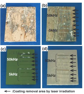
[image:5.595.47.551.86.123.2]Figure 7 shows the appearance of the laser irradiated surfaces for each specimen after salt spray test (SST) for 432 ks. AZ31B substrate without surface treatment intensely
Table 4 Surface resistivity of the anodized AZ31B magnesium alloy after laser irradiation under the various conditions.
AZ31B
substrate 1 KHz 5 KHz 10 KHz 25 KHz 50 KHz 100 KHz 150 KHz 200 KHz
1or less 1or less 1or less 1or less 1or less 1or less Over range Over range Over range
(a)
50kHz
(b)
5kHz
(c)
50kHz
(d)
50kHz
(c)
5kHz
5kHz
:Coating removal area by laser irradiation
[image:5.595.126.476.144.538.2]corroded in the full face (Fig. 7(a)). This result indicates that AZ31B magnesium alloy is extremely prone to corrosion. Corrosion resistance of the specimen treated by conversion treatment (Fig. 7(b)) was more excellent than that of the untreated AZ31B substrate, however, this specimen was also corroded in the full face. Dow17 anodized specimen (Fig. 7(c)) had an excellent corrosion resistance in compar-ison with the conversion treatment, however, this specimen in the area where a coating was removed by the laser irradiation, was intensely corroded. This corrosion is attrib-uted to the removal of the passive coating by the laser irradiation.
On the other hand, the anodized specimen from the phosphate solution (Fig. 7(d)) showed superior corrosion resistance in comparison with other surface treatments. In particular, it was noteworthy that corrosion was not occurred in the area where the coating was removed by the laser irradiation, and the conductivity was maintained in the laser irradiated area after salt spray test.
Figure 8 shows the result of anodic polarization measure-ment for the AZ31B magnesium substrate, the AZ31B magnesium alloy anodized from the phosphate solution, and the specimens which removed this coating by laser irradi-ation. The anodized surface successfully suppressed the anodic current, and the corrosion potential was shifted to less noble side by 150 mV compared with that of the untreated substrate. This result shows that anodic oxidation coating dissolve preferentially rather than the untreated substrate in the wet environment and the anodized surface from the phosphate solution then shows sacrificial protection for the AZ31B substrate.4) On the other hand, the corrosion
potentials of the specimens with laser removal were also shifted to less noble side compared with that of the untreated substrate. Therefore, in spite of the anodic oxidation coatings were removed by laser irradiation as shown in Fig. 7(d), the corrosion cloud be suppressed by means of this sacrificial protection. Further, in conversion treatment and Dow17 anodizing, this sacrifice anticorrosive action recognized in phosphate anodic oxidation coating was not produced.
3.3 Mechanism of conductivity by laser removal proc-essing
From the results of the surface and cross-sectional observation as well as the surface resistivity after laser irradiation, it was found that the conductivity cloud be obtained regardless of the coatings partially remained and solidification blobs were formed. The specimens with only one pass laser irradiation were evaluated in order to clarify this factor. Further an AZ91D magnesium alloy was employed for the substrate, and laser oscillating frequency was 50 kHz.
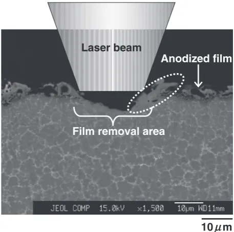
Figure 9 shows the cross-sectional observation result after the coating removal by laser irradiation. A coating was thoroughly removed. In addition, the substrate was also partially removed. In the broken line, the substance covering the anodized layer has been formed on the film edge.
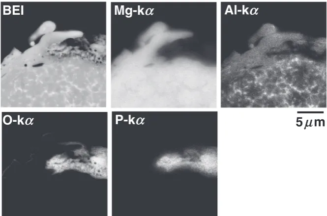
Figure 10 shows the backscattered electron image and X-ray maps with magnesium, aluminum, oxygen, and phos-phorus by FE-EPMA analysis in the broken line shown in Fig. 9. Anodic oxidation coating consisted of magnesium, aluminum, oxygen, and phosphorus. On the other hand, this substance covering the anodized layer shown in Fig. 9 only consisted of magnesium and aluminum without oxygen and phosphorus, and then magnesium and aluminum were uniformly distributed. However, on AZ91D magnesium alloy substrate, magnesium and aluminum were nonuniform-ly distributed because of the -phase composed of magne-sium element and -phase composed of an intermetallic compound of Mg17Al12. From these results, this substance
covering the anodized layer is proven to be different from the anodized layer which underwent fusion and solidification by laser irradiation. While the chemical composition of the overlying substance is close to that of the substrate, the microstructure (Fig. 9) does not show -phase. From this point, the overlying substance is considered to originate from the sputtered substrate or -Mg supersaturated by
100 2 10-2 10-6 10-4 Current density , i / A/m (a) (c) (d)
-1.8 -1.7 -1.6 -1.5 -1.4 -1.3 -1.2 10-8 (b)
Potential, E / V (vs. SCE)
Fig. 8 Anodic polarization curves of the various specimens. (a) AZ31B substrate. (b) Anodizing from the phosphate solution. (c) Laser irradiation (5 kHz). (d) Laser irradiation (50 kHz).
Laser beam
Film removal area
Anodized film
10
μ
m
[image:6.595.65.269.69.234.2] [image:6.595.312.541.71.298.2]aluminum due to rapid cooling. Consequently this sputter covering the anodic oxidation layer seems to bring about the conductivity.
4. Conclusions
The removal of anodic oxidation coatings on magnesium alloy from the phosphate electrolytic solution by the laser processing was tried in this study. The area where anodized coating was removed under the appropriate laser processing condition showed the excellent corrosion resistance as well as good conductivity.8)This improvement of the conductivity
is attributable to the removal of insulated anodized coatings. In addition, molten sputter formed from the magnesium alloy substrate by means of the laser thermo processing becomes covering the anodized layer, and this sputter then brings about the conductivity. On the other hand, excellent corrosion resistance is based on the sacrifice corrosion
protection by anodizing from the phosphate electrolytic solution. It seems that newly developed technology increases the application of magnesium products for electronic equip-ment.
REFERENCES
1) Y. Kojima: J. JILM58(2008) 526–548 (in Japanese).
2) M. Hino, K. Murakami, M. Hiramatsu, A. Saijo and T. Kanadani: J. JILM56(2006) 386–391 (in Japanese).
3) M. Hino, K. Murakami, M. Hiramatsu, A. Saijo and T. Kanadani: Mater. Sci. Forum539–543(2007) 1691–1695.
4) K. Murakami, M. Hino, M. Hiramatsu, A. Saijo, S. Kobayashi, K. Nakai and T. Kanadani: Mater. Trans.48(2007) 3101–3106.
5) M. Hino, K. Murakami, A. Saijo and T. Kanadani: J. Surface Finish. Soc. Jpn.58(2007) 767–773 (in Japanese).
6) http://www.yasuoka.co.jp/fhoton-beam-yvo4-laser-marker.html
7) The Dow Chemical Company, G.B.Pat.762,195(1956).
8) K. Nishomoto, Y. Mitooka, M. Hino and K. Murakami: Jpn. Patent Pending 2009-126698 (2009).
μμ
m
BEI
Mg-k
α
Al-k
α
[image:7.595.131.464.71.291.2]O-k
α
P-k
α
5