• No results found

Kiosk for 3D image acquisition of suspects

N/A
N/A
Protected

Academic year: 2020

Share "Kiosk for 3D image acquisition of suspects"

Copied!
6
0
0

Loading.... (view fulltext now)

Full text

(1)

Kiosk for 3D Image Acquisition Of Suspects

Shreyo Baksi - S1568124

Electrical Engineering, DM/DBM Group, University of Twente

[email protected]

Supervisor Dr. Ir. L.J.Spreeuwers

Abstract— This paper presents a proof of concept for an affordable setup to generate 3D face scans. The system is build using the Realsense SR300 and a curved slider system upon which the camera is mounted. An open source software from the intel Realsense SDK is used to generate scans from the hardware. The software is tuned to develop face scans in particular. The cloud compare software was used for viewing the 3D scans.

The scans are generated by tracking upto 78 landmarks on the face of the subject being scanned making it robust against slow movements while being scanned. The scanning is done at 60fps. The textures of the face are stitched by implementing a iterative closest point function. The eventual scan made, provides for a 3D point cloud with a coloured 2D texture masked on top of it.

The depth resolution is ideal between 20 to 25 cm from the scanner. The system is very consistent in generating high match-ing scores. The resolution per pixel is obtained at 0.6mm/pixel. The scans were visibly distinguishable. The scans can cover for 180 degrees of poses and the scans are well illuminated making the scans fit for multi-pose face scanning algorithms and can also be used to train classifiers of the same.

The above mentioned points are further discussed in detail and the decisions have been advocated for in the scope of this paper. Eventually The SR300 in this setup is capable of generating 3D scans for running 3D face recognition and Multipose face recognition algorithms.

I. INTRODUCTION

Over the years capturing mug shots has been the usual way to acquiring photographic records of suspects.These records are used to identify suspects from surveillance footage or images found online. Face recognition software are usually implemented to establish a match between the image of a suspect and pre-existing records.

Usually images recovered to run matches on have varia-tions in pose illumination and expressions as compared to the prerecorded images. This makes face recognition more challenging [8]. Certain researchers have also venture into 3D face reconstruction from pre-existing mug shots database [7]. This paper[7] concludes the lack of texture and depth information makes the problem more challenging. Article [8] also concludes that, 3D Face recognition approaches can handle pose variations much better than 2D techniques. 3D face recognition does seem to be the way to the future having broken the 99 percent barrier in face recognition[5]. The only road block is the fact that 3D scanning solutions are very expensive as compared to taking mug shots.

In contrast for day to day basis the law enforcement officials and the public still responds to images and sketches

of suspects. Mug shots are still placed on bulletin boards at police stations and other similar locations.

The idea is to build an 3D face acquisition system and establish a proof of concept that is cost effective and yet avails decent 3D image acquisition quality. The system will capture the structure and texture of the face of a suspect. Over the years 3D capture devices have become cheaper. For this project we look into the various cost effective 3D cameras and choose a camera from them. Secondly the suitable software needed to operate with the 3D cameras needs to be decided form the available options. The Key points for selection would be ease of setting up, usage,tuning parameters and the quality of the results generated. Produc-ing an acceptable 3D point cloud mesh and the skin texture of the scanned subjects face. The scans generated should viewed with relative ease, a software to cater to that requirement is looked into and selection is made. While making a kiosk there are multiple setups that can be possible.

In the scope of this paper we look into the various require-ments for the system and look into the possibilities to obtain the set requirements. Look into theories and other research available to aid the achievement of the set requirements. The out comes from the setup shall be tested for quality of scans generated,consistency of scans generated and ease of use while generating the scans. The results obtained are then analyzed and discussed. The analysis and discussion shall elaborate on the inferences made regarding the results. leading us to the conclusions and the scope for further development of the system.

II. REQUIREMENTS

In this section the qualitative and quantitative requirements expected from the system are enlisted in the form of bullet points. The quantitative requirements such as 3D resolution, image quality etc. The qualitative requirements such as smooth operation,ease of setup and modularity of the scans generated etc. Such attributes are enlisted below.

• Make 3D scans with precision 0.25mm of 3D accuracy.

• 2D colour captures of 720p quality with color accuracy and be decent exposure.

• 3D scans should have 2D textures appropriately stitched onto the point cloud with little to no visible traces of textures being stitched.

• A User interface to facilitate smooth operation and making scans from one window.

(2)

• The setup saves scans in a modular format to conduct post processing.

• Shall be robust and operate with consistency.

• The scans generated should be visibly identical to the subject being scanned.

• The setup shall be cost effective and reasonably cheaper

• The scans can be made as quickly as taking mug shots (approx 20 seconds)

III. POSSIBILITIES

There are multiple methods of making 3D scans readily available. in this section the various possibilities that could be incorporated to execute the aim of the project are discussed. 3D scanners are usually hand held like the artec eva [2] or stationary as a booth like the sharpify booth.

Sensing of depth is one of the fundamentals of 3D scanning. 2 widely used methods incorporated are the Time of flight and Structured light methods.

In a time of flight depth sensors, A set of signals are directed onto the object being scanned. The reflected versions of the signal are scanned or captured. The depth is calculated by multiplying the velocity of the signal and the time of flight yielding the depth of the surface. Although T.O.F sensors offers for better dynamic range in sensing depth it has a poor acquisition speed[3].

The alternative is structured light option is an alternative wherein patterns of light is put onto the 3D object being scanned and sensor captures its reflection of the structured light and decode it to generates a value for depth. This method is applicable for a limited range however in that range it is much faster than the time of flight setup.

In parallel to the technology of the sensors, the ergonomics of the person being scanned and ease of use are factors that have been looked into for developing this proof of concept. The probable setups either have the scanners in motion while, the subject being scanned is still or the other way around where the subject is in motion and the scanner is still. Alternatively another possibility is to have a multiple camera setup wherein multiple cameras can be used to scan the subject without having any movement.

The software used for implementing these possibilities also add variety. There are software development kits for most of the hardware such as the Realsense. SDK for the intel real-sense series of cameras. Some of them are free access whilst some require the users to apply for a license.

In the scope of this project we have made choices among the above mentioned possibilities to develop a working proof of concept.

IV. THEORY ANDRELATEDRESEARCH

In this section we discuss the reason for the choices that were made in order to build the proof of concept. Also elaborate on how certain processes have been executed to achieve the scans and the results.

A. Camera

The different methods for capturing depth could be short listed to 2 major types namely structured light and time of flight. Structured light as the name suggests, a pattern of light is projected upon the subject being scanned. The sensor capturing the pattern projected reads it in a combination of individual bits describing the depth of the object. An alternative is to have a time of flight cameras wherein pulses are directed towards the subject and the reflections are captured and the depth on surface being measured is defined. The Time of Flight cameras have provided for some very high detail scans of objects however they can take long duration to make scans. TOF scanners tend to be very expensive at thousands of euros. As an alternative structured light systems are accessible at way more affordable prices.

[image:2.612.320.560.351.429.2]

Having established a preference for affordable structured light scanners we probe into the 3D cameras available off the shelf. The Intel real sense range and the Kinect from Microsoft were some camera ranges that suited our require-ments. The Software development kit(SDK) from Real-sense is more up-to date and easy to access as compared to the Kinect from microsoft SDK. Thus we choose to look into Intel Realsense range of cameras.

Fig. 1. The contents of the camera module of SR300 [4]

The Intel real-sense SR300, D430 were some of the 3D capture cameras available. The SR300 was chosen as it has 640x480 monochromatic infrared sensor for sens-ing depth enablsens-ing it to measure up-to a 3D resolution of 0.125mm/pixel. A Class 1 laser compliant coded light infrared projector system projects structured light. The color sensor is a 1280x720 chromatic sensor with discrete I.S.P. These features although not at the cutting edge of technology they do avail for acceptable results with that 3D resolution and the SR300 costs almost a third the price of the D435. Alongside that the real-sense Software Development kit was more complete in the applications that it avails us. These factors advocated the choice of the SR300 over the newer D435 or some of the other options. The figure1 illustrates the internals of a SR300 camera module. The figure 2 tabulates the components from figure1 and their respective description [4].

B. Software

(3)
[image:3.612.334.537.51.218.2]

Fig. 2. A table of the contents of the SR300 module chosen [4]

body and object are availed to the user, in this case the face option is selected. The application offers options of capturing the following featuresLandmarks,Solid,Textures and Marker. The color camera is set to a resolution of 1280x720 and a depth sensor of 640x480. The software is operated with scanning of Landmarks and Textures as these give us a 3D structure of a face and a color texture masked on top of it. Once the scan has been made it can be transformed and saved as a (.obj ,.pyl or .stl) files. This software gave consistent results and yields scans in our desired formats. Figure 3 illustrates the user interface.

Fig. 3. Screen Grab of the scan3D.cs software

C. Landmarks

The landmarks are points that are extracted from a 2D image of a face. In this case the landmarks are scanned and paired with their respective 3D entities. The landmarks are traced to analyze the motion and make captures by the software. The landmarks are used to track the face while scanning the face.This makes the system robust against any slow movements by the subject being scanned. The system is able to track with up to 78 landmark points on the face. The landmarks are illustrated in the figure 4.

D. Texture

[image:3.612.67.288.54.152.2]

The texture is captured as a set of images of the subject’s face. These images required to be stitched upon the 3D point cloud of the subject scanned. The software is tuned such

Fig. 4. landmarks on the face of the subject being scanned

that the adjacent patches of images are joined smoothly on the surface of the object whilst sustaining the continuity of color and picture. There are 4 major sub-phases (vertex-to-image, patch growing,patch boundary smoothing,texture-patches packing)to the process of stitching process [9].

Vertex-to-image bindingIn this step the most orthogonal image with respect to the a given vertex on the scan is chosen.

Patch growing Herein the vertex to image relation is iterativly refined. The iterations are such that any 3 set of points(vertices of each triangular face)are linked to a respective patch on the image and also its adjacent images and form frontier faces.

Patch boundary smoothingThe frontier faces that were created in the previous step may have discontinuities and the are smoothed out in this step.The discontinuities are smoothed out by re-sampling the frontier faces and com-puting a weighted composition of every targeted triangular section in the associated target images.

Texture-patches packing All the previously computed information are mapped to a rectangular texture map and a texture coordinates in the triangle mesh . They are updated respectively as the operations are run.

[image:3.612.53.308.338.521.2] [image:3.612.331.537.552.698.2]
(4)

E. Process

[image:4.612.74.278.242.460.2]

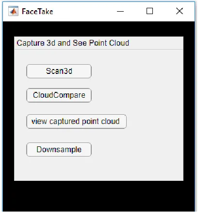
The process of capturing the 3D scan is to use the C# based programScan3D.cs.The software saves data as a .obj file. Saving in a .obj file allows us to access the data as a point cloud as well as a individual textures depending on the purpose of post processing. The above mentioned data can be accessed. The Cloud-compare.V.2.6.3 is utilized to visualize the captured 3D data and the texture placed onto it. The above mentioned software are free to access advocating the choice of using them over other options. Alongside it a mat-lab application is developed to click open each individual software separately from one entity. A screen-shot of the MATLAB app is shown in figure6. This provided for a convenient way to run the processes from a single window.

Fig. 6. A MATLAB app to run all the different elements of the process from a single window

V. SETUP

There many 3 significant possibilities to setup the scanner, In the scope of this project 2 of the setup were built. Setup 1 has a still camera and the suspect is moving while setup 2 has a mobile camera while the subject is still while setup 3 has multiple cameras and both cameras and suspects are still while capturing takes place.

For setup 1 a camera is placed on top of a stationary tripod mount, the subject being scanned is expected to move their head left to right by 20 degrees on either sides while their face is being scanned.

For setup 2 a curved slider setup is used , The camera is mounted on a slider mounted on a curved rail. The rail is arcing around a rail for 90 degrees.The suspect is expected to sit still while the scanner moves along the rail as it is scanning.This setup is illustrated in figure10.

For setup 3 we looked into having a multiple camera setup. where in the subject and the scanner both will need to be

stationary for the duration of the scan however the duration shall be much lesser than the other 2 setups.

Setup 3 required for multiple cameras and that makes it the costliest setup to build as it required for double the number of cameras. Setup 2 with a camera and a slider provides for stable and consistent scans as the subject is expected to be still while the camera moves along a fixed path.However the sliding mechanism adds a bit of usability and robustness its more expensive to setup as compared to setup 1. Setup 1 is the most economically viable among all the possible setups. It can be built upon a standard tripod stand connected to a laptop. A negative for setup 1 would be high amount of inconsistencies in the scans made as its depended on the suspects movement that may not be ideal all the time. In the scope of this paper most of the tests were run on scans made on setup 2 the curved slider setup as it made for a smoother and robust scanning setup.

VI. TESTS

A. Test 1

For this test the 3 scans are made at at distance of 20cm 25cm and 30cm from the sensor and the elements. We look into the similarities and differences visible in the respective 3D scans and comment on the performance. The prime objective is to visually verify if the pose and the illumination are captured properly, The scans were also matched against one another to identify how similar or indifferent each scan is to one another.

B. Test 2

The Fixed far vote Fusion test is developed by Luuk Spreeuwers. It has a registration and integration algorithm and has been use in his recent papers, FFVF(Fixed Far Vote Fusion) [5][6]. FFVF accepts multiple 3D point clouds of faces as an input and calculates a certain matching score among the various 3D scans. In this test the images are divided into multiple regions using masks. Each mask uses PCA(Principle Component Analysis) and LDA(Linear Discriminant Analysis) classifiers to compare a section of the face from a scan to the same section of the face captured in another scan. A score between 0-60 is allocated between a pair of faces scans by a process of majority voting over all regions. The scans of the same face should return higher scores while the scans of different faces should return low scores. The algorithm for this test yields 99.3% verification rate. This test is used to verify the consistency, integrity and the quality of the setup.

C. Test 3

(5)

VII. RESULTS

A. Results for test 1

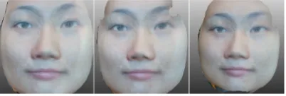
The results have been illustrated in the figure 7.It has 3 images of the scans taken at 3 different distances from the scanner and the matching scores are tabulated. The scans are found to be visibly similar to that of the subject scanned.The matching scores mentioned in table I agrees to the same.

Scan Details

Matching scores

Scan at 20cm

60

58

58

Scan at 25cm

57

60

55

Scan at 30cm

59

57

60

TABLE I

[image:5.612.74.278.162.251.2]

MATCHING SCORES YIELDED FROM COMPARING THE3SCANS AGAINST ONE ANOTHER

Fig. 7. A figure showing the scans taken at distances of 20 25 and 30 cm from the scanner

The results from this test also certifies proper illumination for each of the scan as all parts of the face are evenly and smoothly illuminated and no shadows show up on the scans. Scans can appear different under different kinds of light and proper illumination makes for the skin to have a consistent tone and texture.

B. Results Test 2

The results tabulated in table II and I show the matching scores of scans of the same person the scans were taken at different instances and still yield high matching scores. This result advocates that the system is consistent in making scans useful to run 3D face recognition algorithms upon.

C. Results test 3

The figure 8 illustrates how the FFVF software visualizes and analyses the scans. The left most image is taken by a professional setup while the 2 samples on the right were taken by the setup built. The resolution for these captures is at 0.57mm/pixel and 0.66mm/pixel.

VIII. DISCUSSION

The objective of this project was to develop a proof of concept for a system that is capable of making 3D scans with a low budget and a using off the shelf components and deliver scans that can be used for face matching algorithms and generate consistent results. From the established results

s1

s2

s3

s4

s1

60

58

58

59

s2

57

60

55

58

s3

59

57

60

59

s4

59

57

58

60

TABLE II

[image:5.612.77.278.312.380.2]

THE TABLE OF MATCHING SCORES FOR TEST2,COMPARING4SCANS OF THE SAME SUBJECT AGAINST ONE ANOTHER

Fig. 8. Scans as evaluated and visualized by FFVF software

it is seen that the system is capable of producing consistent scans. Test 1 it can be inferred that the illumination and pose of the scans are consistent. These scans can be used to run face matching algorithms as well as it can be used to generate images of faces with multiple poses as compared to the 3 poses that were provided by classical mugshots. The ring lighting in the setup produces a shadow free image on top of the scan.This makes the scan well illuminated. Pose and illumination have been a challenging issue in face recognition algorithms [8]. On the basis of these results this setup can be capable to train face recognition classifiers.

The results from test 2 establish the fact that this system is capable of making consistent face scans. The matching scores are high for the same faces being scanned. However the scans are consistent only in a specific range of distance from the scanner. The detail of depth in the scans are lost over the distance of 25cm from the scanner.

(6)

pro.xyz

gl1a.xyz

gl1b.xyz

pro.xyz

60

9

9

gl1a.xyz

7

60

57

gl1b.xyz

7

57

60

TABLE III

[image:6.612.53.308.58.146.2]

TABLE OF MATCHING SCORES COMPARING3SCANS

Fig. 9. Images taken from the scan showing multiple poses that could be acquired from the 3D scan

respect to scans made by another system are significantly lower. This could be attributed to the lack of Depth detail and can be enhanced by placing the scanner as close to the subject being scanned as possible. Another way around this problem would be to have a higher resolution depth sensor. Apart from the tests the system is convenient to set up in a windows and Linux OS based PC, The software’s used are all open source software’s that do not require purchasing a license and over time they have been performing smoothly and are easy to setup and use. However to obtain good scans the subject is expected to be closer than 25 cm from the camera. On the positive side the final output of such scans can be utilized to view a image from multiple poses and have equivalent illumination on most parts of the face. Thus making these scans useful in training classifiers for multi-pose face recognition systems.

Fig. 10. The setup with curved slider

IX. CONCLUSION ANDIMPROVEMENTS

The objective of this project was to develop an affordable 3D Face scanning system which can make decent 3D scans that could be used as an alternative to the classical mug shots in Scanning the faces of suspects. The conclusions that were reached upon were as follows. The scans developed were able to capture 3D depth and images scans using a structured light camera in combination with a RGB camera. The scans if made at 20-25 cm from the cameras and under decent ambient lighting make for decent 3D scans with 3D resolution of 0.6mm/pixel and image resolution of 1280x720 pixels in 2D. The proof of concept developed was made with equipment costing less than 200 euros. The system yields consistent scans which provide for high matching scores when tested with a face recognition software. An image of the setup is illustrated in figure 10

Some drawbacks that also provide us with scope for improvement are as follows. The limited depth resolution camera is a drawback this can be fixed by using a camera from the Intel Real-sense 400 series and complementary software along with it.

Some alternative uses for the scans developed by the system would be train classifiers for multiple pose face recognition systems since the scans are void pose and il-lumination based discrepancies.

There is a lot of scope for further development in refining the user interface for the system . One alternative way to make scan is by utilizing a robotic arm instead of a curved slider setup since the distance from the scanner causes significant differences in results. The system could be better tuned for the needs of multi-pose face recognition based on the requirements of specific algorithms.

In the scope of this project we were able to develop a system to acquire 3D scans for the fraction of the price of professional 3D scanners. The scans generated are consistent and modular. However there is lot of scope for further refine-ment with better depth sensor and better written software.

REFERENCES

[1] G. O. Young, Synthetic structure of industrial plastics (Book style with paper title and editor), in Plastics, 2nd ed. vol. 3, J. Peters, Ed. New York: McGraw-Hill, 1964, pp. 1564.

[2] Portable 3D Scanners. Handheld 3D Scanners — Artec 3D — Portable 3D Scanning Solutions, www.artec3d.com/portable-3d-scanners. [3]

https://www.spar3d.com/news/related-new-technologies/time-of-flight-vs-phase-based-laser-scanners-right-tool-for-the-job/

[4] 82535IVCHVM Intel — Mouser. Mouser Electronics, eu.mouser.com/ProductDetail/Intel/82535IVCHVM?qs=

[5] Luuk Spreeuwers. Fast and Accurate 3D Face Recognition. In: Inter-national Journal of Computer Vision 93.3 (2011), pp. 389414. ISSN: 1573-1405. URL: http://dx. doi.org/10.1007/s11263-011-0426-2. [6] Luuk Spreeuwers. Breaking the 99of 3D face recognition. In: IET

biometrics 4.3 (2015), pp. 169178. URL: http://doc.utwente.nl/95850/. [7] Zeng, Dan, et al. Examplar Coherent 3D Face Reconstruction from Forensic Mugshot Database. Image and Vision Computing, vol. 58, 2017, pp. 193203., doi:10.1016/j.imavis.2016.03.001.

[8] Jiang, Dalong, et al. Efficient 3D Reconstruction for Face Recog-nition. Pattern Recognition, vol. 38, no. 6, 2005, pp. 787798., doi:10.1016/j.patcog.2004.11.004.

[image:6.612.56.306.185.263.2] [image:6.612.54.314.514.707.2]

Figure

Fig. 1.The contents of the camera module of SR300 [4]
Fig. 2.A table of the contents of the SR300 module chosen [4]
Fig. 6.A MATLAB app to run all the different elements of the processfrom a single window
Fig. 8.Scans as evaluated and visualized by FFVF software
+2

References

Related documents

Today, high-throughput X-ray crystallography, advanced computational tools, and parallel organic synthesis have been combined to meet these challenges and provide new

K AN. The general thinking is that hostile work environ- ment cases are disparate treatment cases, but not all commentators agree that all hostile work environment cases have to

The objectives of our study were: (1) to quantify alpha and gamma diversity of understory vascular plants, bryophytes and lichens in pure and mixed stands by investigating tree

Afghanistan, Egypt, Angola, Bosnia-Herzegovina, China, Germany, Hong Kong, Iraq, Iran, Iceland, Italy, Kingdom of Saudi Arabia, Korea, Croatia, Lebanon, Libya, Macau, Malaysia,

Oyster mushroom (Pleurotus ostreatus)is known for the presence of numerous nutritional compositions and various active ingredients, and it have been reported to have antidiabetic,

In this paper we investigate the Sum Absolute Difference (SAD) operation, an operation frequently used by a number of algorithms for digital motion estimation.. For such op- eration,

The relevant costs are direct material cost, direct labour cost, direct expenses, variable production overhead, opportunity cost, and incremental fixed cost..

Thus, on the one hand we see that brokerage institution Laluz overcomes barriers which are related to volunteerability (people involved themselves in